


1. Introduction
The consequence of our deep reliance on fossil fuels is becoming more severe every year. The combustion of fossil fuels has been concretely linked to climate change which according to the WHO causes an additional 250,000 deaths every year [1]. That is just one of the many consequences of our dependence on fossil fuels. A major use of fossil fuels is in transportation mainly automobiles resulting in the transportation industry emissions reaching 25% in 2019 [2]. Due to this, scientists have been making efforts to optimize internal combustion engines (ICE) including energy recovering techniques as well as producing different modes of propulsion systems such as electric vehicles all in an attempt to reduce fossil fuels usage. This paper offers a review of different energy recovery techniques and how they can be implemented in automobiles. Energy recovery techniques harvest energy wasted by the vehicle during processes such as braking and heat lost to the surroundings. This not only reduces the consumption of fossil fuels diminishing the impact upon the environment but improves fuel economy allowing for the car to be cheaper to run and to have a larger range.
They are numerous energy recovery system (ERS), which can largely be broken down to kinetic and thermal. Kinetic ERS deals with moving objects that’s energy that would typically be transferred to the surroundings, moving exhaust gasses, spinning wheels and axles that grind to a halt during braking. Thermal ERS deal with converting heat that too would be transferred to the surroundings primarily engine blocks. Rankine systems and thermoelectric systems are an example of thermal ERS. These recovery systems have great potential in hybrid cars, however with the UK plans to ban the sale of new hybrid cars by 2035. There is a global push in the automotive industry to make the switch to EVs, reducing the effectiveness of these systems [3], Royale and Simic was able to predict that a thermoelectric generator in a Porche 918 under some circumstances could produce a continuous 200kW of electricity, which is 31% of the hybrids power output [4]. However, an organic Rankine cycle can still be used as a temperature control for an EV battery with Sim et al finding that their proposed system had a heat recovery rate of 77.78% producing an overall output of 98W. This is enough power to charge a laptop [5]. Further research in Thermal ERS should be pursued as they can still be used as cooling systems which are carbon negative and help reduce fuel consumption, but Kinetic ERS still have a greater effect on fuel consumption and are largely applicable in any propulsion system.
The ERS this paper will focus upon are: Regenerative braking, Mechanical flywheels and Regenerative electrically assisted turbocharger (REAT). Each of these methods will be compared using the three criteria of energy recovery, applications and system configuration – including space, weight, cost, etc. As literature largely focuses on improving the efficiencies of ERS systems placing them underneath specific driving styles and conditions a general theoretical optimum value of energy recovery has not yet been determined for ERS systems [6]. However, researchers have still been able to find energy recovery underneath certain parameters. For example, Xu et al. used both simulations and experimental validation found that by optimizing influencing factors for a regenerative braking system of a hybrid the energy recovered could reach as high as 83% [6]. These results can be used as an estimation for ERS high potential to improve recover wasted energy. In terms of application it is important to consider how readily the technology can be implemented in current vehicles. Lee et al. investigated the performance between REATs and traditional turbochargers over several requirements including topologies, steady-state performance, and control techniques on various types of high performance engines. They found REATs were a valid turbocharger. The last criteria is system configuration this focuses not only on the components of these systems but the weight, cost and size of these parts. Hemsen et al. by analyzing production methods was able to develop a cost model determining the cost of a Permanent magnet synchronous machine (PMSM) to cost between 353 and 700 Euros. This is insignificant investment compared to the prediction that an Opel Corsa will cost 352,974 euros over its lifetime [7]. These cost models allow for a rough estimation of the cost of the ERS and where to reduce manufacturing costs.
This paper will investigate three ERS over energy recovery, applications and system configuration – including space, weight, cost, etc. Their performance in the three criteria will give an insight into their potential and where further research should be carried out.
Research Question. Is there an energy recovery system that is ready to be implemented in commuter automobiles to increase their fuel economy.
Research Hypothesis. A comparison of three energy recovery methods based on total energy recovery, system configuration, and application feasibility will identify regenerative braking as best for new vehicles to decrease fuel consumption and electrically assisted turbocharges as best for retrofitting older vehicles.
2. Discussion
2.1. Mechanical Flywheels
A mechanical flywheel is a kinetic energy storage device [8]. As shown in Fig.1, it has a peak efficiency at over 90 precent making it very good at storing kinetic energy. It also has a relatively consistent rate of efficiency [9]. A new application of the flywheel are in commuter vehicles acting as a form of regenerative braking. They are a very efficient form of regenerative braking as instead of transferring kinetic energy to electrical energy they keep it as kinetic energy reducing energy lost during transmission. When the brakes of an ICE car are engaged, the kinetic energy is redirected from the wheels to the flywheel. As seen in Fig.4 this is done by a clutch from the flywheel engaging to the drive train this in turns spins the flywheel the clutch then disengages when the axle is stationary and reengages so that the stored kinetic energy can then be used for acceleration. This allows an ICE engine to have regenerative braking without requiring heavy and expensive batteries and generators. This can also be applied for hybrids and EVs in which the kinetic energy of a flywheel is transferred to electrical energy via a generator which can be used to charge the cars batteries whilst also aiding in acceleration [9].
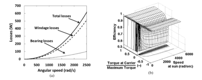
Figure 1. Maps of (a) losses at the flywheel and (b) efficiency of the flywheel [8].
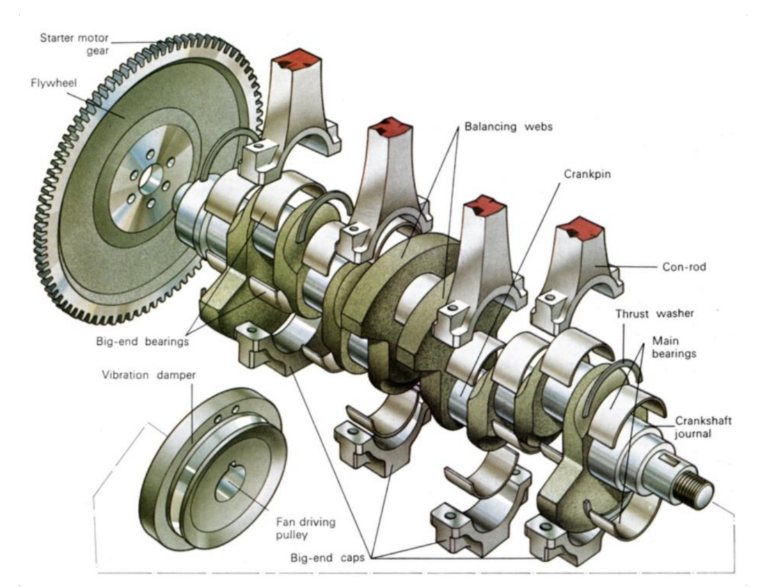
Figure 2. Schematic of flywheel [10].
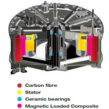
Figure 3. Composite flywheel developed by Williams F1 [11].
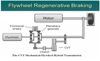
Figure 4. Flywheel gear system [12].
Mechanical flywheels have a high initial cost relative to fuel saved. This can be due to its low energy density which can be increased by utilizing lightweight materials. This makes the Mechanical flywheel lighter and therefore it is able to store more energy per kilogram allowing it to not only take up less space in the vehicle but also reduce the vehicle fuel consumption. To find the suited material the design must be first chosen between a low speed mechanical flywheel energy system (LSFESS) or a high speed mechanical flywheel energy system (HSFESS). Automobiles regularly use LSFESS as they operate underneath 10,000 rpms but can still rise to up to 30,000rpm. A simulation of a low LSFESS was created and different materials were tested such as composites and steels to see which would be the most optimal.
For vehicle applications, a flywheel made of High strength steel is best. A high strength steel flywheel’s energy density is 100-200 kJ/kg compared to ceramics which has 200-2000 kJ/kg and composite: CFRP has a 200-500 kJ/kg its energy density is average [10]. The more energy dense the material selected the lighter flywheel and therefore the less energy required to transport it. Ceramics and composites are more energy dense but are more expensive than high strength steel. Virgin CFRP costs 28 dollars a kg [13] whilst high strength steel costs 2.2 dollars [10]. High strength steel being an industry norm is easier to machine and not as prone to failure as ceramics or composites [10]. This leads to a Volvo S60 Sedan equipped with an FESS system gaining a 25 percent reduction in fuel consumption. This presents the FESS as an effective system, That is desirable to implement and of interest to be further improved as designs are optimized and materials become cheaper and more available.
Table 1. Energy densities of different materials when used for FESS [10]
Material | kj/kg | Comments |
Ceramics | 200-2000 | High failure rates so rarely used Most popular, used in a wide range of applications Also widely used, Less range than CFRP but cheaper High costs and challenging to work with These blends are all equal in strength and applications. Steel and aluminium are less expensive than magnesium and titanium Traditionally used when requiring high density and in low-speed applications |
Composites:CFRP | 200-500 | |
Composites: GFRP | 300 | |
Beryllium | 100-200 | |
High-Strength Steel | 100-200 | |
High-Strength Al Alloys | 100-200 | |
High-Strength Mg Alloys | 100-200 | |
Ti Alloys | 100-200 | |
Lead Alloys | 3 | |
Cast Alloys | 8-10 |
A mechanical flywheel can be broken down into 4 main components: the flywheel, the flywheel housing, the generator, the gear system. For other applications maximizing energy return is most sought after however for a commercial vehicle there is a common consensus that power density and cost is most important. The most optimal system configuration is to implement the lightest and cheapest components available. The system should then be designed to be as compact as possible due to the limited space of an automobile. As each vehicle have different requirements that designers have to refill, the information above are simply guidelines.
This is a brief list of the machines used in mechanical flywheels.
• Permanent magnet synchronous machine (PMSM). Derived from a holistic look of manufacturing they have a cost between 353-770 euros [14]. PMSM also have a high efficiency which makes them very popular in EVs.
• Induction machine. From a manufacturing perspective they cost roughly between 50-500 pounds for motors to be used in EVs. [15] It is very efficient but not to the same standard as a PMSM. As can be seen in Fig.6 the efficiency of the machine increases as it has a higher rating. The machine is also reliable [16].
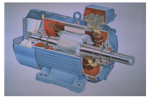
Figure 5. View of a modern squirrel cage in an AC induction motor. The picture presents the stator and rotor construction, cooling fan and a shaft with bearings [16].
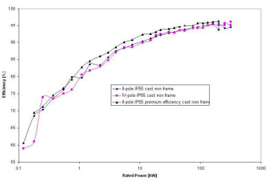
Figure 6. Rated load efficiency of IP55 cast iron frame induction motors for a 2 and a 4 pole standard efficiency motor [16].
• Homopolar DC generators. It produces DC current so it doesn’t require an inverter. It is simple and quite robust and achieves a high torque at low speed so it can be readily applied in the automotive industry. It has very small contact resistance as seen in fig.8 making it very efficient [17]. It produces a high current but low voltage so it can only support low voltage car systems without changing its voltage. There was no data available to me to find the average cost of a homopolar generator [17].
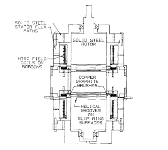
Figure 7. Homopolar DC motor [17].
Flywheel housing can be further broken down into bearings and containment. The bearings available for mechanical flywheels are magnetic bearings. Magnetic bearings can accommodate high rotational speeds making mechanical flywheels viable. They don’t require lubrication and have very little maintenance requirements. The several magnetic bearings implemented are listed below.
• Permanent magnetic bearings (PMBs) utilize permanent magnets as seen in Fig.7 this gives them a higher magnetic flux density than electromagnets, have a low cost and don’t suffer from electromagnetic drag. It does make them unable to dampen movement from all directions so they are typically used as auxiliary bearings due to their affordability [10], [18].
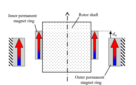
Figure 8. permanent radial bearing[19].
• Active magnet bearings accommodates electromagnets that can respond to the forces exerted on the motor by changing their own electromagnetic force. This is accomplished by a feedback system monitoring the stability of the shaft. This causes the electromagnet to vary their magnetic field strength keeping the shaft in balance [10].
• Superconducting magnetic bearings are suitable for very high speed application and provide a near friction free bearing. However, one of the highest critical temperatures recorded for a superconductor is 166 K at 23 GPa [20]. This temperature is impractical for a vehicular application and will not be further considered.
Flywheel containment should be a vacuum as the sheer angular velocities would be impossible to efficiently maintain. This means that there must be regular checks to ensure that the vacuum seal is still in check and that the flywheel is underneath optimal temperature to prevent warping [21]. Theoretically the mechanical flywheel should have infinite cycles but as there is still some friction it will wear away components and regular checks are still necessary but not as often as other ERS [21].
Flywheel design must be further researched for the specific application according to what material has been selected and physical constraints. The gear system can be created bespoke for each vehicle. However, it should have a top speed of 30,000-50000rpm and a minimum of roughly 7500-12500prm [21]. This 4:1 range will allow the flywheel to be able to conserve 94% of the kinetic energy [21].
This technology is readily applicable to most new commercial vehicles, as it stores kinetic energy it can be used in ICE cars without the addition of a motor. This means the designer must have enough space in the powertrain to facilitate the mechanical flywheel. This makes it very difficult to retrofit existing cars as the expense to implement it would negate any financial benefit. A specific patented flywheel called the AFS flywheel cost several thousand pounds. The average cost of petrol in the UK during the writing of this article is 145.1p per liter. This article states that if a specific mechanical flywheel system costs an estimate 2000 pounds and increases a car’s fuel economy by 25% as found by Diego et al [8],[21]. it will take 5674 liters before the system paid for itself. In 2008 the average consumption of petrol per capita was 4420 liters [22]. That means it will take 2 years for the system to have a financial benefit.
Regenerative braking can reach up to 50%. I believe that further investigation of mechanical flywheels with regenerative braking can provide one of the key pathway to improving that figure.
2.2. Regenerative braking
Regenerative braking can work on any vehicle, it works by the principle by converting the kinetic energy of the car into a battery [23]. As demonstrated in fig.10 when the drivers wants to break the energy flows from the wheels to an electric motor, which acts as a generator generating electricity which is then stored in a battery [23]. Regenerative braking does slow the car down but it cannot completely replace friction brakes so they still must act in combination with retarted friction brakes.
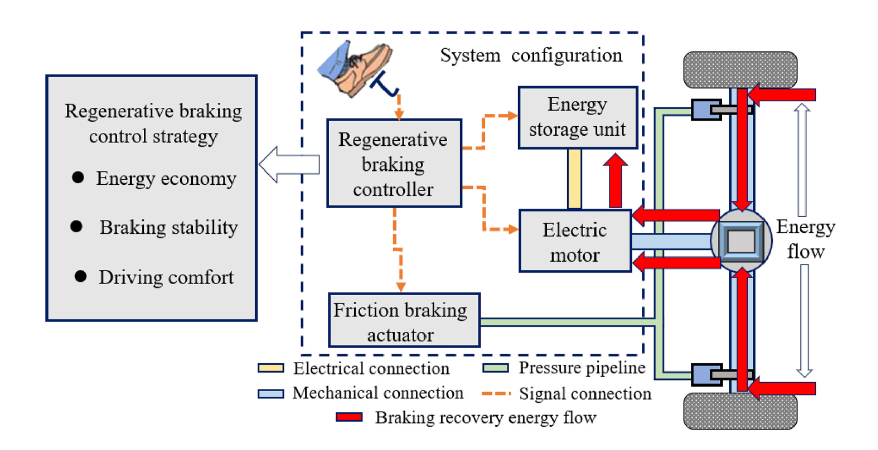
Figure 9. Logic framework of regenerative braking for EVs [24].
Regenerative braking has numerous forms of collecting energy from brakes by using hydraulics, an elastomer unit, mechanical flywheels and more. They all use the same principle of harvesting kinetic energy from the vehicle braking and using that to turn a generator. Therefore, instead of investigating the different forms of regenerative braking it is best to look at control strategies as they maximize the energy recovery [25].
By selecting the most optimal regenerative braking strategy it allows for the regenerative braking system to be active for a longer duration during braking. This increases the ERS energy recovery. Yang et al. carried out a simulation of regenerative braking using four different strategies: a coordinate regenerative efficiency with brake pedal feel, controlling the opening of inlet valves of the front axle to regulate wheel cylinder pressure, create a predefined gap between a brake pedal and a brake booster by introducing a linear solenoid actuator and add two modulating valves in conventional pneumatic brake lines [24]. These four different strategies were used for a parallel regenerative braking system in which friction braking force and regenerative braking force keep a constant proportion. A serial regenerative braking strategy which has independent control of friction braking and regenerative braking allowing the regenerative braking to have priority and simple use friction braking to make up the difference. Front and rear axle braking force distribution (BFD) strategy is in which the braking intensity is varied due to how demanding of braking the car requires. Single-pedal braking control strategy is responsible to the pressing of the brake pedal changing between the strategies mentioned above so it has both single pedal mode which is for more than 90 precents of scenarios and reserved brake pedal for emergency braking. This has been installed in Tesla’s which give them a higher energy recovery potential [24].
Of the 3 strategies mentioned the Front and rear axle BFD strategy proves most promising as it harvests energy in both axles. However for front or rear drive cars they typically use mild braking this most greatly suits a parallel Regenerative braking strategy as it is relatively simple and can be easily implemented into cars. Furthermore its shortcomings in being able to vary the regenerative braking can be solves with the strategies mentioned earlier. Creating a predefined gab between a brake pedal and a brake booster by introducing a linear solenoid actuator allows the regenerative braking to be triggered first and if an emergency brake is required that utilized friction braking is necessary that can then be used by pressing even further on the brake pedal. This increases the efficiency of this system by 38 precent giving a greater return in energy [24].
Regenerative braking use the same generator as a mechanical flywheel so the main components to look at now are their control systems which this paper has already given an insight upon friction braking actuator which is similar to that of a conventional braking system and batteries. Given that batteries are an incredibly important technology not only for energy recovery but also for electric vehicles they has been constant development in numerous areas including solid state batteries, potassium ion batteries, organic batteries. The best battery must be chosen that not only prevents the loss of any energy but also is sustainable and can easily be decommissioned. In terms of battery energy storage Dehghani-Sanij et al. investigated Pb-A, Lithium ion, Na-S, Ni-CD, Vanadium redox and Zn-Br lifetime. They found their cycling times and cycle efficiency was by charging them to 100% and leaving then draining them repeating that process until the battery could no longer function. Energy density and power density was investigated by charging the battery and seeing how much charge it can hold [25].
In terms of life cycle Ni-Cd batteries had the longest lifetime lasting from around 10-20 years compared to other batteries which largely had a life cycle of 5-10 years including lithium ion batteries [25]. The one with the longest cycles was Vanadium redox with 12000+ however Ni-Cd still had between 2000-2500 and Lithium ion had between 1000-10000. Ni-Cd had the lowest efficiency of 50-70 precent whilst Lithium ion had 90-97 precent with Vanadium redox between 75-85 precent. Lithium ion also has the highest energy density of 200-500 Wh/L out of the three and the highest power density of 1500-10000 W/L. In terms of battery choice without looking at the economics Lithium ion seems the best choice as although it has the shortest battery life cycle it has the highest efficiency meaning most of the regenerated energy is kept and has the highest energy and power density. In terms of cost for power Lithium ion costs 1200-4000 dollars per kilowatt compared to 500-1500 for Ni-Cd and 600-1500 for Vanadium redox. In terms of Energy Capital cost Ki-ion has 600-2500 kJ compared to 800-1500 for Ni-XD and 150-1000 for Vanadium redox. Lithium ion however has no operating and maintenance cost as well as the fact that it is very accessible and is now an industry standard. Even though Lithium ion is incredibly polluting compared to other choices it is still the best choice at the moment but as other battery technologies are introduced their efficiency will rise and costs will decrease [26].
2.3. Regenerative electrically Assisted Turbocharger
A turbocharger is a type of gas turbine. A gas turbine converts high temperature and high pressure gas into electric energy [27]. This gas comes from the exhaust gas from the car’s combustion engines [28]. The turbocharger is spun by these exhaust gas this then turns a compressor which forces fresh air into the engine. Regenerative electrically assisted turbocharger (REAT) has a motor/generator connected to the turbocharger. When the engine needs to burn a lot more fuel immediately there is a lag before the turbocharger is able to provide enough air for efficient combustion. The motor can spin the turbine reducing the turbo-lag. This increases the engines efficiency, saving fuel and increasing engine performance/handling. However when the engine does not require as much air the motor acts as a generator which the turbine spinning, producing electric energy that charges a battery. The energy recovered can spin the motor. A REAT usually has a net positive of power, reducing fuel consumption of the car and increasing the economy of the car.
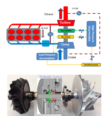
Figure 10. System layout of diesel engine with hydraulic assisted and regenerative turbocharger, along with an integrated system in subcenter housing [29].
There are two systems for assisted turbochargers. The hydraulic assisted turbocharger is a compact design and can be directly integrated into the turbocharger housing. The hydraulic pump is mounted on the TC shaft and just like an electrically assisted turbocharger recovers energy from the exhaust gas. Due to the pressurized fluid of the hydraulic assisted turbocharger it can be utilized to directly drive the turbine. This sudden acceleration leads to an improved turbine efficiency. This is different compared to an electrically assisted turbocharger which instead uses an electric motor which requires a power output of between 0.2-10 kilowatts to meet the acceleration of the hydraulically assisted turbocharger. This is tested by creating a simulation of both hydraulic assisted turbocharger and electrically assisted turbocharger. The simulation is based upon a 10,000 pound vehicle with a baste transmission shift strategy, boost pressure set-point, fuel injection point and an EGR fraction set point to substitute for the base engine [28].
Although this hydraulic assisted turbocharger is a novel approach and has many advantages it only leads to a 4% fuel economy improvement compared to that of a 6% fuel improvement of an electrically assisted turbocharger. This largely due to large technical issues of the hydraulic power input that is required compared to that of an electrically assisted turbocharger. This means that an electrically assisted turbocharger is far more preferable to a hydraulic turbocharger and any further discussion is moot until those technical issues have been solved [28].
A specific system configuration cannot be chosen for an electrically assisted turbocharger. This is because a turbocharger is largely designed for the engine. The purpose of an electrically assisted turbocharger is to provide a fast boost response, improve fuel economy and have minimal impact upon the engines emissions. Therefore, in terms of changing system configuration it is unnecessary given that this article has a detailed discussion of machines and batteries. An induction machine could be a viable option as it would the necessary torque and has a high efficiency rate. [30].
3. Conclusion
In conclusion, this paper analyzed three different ERS and compared them using three criteria. Mechanical flywheels has a high energy efficiency as it does not transfer the collected kinetic energy to useful electric potential energy. Electrically assisted turbochargers can be easily incorporated into new or retrofitted into old ICE cars for immediate energy recovery. However, ICE cars are starting to be phased out and replaced with EVs, which means that implementation must begin immediately so that it can have as significant an effect as possible. Regenerative braking has a very high amount of energy recovered and can incorporate mechanical flywheels as a battery. Therefore, information in this article is used to conclude that regenerative braking has the highest return of energy and should be implemented as soon as possible with further research focusing on how best to improve their efficency.
References
[1]. “Climate change.” Accessed: Jul. 20, 2024. [Online]. Available: https://www.who.int/health-topics/climate-change
[2]. P. Zhang et al., “Research on carbon emission standards of automobile industry in BRI participating countries,” Clean. Responsible Consum., vol. 8, p. 100106, Mar. 2023, doi: 10.1016/j.clrc.2023.100106.
[3]. “Pathway for zero emission vehicle transition by 2035 becomes law,” GOV.UK. Accessed: Jul. 21, 2024. [Online]. Available: https://www.gov.uk/government/news/pathway-for-zero-emission-vehicle-transition-by-2035-becomes-law
[4]. A. Royale and M. Simic, “Research in Vehicles With Thermal Energy Recovery Systems,” Procedia Comput. Sci., vol. 60, pp. 1443–1452, 2015, doi: 10.1016/j.procs.2015.08.221.
[5]. J.-B. Sim, S.-J. Yook, and Y. W. Kim, “Performance of organic Rankine cycle using waste heat from electric vehicle battery,” J. Mech. Sci. Technol., vol. 36, no. 11, pp. 5745–5754, Nov. 2022, doi: 10.1007/s12206-022-1036-3.
[6]. L. Xu, X. He, and X. Shen, “Improving Energy Recovery Rate of the Regenerative Braking System by Optimization of Influencing Factors,” Appl. Sci., vol. 9, no. 18, p. 3807, Sep. 2019, doi: 10.3390/app9183807.
[7]. S. Gössling, J. Kees, and T. Litman, “The lifetime cost of driving a car,” Ecol. Econ., vol. 194, p. 107335, Apr. 2022, doi: 10.1016/j.ecolecon.2021.107335.
[8]. S. Koohi-Fayegh and M. A. Rosen, “A review of energy storage types, applications and recent developments,” J. Energy Storage, vol. 27, p. 101047, Feb. 2020, doi: 10.1016/j.est.2019.101047.
[9]. U. Diego-Ayala, P. Martinez-Gonzalez, N. McGlashan, and K. R. Pullen, “The mechanical hybrid vehicle: An investigation of a flywheel-based vehicular regenerative energy capture system,” Proc. Inst. Mech. Eng. Part J. Automob. Eng., vol. 222, no. 11, pp. 2087–2101, Nov. 2008, doi: 10.1243/09544070JAUTO677.
[10]. A. G. Olabi, T. Wilberforce, M. A. Abdelkareem, and M. Ramadan, “Critical Review of Flywheel Energy Storage System,” Energies, vol. 14, no. 8, p. 2159, Apr. 2021, doi: 10.3390/en14082159.
[11]. R. Engineering, “Williams F1 KERS explained,” Racecar Engineering. Accessed: Jul. 24, 2024. [Online]. Available: https://www.racecar-engineering.com/articles/f1/williams-f1-kers-explained/
[12]. P. Bhandari, S. Dubey, S. Kandu, and R. Deshbhratar, “Regenerative Braking Systems (RBS),” vol. 8, no. 2, 2017.
[13]. N. A. Shuaib et al., “Chapter 20 Recycling of composite materials”.
[14]. J. Hemsen, N. Nowak, and L. Eckstein, “Production cost modeling for permanent magnet synchronous machines for electric vehicles,” Automot. Engine Technol., vol. 8, no. 2, pp. 109–126, Jun. 2023, doi: 10.1007/s41104-023-00128-w.
[15]. V. Hundak, T. Cox, G. Vakil, and C. Gerada, “Mass Production Costing of Induction Machines for Automotive Applications,” in 2018 IEEE Transportation Electrification Conference and Expo (ITEC), Long Beach, CA: IEEE, Jun. 2018, pp. 500–505. doi: 10.1109/ITEC.2018.8450116.
[16]. W. Deprez, “Energy Efficency of Induction Machines: A Critical Assesment,” PhD dissertation, KU Leuven University, Leuven, Beligum, 2008.
[17]. M. B. Nezhad, “Study of Homopolar DC Generator,” Thesis, The University of Manchester, Manchaster, 2012.
[18]. G. G. Sotelo, R. de Andrade, and A. C. Ferreira, “Magnetic Bearings Set For a Flywheel System”.
[19]. G. C. Rubio, V. C. H. Komal, Y. Fujii, and A. Chiba, “Experimental Verification of Passive Axial Electrodynamic Suspension in a Bearingless Motor,” IEEE Open J. Ind. Appl., vol. 4, pp. 49–59, 2023, doi: 10.1109/OJIA.2023.3236984.
[20]. A. Yamamoto, N. Takeshita, C. Terakura, and Y. Tokura, “High pressure effects revisited for the cuprate superconductor family with highest critical temperature,” Nat. Commun., vol. 6, no. 1, p. 8990, Dec. 2015, doi: 10.1038/ncomms9990.
[21]. D. S. J. Clegg, “A REVIEW OF REGENERATIVE BRAKING SYSTEMS”.
[22]. P. J. Burke and S. Nishitateno, “Gasoline prices, gasoline consumption, and new-vehicle fuel economy: Evidence for a large sample of countries,” Energy Econ., vol. 36, pp. 363–370, Mar. 2013, doi: 10.1016/j.eneco.2012.09.008.
[23]. M. Islameka, B. A. Budiman, F. B. Juangsa, and M. Aziz, “5 - Energy management systems for battery electric vehicles,” in Emerging Trends in Energy Storage Systems and Industrial Applications, Prabhansu and N. Kumar, Eds., Academic Press, 2023, pp. 113–150. doi: 10.1016/B978-0-323-90521-3.00006-5.
[24]. C. Yang, T. Sun, W. Wang, Y. Li, Y. Zhang, and M. Zha, “Regenerative braking system development and perspectives for electric vehicles: An overview,” Renew. Sustain. Energy Rev., vol. 198, p. 114389, Jul. 2024, doi: 10.1016/j.rser.2024.114389.
[25]. A. T. Hamada and M. F. Orhan, “An overview of regenerative braking systems,” J. Energy Storage, vol. 52, p. 105033, Aug. 2022, doi: 10.1016/j.est.2022.105033.
[26]. A. R. Dehghani-Sanij, E. Tharumalingam, M. B. Dusseault, and R. Fraser, “Study of energy storage systems and environmental challenges of batteries,” Renew. Sustain. Energy Rev., vol. 104, pp. 192–208, Apr. 2019, doi: 10.1016/j.rser.2019.01.023.
[27]. H. Jin, P. Liu, and Z. Li, “Dynamic modelling of a hybrid diabatic compressed air energy storage and wind turbine system,” in Computer Aided Chemical Engineering, vol. 40, A. Espuña, M. Graells, and L. Puigjaner, Eds., in 27 European Symposium on Computer Aided Process Engineering, vol. 40. , Elsevier, 2017, pp. 2569–2574. doi: 10.1016/B978-0-444-63965-3.50430-X.
[28]. R. Saidur, M. Rezaei, W. K. Muzammil, M. H. Hassan, S. Paria, and M. Hasanuzzaman, “Technologies to recover exhaust heat from internal combustion engines,” Renew. Sustain. Energy Rev., vol. 16, no. 8, pp. 5649–5659, Oct. 2012, doi: 10.1016/j.rser.2012.05.018.
[29]. T. Zeng, D. Upadhyay, H. Sun, E. Curtis, and G. G. Zhu, “Regenerative Hydraulic Assisted Turbocharger,” J. Eng. Gas Turbines Power, vol. 140, no. 10, p. 102602, Oct. 2018, doi: 10.1115/1.4039937.
[30]. K. Song, D. Upadhyay, and H. Xie, “An assessment of performance trade-offs in diesel engines equipped with regenerative electrically assisted turbochargers,” Int. J. Engine Res., vol. 20, no. 5, pp. 510–526, Jun. 2019, doi: 10.1177/1468087418762170.
Cite this article
Mosely,P.N. (2024). Evaluation of three kinetic energy storage systems. Applied and Computational Engineering,95,162-173.
Data availability
The datasets used and/or analyzed during the current study will be available from the authors upon reasonable request.
Disclaimer/Publisher's Note
The statements, opinions and data contained in all publications are solely those of the individual author(s) and contributor(s) and not of EWA Publishing and/or the editor(s). EWA Publishing and/or the editor(s) disclaim responsibility for any injury to people or property resulting from any ideas, methods, instructions or products referred to in the content.
About volume
Volume title: Proceedings of the 6th International Conference on Computing and Data Science
© 2024 by the author(s). Licensee EWA Publishing, Oxford, UK. This article is an open access article distributed under the terms and
conditions of the Creative Commons Attribution (CC BY) license. Authors who
publish this series agree to the following terms:
1. Authors retain copyright and grant the series right of first publication with the work simultaneously licensed under a Creative Commons
Attribution License that allows others to share the work with an acknowledgment of the work's authorship and initial publication in this
series.
2. Authors are able to enter into separate, additional contractual arrangements for the non-exclusive distribution of the series's published
version of the work (e.g., post it to an institutional repository or publish it in a book), with an acknowledgment of its initial
publication in this series.
3. Authors are permitted and encouraged to post their work online (e.g., in institutional repositories or on their website) prior to and
during the submission process, as it can lead to productive exchanges, as well as earlier and greater citation of published work (See
Open access policy for details).
References
[1]. “Climate change.” Accessed: Jul. 20, 2024. [Online]. Available: https://www.who.int/health-topics/climate-change
[2]. P. Zhang et al., “Research on carbon emission standards of automobile industry in BRI participating countries,” Clean. Responsible Consum., vol. 8, p. 100106, Mar. 2023, doi: 10.1016/j.clrc.2023.100106.
[3]. “Pathway for zero emission vehicle transition by 2035 becomes law,” GOV.UK. Accessed: Jul. 21, 2024. [Online]. Available: https://www.gov.uk/government/news/pathway-for-zero-emission-vehicle-transition-by-2035-becomes-law
[4]. A. Royale and M. Simic, “Research in Vehicles With Thermal Energy Recovery Systems,” Procedia Comput. Sci., vol. 60, pp. 1443–1452, 2015, doi: 10.1016/j.procs.2015.08.221.
[5]. J.-B. Sim, S.-J. Yook, and Y. W. Kim, “Performance of organic Rankine cycle using waste heat from electric vehicle battery,” J. Mech. Sci. Technol., vol. 36, no. 11, pp. 5745–5754, Nov. 2022, doi: 10.1007/s12206-022-1036-3.
[6]. L. Xu, X. He, and X. Shen, “Improving Energy Recovery Rate of the Regenerative Braking System by Optimization of Influencing Factors,” Appl. Sci., vol. 9, no. 18, p. 3807, Sep. 2019, doi: 10.3390/app9183807.
[7]. S. Gössling, J. Kees, and T. Litman, “The lifetime cost of driving a car,” Ecol. Econ., vol. 194, p. 107335, Apr. 2022, doi: 10.1016/j.ecolecon.2021.107335.
[8]. S. Koohi-Fayegh and M. A. Rosen, “A review of energy storage types, applications and recent developments,” J. Energy Storage, vol. 27, p. 101047, Feb. 2020, doi: 10.1016/j.est.2019.101047.
[9]. U. Diego-Ayala, P. Martinez-Gonzalez, N. McGlashan, and K. R. Pullen, “The mechanical hybrid vehicle: An investigation of a flywheel-based vehicular regenerative energy capture system,” Proc. Inst. Mech. Eng. Part J. Automob. Eng., vol. 222, no. 11, pp. 2087–2101, Nov. 2008, doi: 10.1243/09544070JAUTO677.
[10]. A. G. Olabi, T. Wilberforce, M. A. Abdelkareem, and M. Ramadan, “Critical Review of Flywheel Energy Storage System,” Energies, vol. 14, no. 8, p. 2159, Apr. 2021, doi: 10.3390/en14082159.
[11]. R. Engineering, “Williams F1 KERS explained,” Racecar Engineering. Accessed: Jul. 24, 2024. [Online]. Available: https://www.racecar-engineering.com/articles/f1/williams-f1-kers-explained/
[12]. P. Bhandari, S. Dubey, S. Kandu, and R. Deshbhratar, “Regenerative Braking Systems (RBS),” vol. 8, no. 2, 2017.
[13]. N. A. Shuaib et al., “Chapter 20 Recycling of composite materials”.
[14]. J. Hemsen, N. Nowak, and L. Eckstein, “Production cost modeling for permanent magnet synchronous machines for electric vehicles,” Automot. Engine Technol., vol. 8, no. 2, pp. 109–126, Jun. 2023, doi: 10.1007/s41104-023-00128-w.
[15]. V. Hundak, T. Cox, G. Vakil, and C. Gerada, “Mass Production Costing of Induction Machines for Automotive Applications,” in 2018 IEEE Transportation Electrification Conference and Expo (ITEC), Long Beach, CA: IEEE, Jun. 2018, pp. 500–505. doi: 10.1109/ITEC.2018.8450116.
[16]. W. Deprez, “Energy Efficency of Induction Machines: A Critical Assesment,” PhD dissertation, KU Leuven University, Leuven, Beligum, 2008.
[17]. M. B. Nezhad, “Study of Homopolar DC Generator,” Thesis, The University of Manchester, Manchaster, 2012.
[18]. G. G. Sotelo, R. de Andrade, and A. C. Ferreira, “Magnetic Bearings Set For a Flywheel System”.
[19]. G. C. Rubio, V. C. H. Komal, Y. Fujii, and A. Chiba, “Experimental Verification of Passive Axial Electrodynamic Suspension in a Bearingless Motor,” IEEE Open J. Ind. Appl., vol. 4, pp. 49–59, 2023, doi: 10.1109/OJIA.2023.3236984.
[20]. A. Yamamoto, N. Takeshita, C. Terakura, and Y. Tokura, “High pressure effects revisited for the cuprate superconductor family with highest critical temperature,” Nat. Commun., vol. 6, no. 1, p. 8990, Dec. 2015, doi: 10.1038/ncomms9990.
[21]. D. S. J. Clegg, “A REVIEW OF REGENERATIVE BRAKING SYSTEMS”.
[22]. P. J. Burke and S. Nishitateno, “Gasoline prices, gasoline consumption, and new-vehicle fuel economy: Evidence for a large sample of countries,” Energy Econ., vol. 36, pp. 363–370, Mar. 2013, doi: 10.1016/j.eneco.2012.09.008.
[23]. M. Islameka, B. A. Budiman, F. B. Juangsa, and M. Aziz, “5 - Energy management systems for battery electric vehicles,” in Emerging Trends in Energy Storage Systems and Industrial Applications, Prabhansu and N. Kumar, Eds., Academic Press, 2023, pp. 113–150. doi: 10.1016/B978-0-323-90521-3.00006-5.
[24]. C. Yang, T. Sun, W. Wang, Y. Li, Y. Zhang, and M. Zha, “Regenerative braking system development and perspectives for electric vehicles: An overview,” Renew. Sustain. Energy Rev., vol. 198, p. 114389, Jul. 2024, doi: 10.1016/j.rser.2024.114389.
[25]. A. T. Hamada and M. F. Orhan, “An overview of regenerative braking systems,” J. Energy Storage, vol. 52, p. 105033, Aug. 2022, doi: 10.1016/j.est.2022.105033.
[26]. A. R. Dehghani-Sanij, E. Tharumalingam, M. B. Dusseault, and R. Fraser, “Study of energy storage systems and environmental challenges of batteries,” Renew. Sustain. Energy Rev., vol. 104, pp. 192–208, Apr. 2019, doi: 10.1016/j.rser.2019.01.023.
[27]. H. Jin, P. Liu, and Z. Li, “Dynamic modelling of a hybrid diabatic compressed air energy storage and wind turbine system,” in Computer Aided Chemical Engineering, vol. 40, A. Espuña, M. Graells, and L. Puigjaner, Eds., in 27 European Symposium on Computer Aided Process Engineering, vol. 40. , Elsevier, 2017, pp. 2569–2574. doi: 10.1016/B978-0-444-63965-3.50430-X.
[28]. R. Saidur, M. Rezaei, W. K. Muzammil, M. H. Hassan, S. Paria, and M. Hasanuzzaman, “Technologies to recover exhaust heat from internal combustion engines,” Renew. Sustain. Energy Rev., vol. 16, no. 8, pp. 5649–5659, Oct. 2012, doi: 10.1016/j.rser.2012.05.018.
[29]. T. Zeng, D. Upadhyay, H. Sun, E. Curtis, and G. G. Zhu, “Regenerative Hydraulic Assisted Turbocharger,” J. Eng. Gas Turbines Power, vol. 140, no. 10, p. 102602, Oct. 2018, doi: 10.1115/1.4039937.
[30]. K. Song, D. Upadhyay, and H. Xie, “An assessment of performance trade-offs in diesel engines equipped with regenerative electrically assisted turbochargers,” Int. J. Engine Res., vol. 20, no. 5, pp. 510–526, Jun. 2019, doi: 10.1177/1468087418762170.