


1. Introduction
Sever motor systems are widely used in factories, usually cooperating with robots. They gradually become the pillars of the industry because companies want to achieve maximum efficiency. With the development of Industry 4.0 and IOT, servo systems integrate more intelligent functions, such as remote monitoring, fault diagnosis and predictive maintenance, and seamless integration with factory automation systems. Also, improving microelectronic techniques and control theory keeps developing control precision. However, this control system still has some challenges, such as maintaining high-precision positioning while pursuing high-speed operation and using software-define methods that used to enhance the flexibility and reconfigurability of servo systems. In this paper, the core is to build and perfect the integrated control system for a DC servo motor. The methods are as follows, fixed variable to discover the actual effect of components on the system, software calculation to narrow the scope of search and modularization to make the system flexible. This research can integrate a control system, making the required components smaller to let it have more acclimatization. The designed DC motor model can simulate this system in a computer to avoid the possibility of danger in an actual experiment. The perfect control system can also provide a reference for the most efficient and accurate system for severe DC motors.
2. Building DC motor model
2.1. Theory exploration of the model of DC servo motor
A first-order system is the motor's servo model, which is necessary when creating a circuit board for a servo motor system [1]. So RC circuit are brought in as the basic through its similarity, also another benefit of RC circuit is that it have the characteristic of system identification [2].
When simulating, the first element is mechanical time constant(τm=J*R/(KtKe), ms), and the other one is the electrical time constant(τe=L/R, μs). The two elements mentioned are both important when doing research on motors [3].Also, the torque τ is equal to the μ passing through the magnetic field B, also equal to the torque constant Kt multiplied by the current I.
In these elements, τ is torque, J is the moment of inertia, \( \ddot{θ} \) is the second derivative of the angular displacement and \( \dot{w} \) represents the rate of change of the angular velocity, both namely the angular acceleration. According to Newton's second law and moment of inertia theorem, the relationship between the torque τ and the angular acceleration \( \ddot{θ} \) , which is the derivative of the angular velocity with respect to time, can be expressed as τ=J* \( \ddot{θ} \) . This formula shows how much torque is required to produce a given angular acceleration. Furthermore, the greater the moment of inertia J, the greater the torque required, because the greater mass requires more force to change its motion state [4]. Then apply the form of Newton 's second law in the rotating system, F=m*a [5]. Compared to the motor system, the moment τ is equivalent to the force F, the moment of inertia J is equivalent to the mass m, and the angular acceleration \( \ddot{θ} \) is equivalent to the linear acceleration a, so Eq.1 can be derived :
\( τ=j\ddot{θ}=j\dot{ω} \) (1)
So it can be deduced into:
\( ω=\frac{dθ}{dt} \) (2)
According to the torque τ is equal to the torque constant Kt multiplied by current, it can be derived into :
\( J\dot{ω}={K_{t}}I \) (3)
The motor can be simplified as an ideal circuit model composed of a pure resistance R and a pure inductance L in series, and then connected in series with the power supply voltage Vin and the back electromotive force VEMF. According to the expression of the DC motor back electromotive force, VEMF is equal to the back electromotive force constant Ke multiplied by the motor angular velocity, which is named the speed ω. The formula can be derived as follows :
\( {V_{in}}=IR+L\frac{dI}{dt}+{K_{e}}ω \) (4)
The bandwidth of the operational amplifier is wild, making it can quickly adjust the output to track the desired current change [6]. In this situation, because of the fast control of the operational amplifier, L*dI/dt is very short. so Eq.5 is:
\( {V_{in}}=IR+{K_{e}}ω \) (5)
According to formula 5, I=(Vin-Keω)/R is obtained. Bring this into formula 3. After finishing, got the formula 6 :
\( \frac{JR}{{k_{t}}{k_{e}}}\dot{ω}+ω=\frac{{V_{in}}}{{k_{e}}} \) (6)
Since it is a first-order system, Vin=eSt,ω=Ωo eSt, \( \dot{ω} \) =ΩoSeSt. At the same time, according to the mechanical time constant formula, bring them into formula 6 to get the expression of Ωo. At the same time, it is also known that the output ( voltage represents the angle quantity ) with the input ( voltage ) ratio is ω/Vin=Ωo. For its molecule 1/Ke, it is called motor constant(1rad/s/volt), which is equal to Km. Bring them in formula 6 can get formula 7, which represents the transfer function of the motor:
\( {Ω_{o}}=\frac{ω}{v}=\frac{\frac{1}{{k_{e}}}}{τS+1}=\frac{{k_{m}}}{τS+1} \) (7)
In this experiment, it is determined that Km is equal to 3, which means 3rad / s per Volt, and τ equal to 0.1s.The reason for using those figure is because the simulation of the motor model is FAULHABER 's Series2338-006S motor, and through the specification knows that the time to reach the required speed is nearly 0.1 s. Through the specification book, it can also be found that terminal resistance(R) is equal to 2.6Ω, back EMK constant(Kt) is equal to 0.804mV/rpm, torque constant(Ke) is equal to 1.088oz-in/A, rotor inertia(J) equal to 5.523*10-5oz-in-sec2, mechanical time constant(τm) equal to 17ms.
From angular velocity to angle involves integration, so the angle formula \( \frac{θ}{V}=\frac{ω}{v}\frac{1}{S} \) . At this point, the derivation of the servo DC motor simulation into the linear element of the operational amplifier is completed. After the required parameters are introduced, Formula 8 is obtained, which is the transfer function of the system :
\( \frac{θ}{V}=\frac{3}{0.1{S^{2}}+S} \) (8)
2.2. Circuit of servo DC motor model
If the parameters of each part are considered independently, the ratio of the output voltage Vout of the operational amplifier to the input voltage Vin is equal to the opposite number of the feedback part impedance Zf divided by the input part impedance Zi, which is Equation 9 :
\( Vout=-\frac{{z_{f}}}{{z_{i}}}{V_{in}} \) (9)
Based on this theory and the similarity of the RC circuit, the positive input of the operational amplifier is grounded, the negative input is connected to a resistor, and the feedback loop is a parallel connection between a resistor and a capacitor. The total reactance of the feedback loop is reduced to R / ( 1 + RCS ), so the circuit model formula of the operational amplifier is as follows :
\( {V_{out}}=\frac{\frac{R}{RCS+1}}{{R_{i}}}{V_{in}}=-\frac{R/{R_{i}}}{RCS+1}{V_{in}} \) (10)
By comparing formula 10 with formula 7, it is concluded that R / Ri = 3, RC = 0.1, and an inverter should be added to the output to remove the negative sign of formula 10 to conform to formula 9. At the same time, according to the specification of the selected motor which needs to be simulated, the input resistance Ri is determined to be 333Ω, so that R is equal to 1000Ω and C is equal to 100μF. Thus, the model of the servo DC motor can be obtained, as shown in Figure 1.
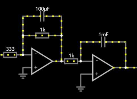
Figure 1. model of DC servo motor(volt in to angle out)
3. Servo drive system construction and controller optimization
3.1. Construction and analysis of PD control system
For the PD control system, a forward series PD controller, add a motor model and an output feedback circuit are required [7]. If the feedback resistance of the PD controller divided by its negative input resistance is equal to a, the inductance of the PD controller divided by its negative input resistance is equal to b, and the feedback resistance of the adder is equal to d, then the value of C in the closed-loop transfer function of the system (the transfer function of the controller ) is equal to d / ( a + bs ). Then for the closed-loop transfer function of the system, the error signal E ( S ) is obtained by subtracting the input signal R ( S ) from the feedback signal. Then error signal E(S) will transmit to the controller C ( S ), and output the input signal controller U ( S ). Then it is output to Y ( S ) through the controlled system P ( S ), and the output is returned to the input through the unit negative feedback. So the closed-loop transfer function is found: Y(S)/R(S)=P(S)C(S)/(1+P(S)C(S))
In order to perfect rapidity, accuracy, and stability of the system, OCTAVE is used to find parameters:
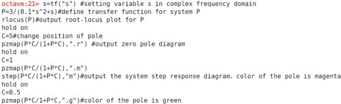
Figure 2. Code in OCTAVE
By observing the output diagram, it can be found that the response of green one is stable but too long. Then go back to the FALSTAD circuit for parameter fixed variable method debugging to find the optimal parameters is C=5S+100. After coding ( add C=5S+100,pzmap(P*C/1+P*C,”.m”) to the above program ). So far, the best figure for the system can be found according to d/(a+bs).
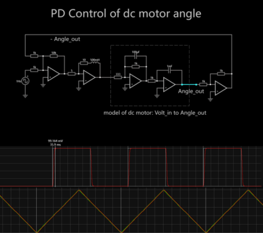
Figure 3. PD control system
3.2. Construction of PI control system
Only need to change the controller into PI controller on the basis of the PD control system [8]. As Figure.4.
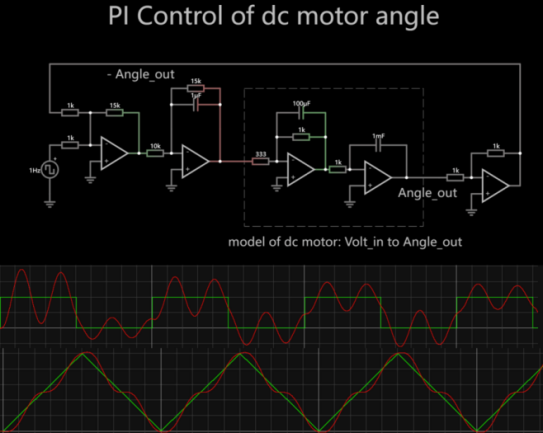
Figure 4. PI control system
3.3. Construction of PID control system
Only need to change the controller into PID controller on the basis of the PD control system [9]. As Figure.5.
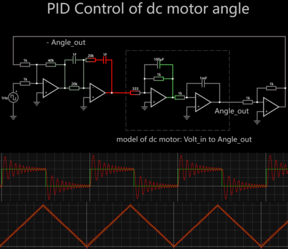
Figure 5. PID control system
3.4. Selection of control system and construction of breadboard
In each optimized control system, it can be found that the PD controller has the best tracking performance and response performance, which almost coincides with the waveform, and is most recommended for the servo DC motor. The PID controller’s tracking is also good, but the oscillation is too strong, which means that it can be barely used in this system. For the PI controller, it can only achieve approximate tracking and there is a certain degree of discreteness, which is not recommended for this system.
Therefore, it was decided to choose the PD controller, and begin to use TINKERCAD to build the circuit board according to the circuit of FALSTAD to start simulation [10]. As shown in Figure 6, it can be found that the built circuit board conforms to the simulated value and waveform mentioned in FALSTAD.
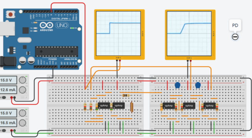
Figure 6. Circuit board for motor simulation
4. Conclusion
In order to create the control system and its simulation, this paper first suggests the RC circuit, which belongs to the first-order system, as the basis for the required designed system because of the similarities of both systems. Then, this paper uses partial formulas of electromechanics, physics, and electromagnetics to derive the transfer function of the servo DC motor model which has the function of a volt in to angle out and the transfer function of the system. After designing, the paper starts to build the whole system and modular it to build a closed loop transfer function. The next step is coding to determine the best value for each component in this system. After building the PD servo motor and perfecting its system, changing the controller to make the PI and PID control systems and perfecting each system to compare with each other to figure out that the PD controller is the best choice for this system, which has the function of the best tracking. The second recommended controller is the PID controller, which has the characteristic of oscillation tracking and can also track the input very well. The most recommended one for this system is PI controller. Then, the simulation will be used to apply PD control of the servo DC motor system to ensure it can be used in real life. There are still some weaknesses in this research, such as making this system retrench, the component to solve current loss is not involved. It is okay in this project because the output is for the motors which need volts to run, but for other products, which need current, this system needs to add appropriate voltage followers at every middle places to make sure that most current can still existed at the output. In future research, the goal is to make this system suit more products and have a filtering effect on interference signals.
References
[1]. X. Wang, W. Wang, L. Li, J. Shi and B. Xie. Adaptive Control of DC Motor Servo System With Application to Vehicle Active Steering. IEEE/ASME Transactions on Mechatronics, vol. 24, no. 3, pp. 1054-1063, June 2019, doi: 10.1109/TMECH.2019.2906250. 1054-1063.
[2]. S. K. Garakoui, E. A. M. Klumperink, B. Nauta, F. E. vanVliet. Frequency Limitations of First-Order gm−RC All-Pass Delay Circuits. IEEE, Transactions on Circuits and Systems II: Express Briefs, vol. 60, no. 9, Sept. 2013, doi: 10.1109/TCSII.2013.2268418. 572 – 576.
[3]. T Mizuno a, M Iwadare a, M Nanahara a K Koyama b, T Anzai b, M Nirei c, H Yamada a.Considerations on electrical and mechanical time constants of a moving-magnet-type linear DC motor. Sensors and Actuators A: Physical Volume 81, Issues 1–3, 1 April 2000.301-304
[4]. Emad Said Addasi. Modelling and simulation of dc electric drive control system with variable moment of inertia.January 2013,International Journal of Simulation: Systems, Science & Technology 4(1), DOI:10.5013/IJSSST.a.13.05.03.52-57.
[5]. F. Rodriguez, A. Emadi. A Novel Digital Control Technique for Brushless DC Motor Drives: Steady State and Dynamics. IECON 2006 - 32nd Annual Conference on IEEE Industrial Electronics, Paris, France, 2006, doi: 10.1109/IECON.2006.347838. 1545-1550.
[6]. Hong-Yi Huang, Bo-Ruei Wang and Jen-Chieh Liu. High-gain and high-bandwidth rail-to-rail operational amplifier with slew rate boost circuit. 2006 IEEE International Symposium on Circuits and Systems (ISCAS), Kos, Greece, 2006, pp. 4 pp.-, doi: 10.1109/ISCAS.2006.1692733. 907-910.
[7]. N. D. Cuong, T. X. Minh. Design of analog MRAS controllers using operational amplifiers for motion control systems. 2014 International Conference on Information Science, Electronics and Electrical Engineering, Sapporo, Japan, 2014, pp. 904-908, doi: 10.1109/InfoSEEE.2014.6947799. 904-908.
[8]. M. Kumngern and U. Torteanchai. CMOS programmable P, PI, PD and PID controller circuit using CCTAs. 2016 International Conference on Electronics, Information, and Communications (ICEIC), Danang, Vietnam, 2016, pp. 1-4, doi: 10.1109/ELINFOCOM.2016.7562929. 1-4.
[9]. E. A. Gonzalez, V. Alimisis, C. Psychalinos, A. Tepljakov. Design of a Generalized Fractional-Order PID Controller Using Operational Amplifiers. 2018 25th IEEE International Conference on Electronics, Circuits and Systems (ICECS), Bordeaux, France,2018, doi: 10.1109/ICECS.2018.8617954. 253-256.
[10]. L. Cederström and A. Graupner, Joint simulation of mixed-signal integrated circuits and printed circuit boards. Proceedings of the 19th International Conference Mixed Design of Integrated Circuits and Systems - MIXDES 2012. 364-369.
Cite this article
Tang,T. (2024). Construction and performance analysis of DC servo system based on operational amplifier. Applied and Computational Engineering,101,42-48.
Data availability
The datasets used and/or analyzed during the current study will be available from the authors upon reasonable request.
Disclaimer/Publisher's Note
The statements, opinions and data contained in all publications are solely those of the individual author(s) and contributor(s) and not of EWA Publishing and/or the editor(s). EWA Publishing and/or the editor(s) disclaim responsibility for any injury to people or property resulting from any ideas, methods, instructions or products referred to in the content.
About volume
Volume title: Proceedings of the 2nd International Conference on Machine Learning and Automation
© 2024 by the author(s). Licensee EWA Publishing, Oxford, UK. This article is an open access article distributed under the terms and
conditions of the Creative Commons Attribution (CC BY) license. Authors who
publish this series agree to the following terms:
1. Authors retain copyright and grant the series right of first publication with the work simultaneously licensed under a Creative Commons
Attribution License that allows others to share the work with an acknowledgment of the work's authorship and initial publication in this
series.
2. Authors are able to enter into separate, additional contractual arrangements for the non-exclusive distribution of the series's published
version of the work (e.g., post it to an institutional repository or publish it in a book), with an acknowledgment of its initial
publication in this series.
3. Authors are permitted and encouraged to post their work online (e.g., in institutional repositories or on their website) prior to and
during the submission process, as it can lead to productive exchanges, as well as earlier and greater citation of published work (See
Open access policy for details).
References
[1]. X. Wang, W. Wang, L. Li, J. Shi and B. Xie. Adaptive Control of DC Motor Servo System With Application to Vehicle Active Steering. IEEE/ASME Transactions on Mechatronics, vol. 24, no. 3, pp. 1054-1063, June 2019, doi: 10.1109/TMECH.2019.2906250. 1054-1063.
[2]. S. K. Garakoui, E. A. M. Klumperink, B. Nauta, F. E. vanVliet. Frequency Limitations of First-Order gm−RC All-Pass Delay Circuits. IEEE, Transactions on Circuits and Systems II: Express Briefs, vol. 60, no. 9, Sept. 2013, doi: 10.1109/TCSII.2013.2268418. 572 – 576.
[3]. T Mizuno a, M Iwadare a, M Nanahara a K Koyama b, T Anzai b, M Nirei c, H Yamada a.Considerations on electrical and mechanical time constants of a moving-magnet-type linear DC motor. Sensors and Actuators A: Physical Volume 81, Issues 1–3, 1 April 2000.301-304
[4]. Emad Said Addasi. Modelling and simulation of dc electric drive control system with variable moment of inertia.January 2013,International Journal of Simulation: Systems, Science & Technology 4(1), DOI:10.5013/IJSSST.a.13.05.03.52-57.
[5]. F. Rodriguez, A. Emadi. A Novel Digital Control Technique for Brushless DC Motor Drives: Steady State and Dynamics. IECON 2006 - 32nd Annual Conference on IEEE Industrial Electronics, Paris, France, 2006, doi: 10.1109/IECON.2006.347838. 1545-1550.
[6]. Hong-Yi Huang, Bo-Ruei Wang and Jen-Chieh Liu. High-gain and high-bandwidth rail-to-rail operational amplifier with slew rate boost circuit. 2006 IEEE International Symposium on Circuits and Systems (ISCAS), Kos, Greece, 2006, pp. 4 pp.-, doi: 10.1109/ISCAS.2006.1692733. 907-910.
[7]. N. D. Cuong, T. X. Minh. Design of analog MRAS controllers using operational amplifiers for motion control systems. 2014 International Conference on Information Science, Electronics and Electrical Engineering, Sapporo, Japan, 2014, pp. 904-908, doi: 10.1109/InfoSEEE.2014.6947799. 904-908.
[8]. M. Kumngern and U. Torteanchai. CMOS programmable P, PI, PD and PID controller circuit using CCTAs. 2016 International Conference on Electronics, Information, and Communications (ICEIC), Danang, Vietnam, 2016, pp. 1-4, doi: 10.1109/ELINFOCOM.2016.7562929. 1-4.
[9]. E. A. Gonzalez, V. Alimisis, C. Psychalinos, A. Tepljakov. Design of a Generalized Fractional-Order PID Controller Using Operational Amplifiers. 2018 25th IEEE International Conference on Electronics, Circuits and Systems (ICECS), Bordeaux, France,2018, doi: 10.1109/ICECS.2018.8617954. 253-256.
[10]. L. Cederström and A. Graupner, Joint simulation of mixed-signal integrated circuits and printed circuit boards. Proceedings of the 19th International Conference Mixed Design of Integrated Circuits and Systems - MIXDES 2012. 364-369.