


1. Introduction
With the rapid development of information technology, devices are becoming smaller and more powerful. In the post-PC era, new devices represented by smart terminals and smartphones are gradually replacing traditional desktop computers and laptops. These new smart terminals, integrating computing and communication, demand lower power consumption, smaller size, and multiple communication methods for information exchange. As one of the main short-range, low-power wireless communication technologies, Bluetooth has been widely applied in the field of information exchange and transmission [1].
With the rapid advancement of IoT technology, wireless communication and remote control play a crucial role in smart devices and robotic applications. Bluetooth technology, as a short-range wireless communication technology, is widely used in various fields, including remote-controlled cars. Remote-controlled cars, a common robotic application, have significant educational and entertainment value.
This paper aims to design and implement a Bluetooth remote-controlled car system based on the ESP32, achieving remote control and monitoring through Bluetooth communication technology. As a powerful development board, the ESP32 integrates Wi-Fi and Bluetooth functionalities, characterized by high performance and low power consumption, making it ideal for IoT applications.
In this paper, I will introduce the design and implementation process of the Bluetooth remote-controlled car system. First, I will elaborate on the Bluetooth functionalities and working principles of the ESP32, including classic Bluetooth and Bluetooth Low Energy (BLE). Then, I will introduce the hardware design and assembly of the car, including the wiring and working principles of the DC motor drive module, Bluetooth module, and speed measurement module.
Next, I will describe in detail how to use the ESP32 to communicate with the Bluetooth module, including establishing a Bluetooth connection, sending and receiving data, etc. I will explain how to remotely control the car's movements through a Bluetooth connection, including moving forward, backward, left turn, and right turn. Additionally, I will introduce how to use the speed measurement module to monitor the car's speed in real-time and perform feedback control.
To evaluate the system's performance, I will conduct a series of experiments and analyze the results. I will explore the application of the PID control algorithm in car speed control and discuss how to adjust PID parameters to achieve better control performance. Moreover, I will study performance indicators such as overshoot, settling time, and steady-state error of the system.
Finally, I will summarize the work of this paper and propose future work directions. I will discuss how to further improve the system's functionality and performance, such as adding obstacle avoidance functions and optimizing control algorithms.
2. Overall System Design
In implementing the Bluetooth remote-controlled car system based on the ESP32, it is divided into five modules: remote control device module, ESP32 main control module, motor drive module, power management module, sensor module, and PID adjustment module.
Remote Control Device Module: The remote control device is the user's control apparatus, which can be a smartphone, tablet, or dedicated remote control. The remote control device communicates with the ESP32 via Bluetooth, transmitting the user's commands to the ESP32 to control the car's movement.
ESP32 Main Control Module: The ESP32 main control module is the core of the entire system, responsible for receiving commands from the remote control device and controlling the car's movement. It includes the ESP32 development board and corresponding circuit connections, used to connect various modules and execute control algorithms.
Motor Drive Module: The motor drive module is responsible for driving the car's motors, controlling movements such as forward, backward, left turn, and right turn. It receives command signals from the ESP32 and converts these signals into motor actions to control the car.
Power Management Module: The power management module provides stable power supply for the entire system, including the ESP32 main control module and motor drive module. It may include batteries, power adapters, and power management circuits to ensure the system's normal operation. In this experiment, the power management module is realized through batteries.
Sensor Module: The sensor module can include a speed measurement module and other sensors, used to obtain information about the car's speed, position, and environment. The speed measurement module measures the rotation speed of the car's wheels to achieve speed control and position feedback.
PID Adjustment Module: The PID adjustment module ensures that the car's speed reaches stability, forming a closed-loop control system.
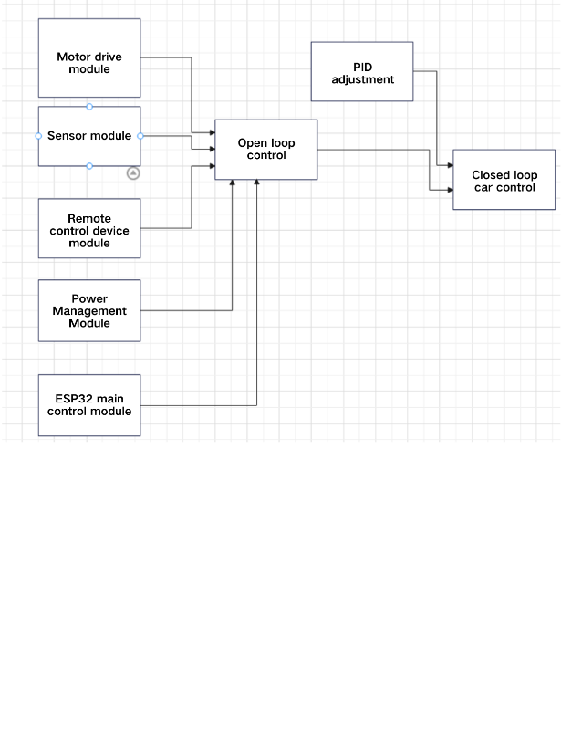
Figure 1. Overall Workflow of the Car
3. Hardware Connections and Principles
3.1. Working Principle and Wiring of the MX1919 DC Motor Driver Module
3.1.1. Working Principle of the MX1919 DC Motor Driver Module
The MX1919 DC motor driver module operates on the principle of an H-bridge driver, which can achieve forward rotation, reverse rotation, and braking functions for a DC motor [2]. It typically consists of the following key components:
H-Bridge Circuit: The H-bridge circuit is composed of four switches (usually MOSFETs) connected to the two terminals of the DC motor. By controlling the on/off states of these four switches, the direction of current flow can be changed, thus achieving forward and reverse rotation of the motor.
Control Logic Circuit: The control logic circuit receives external signals and generates corresponding control signals to manage the switching states of the H-bridge circuit. Typically, the control logic circuit receives signals from the main controller (such as the ESP32) or other control devices and controls the motor's direction and speed based on the logical state of these signals.
3.1.2. Wiring of the MX1919 DC Motor Driver Module
Connecting the Power Supply:
Connect the power pins of the driver module (usually marked VCC and GND) to an external power supply. Ensure that the voltage range of the power supply meets the requirements of the driver module.
Connecting the Motor:
Connect the two terminals of the DC motor to the two motor output interfaces on the driver module (usually marked M1 and M2). Ensure that the motor's connection polarity matches the interface polarity of the driver module. If the motor's rotation direction does not match the expectation, swap the motor's terminal connections.
Connecting Control Signals:
Connect the control pins of the driver module (usually marked IN1, IN2, IN3, and IN4) to the GPIO pins of the main controller (such as the ESP32). By controlling the logical states (high or low) of the GPIO pins, you can control the switching states of the H-bridge circuit in the MX1919 driver module, thus controlling the motor's rotation direction and operating state.
3.2. Principle of ESP32 Bluetooth BLE Communication
The most critical part of the Bluetooth transmission system is the realization of BLE communication functionality. BLE communication follows the same principle as traditional Bluetooth communication, where a Bluetooth master device uses a Bluetooth chip to enable devices to send and receive radio signals over short distances to find a Bluetooth slave device [3].
When using ESP32 for Bluetooth BLE communication, it is a low-power wireless communication technology suitable for IoT devices and sensors. The ESP32 integrates a complete BLE protocol stack, including the physical layer, link layer, host controller interface (HCI), and general attribute (GATT) protocol modules. The BLE communication process includes broadcasting, scanning, and connecting operations, managed by the GAP (Generic Access Profile) module. The GATT protocol defines data transmission methods between BLE devices, including concepts such as services, characteristics, and descriptors. The ESP32 provides a BLE library that simplifies the process of creating BLE services, characteristics, and descriptors for developers. The ESP32 Bluetooth BLE communication offers advantages such as low power consumption, fast connection, and simplified data transmission methods, making it suitable for IoT applications, sensor data collection, and remote control scenarios. This technology's widespread application provides strong support for the development of the IoT field.
3.3. Working Principle and Wiring of the DC Motor
3.3.1. Working Principle of the DC Motor
The working principle of a DC motor is based on the generation of torque by current in a magnetic field. By controlling the direction and magnitude of the current, forward and reverse rotation of the DC motor can be achieved. When rotating forward, the interaction between the current and the magnetic field generates rotational torque; when rotating in reverse, the interaction generates torque in the opposite direction [4]. Control methods include changing the current direction, altering the voltage polarity, and using external circuits and drivers.
3.3.2. Wiring of the DC Motor
1. Connect the positive terminal (+) of the power supply to the positive terminal (+) of the DC motor.
2. Connect the negative terminal (-) of the power supply to the negative terminal (-) of the DC motor.
3. Connect the control signal lead to the output end of the controller or driver to control the motor's movement.
 Figure 2. Overall Wiring Diagram of the DC Motor
4. Software Design
The system software concerns the reliability and applicability of the system. To optimize the software, the following two points need to be focused on during the design process:
High Integration: To meet the demands of low-cost innovation, the system space needs to be minimized as much as possible, allowing limited units to accommodate an unlimited number of module circuits. This requires a rational overall layout design in the system solution, where identical network interfaces should be placed together to reduce safety distances. Heat-generating components should be close to heat sinks and edges to facilitate heat conduction, thereby improving product reliability. Considering these factors, modular units should be designed to reduce system control complexity and promote integration, which helps reduce design and maintenance costs.
4.1. How to Control the Car’s Forward, Backward, Left Turn, Right Turn, and Straight Line Movement
4.1.1. Controlling the Car’s Forward, Backward, Left Turn, and Right Turn
Forward: Simultaneously rotate both drive motors in the same direction and at the same speed to move the car forward. The control signals should cause the motors to rotate forward.
Backward: Simultaneously rotate both drive motors in the reverse direction and at the same speed to move the car backward. The control signals should cause the motors to rotate in reverse.
Left Turn: Stop or slow down the left drive motor while the right drive motor rotates forward to turn the car left. The control signals should stop or slow down the left motor and rotate the right motor forward.
Right Turn: Stop or slow down the right drive motor while the left drive motor rotates forward to turn the car right. The control signals should stop or slow down the right motor and rotate the left motor forward.
In the code, forward movement is implemented as follows:
void Forward() {
ledcWrite(2, PWM_Left);
ledcWrite(1, 0);
ledcWrite(3, PWM_Left);
ledcWrite(4, 0);
}
For backward, left turn, and right turn, adjust the positions of PWM_Left and PWM_Right accordingly.
4.1.2. Controlling the Car to Move in a Straight Line
PID control, a classic control method, is widely used in industrial control to ensure the normal operation of industrial processes [5]. In this experiment, PID control is used to make the car move in a straight line. The PID controller adjusts the control signal based on the current error (the difference between the actual value and the target value) using proportional, integral, and derivative terms to keep the car on a straight path. The basic steps to control the car in a straight line using a PID controller are as follows:
Set the Target Value: Determine the target position or direction when the car moves in a straight line. This can be a specific position coordinate or direction angle.
Get Feedback Signal: Use sensors (such as encoders or gyroscopes) to obtain feedback signals of the car's current position or direction.
Calculate Error: Compare the target value with the actual feedback signal to calculate the current error. The error can be position deviation, direction deviation, or a combination of both.
Set PID Parameters: Adjust the proportional (P), integral (I), and derivative (D) coefficients of the PID controller. The choice of these parameters depends on the car's characteristics and control system requirements.
Calculate Control Signal: Use the PID formula to calculate the control signal based on the current error and PID parameters. The control signal can represent the motor speed or the output of the motor driver.
Apply Control Signal: Apply the calculated control signal to the drive motors to adjust their speed or direction, making the car move towards the target straight line.
Continuous Update: Continuously obtain feedback signals, calculate errors, compute control signals, and periodically update controller parameters to keep the car on the straight path.
4.2. Design of Single Closed-Loop DC Speed Control System
Controller Design: Design a PID controller to regulate the speed. The PID controller consists of proportional (P), integral (I), and derivative (D) components. It generates control signals by calculating the weighted sum of current and historical errors. The selection and adjustment of PID parameters are crucial for system performance.
Feedback Signal Processing: Obtain feedback signals of motor speed through sensors and compare them with the target speed. Calculate the error signal based on the comparison results, which serves as the input to the PID controller.
Control Signal Generation: The PID controller calculates the corresponding control signal based on the error signal, usually represented as motor input voltage or duty cycle. The method of generating control signals may vary depending on the characteristics of the motor driver and control requirements.
Output Signal Conversion: Convert the control signal into a form suitable for the motor driver to achieve motor control. This may involve voltage conversion, current amplification, or using PWM (pulse-width modulation) techniques.
Closed-Loop Control: Feed the output signal back into the feedback loop, compare it with the target speed to achieve closed-loop control. Continuously adjust the control signal to make the actual motor speed gradually approach the target speed.
Stability and Performance Optimization: Optimize the system's stability and performance, such as through appropriate PID parameter adjustment, filter design, saturation limits, and enhanced anti-interference capabilities.
void ComputeSpeed() {
Speed_Left=counter_left/40.0/0.4*60;
counter_left=0;
Speed_Right=counter_right/40.0/0.4*60;
counter_right=0;
PWM_Left=LeftComputePID();
PWM_Right=RightComputePID();
}
4.3. PID Parameter Tuning
In this experiment, manual tuning was chosen for PID parameter adjustment through a trial-and-error method. Initially, set the P, I, and D parameters to small values. Gradually increase the P parameter and observe the system's response. Increasing the P parameter can enhance the system's response speed, but an excessive P value may cause system instability. Next, gradually increase the I parameter and observe the system's overshoot and steady-state error. Finally, gradually increase the D parameter and observe the system's anti-interference capability and stability. Through iteration and fine-tuning, an appropriate combination of PID parameters was found [6]. The final suitable combination was kp = 0.4, ki = 0.3, kd = 0.1. The overshoot ranged from 2.5 to 7, the settling time was around 10 seconds, and the steady-state error ranged from 2% to 5.83%.
4.4. Software Flowchart
Based on the system design in the previous chapters, the software flowcharts are drawn as shown in Figure 3 for PID software, Figure 4 for controlling the car’s forward, backward, left turn, and right turn, and Figure 5 for controlling the car to move in a straight line.

Figure 3. PID Software Flowchart


Figure 4. Flowchart for Controlling the Car’s Forward, Backward, Left Turn, and Right Turn
Figure 5. Flowchart for Controlling the Car to Move in a Straight Line
5. Conclusion
During the debugging process, the main issue encountered was the instability of the car's Bluetooth signal connection, which caused the PID control to fail when the Bluetooth connection was lost. It was eventually found that connecting the car to the computer via USB significantly improved the stability of the Bluetooth signal, effectively resolving this issue.
This experiment profoundly demonstrated the importance and broad application prospects of Bluetooth Low Energy (BLE) technology. The ESP32, as a powerful development board, integrates rich Bluetooth functionalities, including BLE communication. Using the ESP32's BLE capabilities, stable wireless communication with a mobile phone was successfully achieved, making the phone the car’s remote controller. Additionally, an in-depth understanding of the ESP32's programming and development environment was gained, and the use of the Arduino IDE and the ESP32 development library simplified the coding process. The versatility and libraries provided by the ESP32 enabled the rapid development of a highly controllable Bluetooth remote control car.
Moreover, the practice highlighted the importance of correctly designing hardware circuits and wiring. Ensuring proper connection and configuration of the MX1919 DC motor driver module, Bluetooth module, and other related components is crucial for signal transmission and power supply stability, directly affecting the system's overall performance. Additionally, this practice explored the theory and application of PID controllers. Through appropriate PID parameter adjustment and optimization, stable straight-line driving of the car was achieved, significantly enhancing the system's response speed and accuracy. Although debugging and optimizing the PID controller requires patience and experimentation, the final control effect is satisfactory.
Acknowledgement
Yuhe Tie and Peiming Chen: Conceptualization, Methodology, Software, Resources, Writing- Original draft preparation, Visualization, Investigation.
References
[1]. Niu Yufeng. Research on Enhancing Bluetooth Data Transmission Performance and Chip Implementation Technology. Xidian University, 2012.
[2]. Zhang Dongqing. Design of a DC Servo Motor Driver. Hangzhou Dianzi University, 2012.
[3]. Luo Fucai. Research and Implementation of Bluetooth Communication System Based on Android Platform [D]. North China Electric Power University, 2013.
[4]. Zhong Yuexian, Lin Heng. Computer Control of Mechanical Systems. Tsinghua University Press, 2001-8-1.
[5]. Huang Yiqing. Research on PID Controller Parameter Tuning and Its Application [D]. Anhui University of Science and Technology, 2009.
[6]. Zhang Heng. Research on Sensorless Vector Control Technology of Electric Tail Rotor for Unmanned Helicopter. University of Electronic Science and Technology of China, 2020.
Cite this article
Tie,Y.;Chen,P.;Ma,Y. (2024). BLE Bluetooth remote-controlled car based on ESP32. Applied and Computational Engineering,81,25-32.
Data availability
The datasets used and/or analyzed during the current study will be available from the authors upon reasonable request.
Disclaimer/Publisher's Note
The statements, opinions and data contained in all publications are solely those of the individual author(s) and contributor(s) and not of EWA Publishing and/or the editor(s). EWA Publishing and/or the editor(s) disclaim responsibility for any injury to people or property resulting from any ideas, methods, instructions or products referred to in the content.
About volume
Volume title: Proceedings of the 2nd International Conference on Machine Learning and Automation
© 2024 by the author(s). Licensee EWA Publishing, Oxford, UK. This article is an open access article distributed under the terms and
conditions of the Creative Commons Attribution (CC BY) license. Authors who
publish this series agree to the following terms:
1. Authors retain copyright and grant the series right of first publication with the work simultaneously licensed under a Creative Commons
Attribution License that allows others to share the work with an acknowledgment of the work's authorship and initial publication in this
series.
2. Authors are able to enter into separate, additional contractual arrangements for the non-exclusive distribution of the series's published
version of the work (e.g., post it to an institutional repository or publish it in a book), with an acknowledgment of its initial
publication in this series.
3. Authors are permitted and encouraged to post their work online (e.g., in institutional repositories or on their website) prior to and
during the submission process, as it can lead to productive exchanges, as well as earlier and greater citation of published work (See
Open access policy for details).
References
[1]. Niu Yufeng. Research on Enhancing Bluetooth Data Transmission Performance and Chip Implementation Technology. Xidian University, 2012.
[2]. Zhang Dongqing. Design of a DC Servo Motor Driver. Hangzhou Dianzi University, 2012.
[3]. Luo Fucai. Research and Implementation of Bluetooth Communication System Based on Android Platform [D]. North China Electric Power University, 2013.
[4]. Zhong Yuexian, Lin Heng. Computer Control of Mechanical Systems. Tsinghua University Press, 2001-8-1.
[5]. Huang Yiqing. Research on PID Controller Parameter Tuning and Its Application [D]. Anhui University of Science and Technology, 2009.
[6]. Zhang Heng. Research on Sensorless Vector Control Technology of Electric Tail Rotor for Unmanned Helicopter. University of Electronic Science and Technology of China, 2020.