


1. Introduction
As a cornerstone of the fourth generation (4G) and a critical component of the fifth generation (5G) standards, Long Term Evolution (LTE) has been formalized by the 3rd Generation Partnership Project (3GPP) to meet the high demands of modern mobile communication systems. Leveraging Orthogonal Frequency Division Multiplexing (OFDM) and Multiple Input Multiple Output (MIMO), LTE offers numerous advantages such as higher system efficiency, lower latency, and a unified network architecture [1-2]. MIMO, a core technology in 5G wireless communication, utilizes multiple antennas for simultaneous data transmission and reception, enabling the concurrent transmission of multiple data streams over the same time and frequency resources, thereby enhancing data processing efficiency, spectral efficiency, and connection reliability [3-4].
However, MIMO also presents challenges, primarily due to interference. When multiple signals are transmitted across multiple antennas, mutual interference can occur, negatively impacting performance. Environmental factors also affect MIMO performance. Typically, matrix inversion is required to resolve received signals, and this process is exceedingly complex for larger matrices, introducing high computational complexity. Traditional methods for solving received signals each have their strengths and weaknesses. The Maximum Likelihood (ML) method searches all possible combinations of transmitted signal vectors to find the one that best matches the received signal under the given channel matrix. While highly accurate, the computational complexity increases exponentially with the dimension of the vector, making it impractical for high-dimensional matrices and vectors [5]. The Sphere Decoding (SD) method searches for the optimal solution within a spherical region centered on the received signal with a specified radius, reducing the search space while maintaining high accuracy. Nonetheless, it still heavily relies on the channel matrix [6]. Due to the high complexity of nonlinear detection methods, linear detection methods are often preferred. The Zero-Forcing (ZF) method seeks a linear transformation to directly solve for the transmitted signal at the receiver in the absence of noise. However, ZF performance degrades significantly when the condition number of the channel transmission matrix is high [7]. The MMSE technique aims to minimize the mean square error for signal estimation by considering both interference and noise, providing better stability. Yet, MMSE involves large-scale matrix inversion and is highly dependent on the channel, presenting several practical limitations [8].
In this paper, we analyze several typical methods and their circuit architectures for solving detection signals in MIMO systems. Based on the detection algorithms and circuit structures, we categorize them into three types: the ADMM method [9], the Neumann Series (NS) method [10-14], and iterative methods [15-19]. The ADMM method decomposes a complex optimization problem into more manageable subproblems and iteratively updates them in an alternating fashion to gradually approach the optimal solution, making it suitable for scenarios where the base stations’ quantities are nearly equivalent to the users’ quantities. The NS method approximates the inverse of a matrix by its series expansion, thus reducing the computational complexity associated with direct matrix inversion and approximating the signal to be detected. For its circuit architecture, it usually involves parallel operations of matrix addition and multiplication. The iterative method consists of three components: an iterative expression, an initial value, and a step size. By setting different values for these components, various iterative methods can be derived and applied to different scenarios. Due to iterative calculations, its circuit architecture is generally more complex, involving numerous adders, multipliers, and storage modules.
The rest of the paper is organized as follows: Section II presents a concise introduction to the preliminaries of Massive MIMO and traditional linear signal detection methods. Section III describes ADMM used in MIMO and its VLSI architecture. The detailed NS method and iterative methods are proposed in Section IV and V respectively, with corresponding circuit architecture. In Section VI, the final conclusions are presented.
2. Preliminaries
2.1. Massive MIMO uplink system model
In an uplink multi-user MIMO (MU-MIMO) system, the base station (BS) is outfitted with \( N \) antennas, which simultaneously serve \( M \) users at the user end. Typically, we have \( N≥M \) . For each user at the user end, the transmitted information is encoded into a transmission vector \( s \) , \( s=[{s_{1}},{s_{2}},…,{s_{M}}] \) . By modeling \( s \) , we can derive its linear expression in a wireless MIMO system, as shown below:
\( y=Hs+n \) (1)
where \( y=[{y_{1}},{y_{2}},…,{y_{N}}]∈{C^{N}} \) denotes the signal vector received at the BS, \( H∈{C^{N×M}} \) denotes the Rayleigh flat-fading channel matrix and \( n∈{C^{N}} \) represents the additive white Gaussian noise (AWGN) characterized by a zero mean and a specified variance.
By utilizing the known received signal \( y \) at the base station and the known channel matrix \( H \) , we can solve for the transmitted signal \( s \) .
2.2. Linear detection methods
For massive MIMO, traditional techniques for linear signal detection include ZF and MMSE. The ZF method employs the pseudo-inverse of the channel matrix to eliminate multi-user interference. By using pre-processing and post-processing matrices, the interference signals are forced to zero, thereby achieving the decoupling of user signals.
In the expression, ZF does not consider the noise vector \( n \) . As a consequence, the equalization of transmitted vector \( s \) could be updated as:
\( {s_{ZF}}={H^{t}}y={({H^{H}}H)^{-1}}{H^{H}}y \) (2)
where \( {H^{t}} \) denote the pseudo-inverse of \( H \) , \( {H^{H}} \) denote the conjugate transpose of \( H \) , which is tantamount to inverting the Gram matrix, namely \( {G_{ZF}}{=H^{H}}H \) .
In the MMSE method, we first perform channel estimation using pilot signals to attain the channel matrix \( H \) . Subsequently, in accordance with the channel matrix and noise variance \( {σ^{2}} \) , we compute the receive matrix \( W \) which aims to minimize the mean square error between the received signals and the transmitted signals. Finally, using the received signal \( y \) and the receive matrix \( W \) , we obtain the recovered transmitted signal \( {s_{MMSE}} \) , which is expressed as follows:
\( {s_{MMSE}}={({H^{H}}H+{σ^{2}}{I_{A}})^{-1}}{H^{H}}y \) (3)
where \( {I_{A}} \) denote the \( A×A \) identity matrix. In MMSE method, the Gram matrix can be modified with the introduction of noise variance \( σ \) , namely \( {G_{MMSE}}={H^{H}}H+{σ^{2}}{I_{A}} \) .
3. ADMM-Based Infinity-Norm Detection
3.1. The signal detection algorithm
The ADMM is an iterative algorithm employed for solving constrained optimization problems. It is frequently utilized in convex optimization problems, which are defined by a convex constraint set and a convex objective function. The ADMM algorithm functions by decomposing the convex optimization problem into a series of subproblems. and alternately updating the variables to progressively approach the optimal solution.
The ADMM problem is scaled and can be expressed as:
\( \begin{matrix}{s^{k+1}}=arg\underset{s}{min}{\lbrace f(s)+\frac{ρ}{2}∥s-{z^{k}}+{u^{k}}∥_{2}^{2}\rbrace } \\ {z^{k+1}}=\prod _{C}({s^{k+1}}+{u^{k}}) \\ {u^{k+1}}={u^{k}}+{s^{k+1}}-{z^{k+1}} \\ \end{matrix} \) (4)
where \( u \) is the scaled dual variable and \( {∥s∥_{2}} \) represent the \( {l_{2}} \) -norm of vector \( s \) . Supposed that \( v={s^{k+1}}+{u^{k}} \) , then \( \prod _{C}(v) \) can be formulated as an equation: \( \prod _{C}(v)=arg\underset{z}{min}{\lbrace g(z)+\frac{ρ}{2}∥z-v∥_{2}^{2}\rbrace } \) [20].
By introducing the infinity-norm, and during the initial phase of the ADMM iteration process, under the condition of fixing \( z \) , we obtain the result of minimizing \( s \) by taking the partial derivative of the corresponding augmented Lagrangian with respect to \( s \) and setting the partial derivative to zero. The expression is:
\( \hat{s}={({H^{H}}H+βI)^{-1}}({H^{H}}y+β(z-λ)) \) (5)
where variable \( λ \) is the scaled dual variable that corresponds to the constraint \( z=s \) , and \( β \gt 0 \) is a regularization parameter chosen appropriately.
In this expression, the Gram matrix could be updated as \( {G_{ADMM}}={H^{H}}H+βI \) and \( {y_{MF}}={H^{H}}y \) means a matched filter.
Since the ADMM method involves decomposing a large optimization task into multiple sub-tasks and solving these sub-tasks, it is only suitable for scenarios where the base station antennas’ quantities are nearly equivalent to the users’ quantities. When the base station antennas’ quantities significantly exceed the users’ quantities, the results become less accurate.
3.2. VLSI architecture
In this section, we propose an ADMM-based infinite norm circuit architecture, which is primarily divided into two parts: the vector multiplication computation unit and the matched filter update unit. The detailed implementation process is described as follows.
Firstly, the vector multiplication computation unit (VM unit) is designed to minimize the variable \( s \) in the algorithm. The architecture of this module is illustrated in Figure 1 and primarily consists of complex multipliers and adder trees. In the preliminary stage, the VM unit calculates the matched filter (MF) and stores the resulting data in a register array. Concurrently, the matrix \( H \) is retained within a conventional cell-based memory structure, and the \( \widetilde{L} \) which denotes the lower triangular matrix is stored in another standard cell-based triangular memory [21]. Subsequently, the matrix \( \widetilde{L} \) is utilized to calculate \( \widetilde{L}{y^{MF}} \) with the results being stored in a temporary register array \( t \) . The following operation involves performing the product between \( t \) and \( \widetilde{d} \) . The lower triangular memory is read to compute \( {\widetilde{L}^{H}}t \) , yielding the \( \hat{s} \) for different users, which constitutes the final output of the VM module.
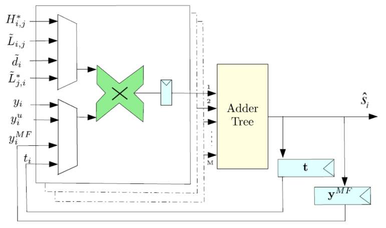
Figure 1. Architecture of VM unit [9].
The second part is the MF update unit (MFU unit), which is responsible for minimizing \( z \) and updating \( λ \) . The architecture is shown in Figure 2. The initial value of \( λ \) is set to zero and stored in a register. The Proj module compares \( {λ_{i}} \) and \( {\hat{s}_{i}} \) , producing \( \hat{z} \) as the output. The difference between \( \hat{z} \) and \( {\hat{s}_{i}} \) , scaled by the coefficient \( γ \) , is held in a register. The next state of \( {λ_{i+1}} \) is obtained by adding \( {λ_{i}} \) and the value \( γ({\hat{s}_{i}}-\hat{z}) \) stored in the register. The difference between \( {λ_{i+1}} \) and \( \hat{z} \) , multiplied by the parameter \( β \) , is stored in a register. This value is then added to the \( y_{i}^{MF} \) output to produce the final result, denoted as \( y_{i}^{u} \) . The value of \( y_{i}^{u} \) is fed back into the VM unit for subsequent iterations.
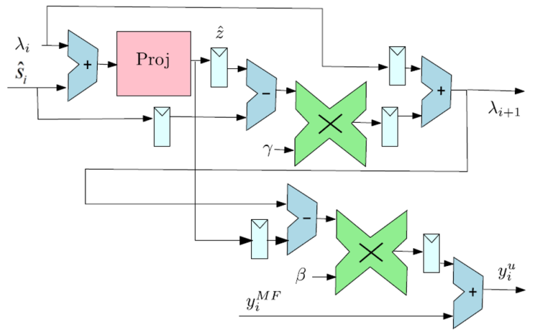
Figure 2. Architecture of MFU unit [9].
4. Neumann Series Method
The NS serves as an expansion method for approximating the inverse or pseudo-inverse of a matrix. This approach is highly effective in large-scale MIMO systems and other applications requiring efficient linear detection. The fundamental idea is to represent the matrix inverse as the sum of a convergent infinite series, thereby circumventing the significant computational burden of direct matrix inversion.
4.1. Detection algorithm
For basic NS method, if the receive matrix \( W \) is nearly equivalent to a matrix \( X \) which is invertible, namely:
\( \underset{n→∞}{lim}{{(I-{X^{-1}}W)^{n}}=0} \) (6)
then the inversion of matrix \( W \) can be expressed with the initial \( k \) terms of the Neumann series. As a consequence, the \( k \) -term approximation of the matrix \( {W^{-1}} \) can be obtained:
\( {W^{-1}}≈\sum _{n=0}^{k-1}{(I-{X^{-1}}W)^{n}}{X^{-1}} \) (7)
To ensure the convergence of Equation (7), the eigenvalues of matrix \( (I-{X^{-1}}W) \) must satisfy the condition that the absolute value of the largest eigenvalue \( λ \) is less than 1.
Given that \( W \) is diagonally dominant, it can be decomposed as \( W=D+E \) , where \( D \) represents the main diagonal of \( W \) and \( E \) denotes the off diagonal part of \( W \) . We consider \( X=D \) , then Equation (7) can be reformulated as follows:
\( {W^{-1}}=\sum _{n=0}^{k-1}{(-{D^{-1}}E)^{n}}{D^{-1}} \) (8)
Additionally, there are many expands on its applications. Firstly, in Gauss-Seidel Method, the new initial solution \( {s^{(0)}} \) could be replaced by the first 2 terms of NSE, namely \( {s^{(0)}}=W_{2}^{-1}{y^{MF}}={D^{-1}}-{D^{-1}}E{D^{-1}}{y^{MF}} \) .
Furthermore, in specific applications, choosing solely the diagonal elements might lead to a slower convergence rate of the matrix series or potentially cause it to diverge. Therefore, adjustments are necessary. Typically, a tridiagonal matrix can be used in place of a diagonal matrix, and combined with the NS for computation. Consequently, the matrix \( X \) can be updated as \( X={diag_{0}}(Z)+\sum _{l=1}^{{N_{0ff}}}{diag_{l}}(Z) \) , where \( {N_{0ff}} \) denotes the total count of off-diagonal and main diagonal elements, including the main diagonal elements, and \( {diag_{l}}(Z) \) has the same dimensions as \( Z \) like:
\( {[{diag_{l}}(Z)]_{i,j}}=\begin{cases} \begin{array}{c} {Z_{i,j}}, if|i-j|=l \\ 0,otherwise \end{array} \end{cases} \) (9)
4.2. VLSI architecture
For basic NS method, we assume \( M=-{D^{-1}}E \) and \( N={D^{-1}} \) , then the architecture is shown in Figure 3. After the matrix \( H \) passes through a systolic array in a lower triangular configuration, it is added to the product of \( {N_{0}} \) and the identity matrix \( I \) . The inverse of this sum is then taken to obtain \( {D^{-1}} \) , which we denote as \( N \) . By taking the negative of \( {D^{-1}} \) and multiplying it with \( E \) , we obtain \( M \) . Both \( N \) and \( M \) are then fed into subsequent modules for further computations.
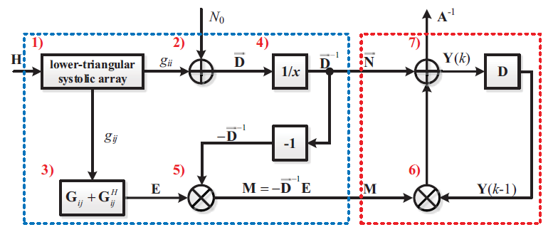
Figure 3. Architecture of the basic Neumann series method [11].
In the GS method utilizing Neumann series, the circuit architecture contains several components: the preprocessing unit, the GS unit, the NSE unit, and subsequent computation units, shown in figure 4. In the preprocessing module, calculations of \( {y^{MF}} \) , \( {G_{H}} \) , and \( {L_{H}} \) are performed. In the GS module, computations are carried out according to the GS algorithm. In the NSE module, the matrix \( D \) is first inverted, then negated, and multiplied by \( E \) . The resulting product is then multiplied by \( {D^{-1}} \) and finally assigned to \( {s^{(0)}} \) for subsequent computations.
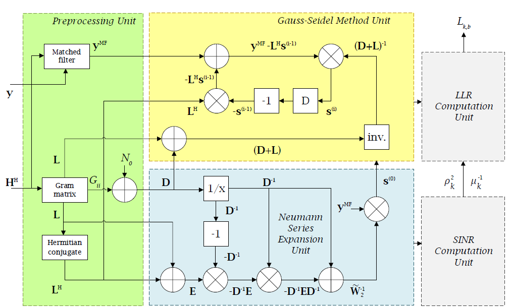
Figure 4. Architecture of Neumann series in Gauss-Seidel Method [12].
In the context of using Neumann series for tridiagonal matrices, additional computations and storage for certain elements on the diagonal are incorporated beyond the general calculations mentioned earlier. The schematic representation of this process is illustrated in Figure 5.
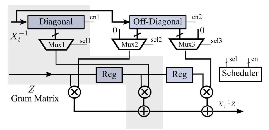
Figure 5. Architecture of Neumann series incorporated in tridiagonal matrices [13].
5. Iterative Method
In the application of MIMO systems, complex environments are often encountered, wherein various iterative methods reveal their superiority. Iterative methods exhibit excellent numerical stability and can utilize different iterative expressions, initial values, and step sizes for signal detection under diverse conditions, thereby ensuring high accuracy.
5.1. Iterative algorithm
In this paper, we will introduce two representative iterative algorithms: the quasi-Newton family algorithms and the Stair Matrix-Based Gauss-Seidel method.
Among the quasi-Newton family algorithms, one with relatively low computational complexity is the Barzilai-Borwein (BB) method [22]. By refining this method, we can derive the following iterative expression:
\( {s_{k+1}}={s_{k}}-\frac{(A{d_{k}}\cdot {d_{k}})}{({d_{k}}\cdot {d_{k}})}{g_{k}} \) (10)
in which \( {s_{k}} \) is the outcome of the \( k \) -th iteration of the transmitted signal, \( {d_{k}} \) represents the search direction, and \( A \) stands for the Hessian matrix.
In addition, another commonly used iterative method for signal detection is the Stair Matrix Based Gauss-Seidel Method. The initial value is set to \( {\hat{s}_{(0)}}={S^{-1}}{\hat{s}^{MF}} \) , where \( S \) is the stair matrix shown in figure 6.
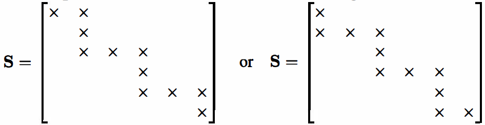
Figure 6. The stair matrix [18].
The iterative expression of this method is given by
\( {\hat{s}_{t}}={S^{-1}}((S-G){\hat{s}_{t-1}}+{\hat{s}^{MF}}) \) (11)
where \( G=D+L+R \) , \( D \) represents the diagonal elements, \( L \) denotes the lower triangular elements, and \( R \) represents the upper triangular elements. This iterative expression reduces computational complexity and effectively approximates the true solution.
5.2. VLSI architecture
In the QN iterative algorithm, the circuit architecture is fundamentally segmented into two components: the preprocessing module and the iterative module, as illustrated in Figure 7. In the preprocessing module, the Matched Filter, Gram Matrix, and Noise Power are calculated and then passed to the iterative module. Within the iterative module, the values of \( s \) , \( g \) , and \( d \) are iteratively updated according to the iterative expression until they approximate the true solution.
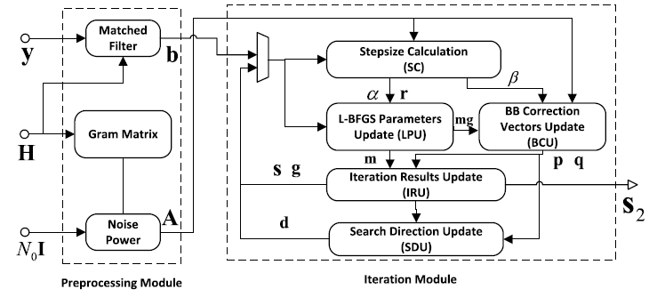
Figure 7. Architecture of QN iterative method [15].
In the Stair Matrix Based Gauss-Seidel Method, the matrices \( S \) , \( S-G \) , and Matched Filter are computed and processed before being passed into the Multiplier Array and Adder Tree modules. Finally, the final result is output, as illustrated in Figure 8.
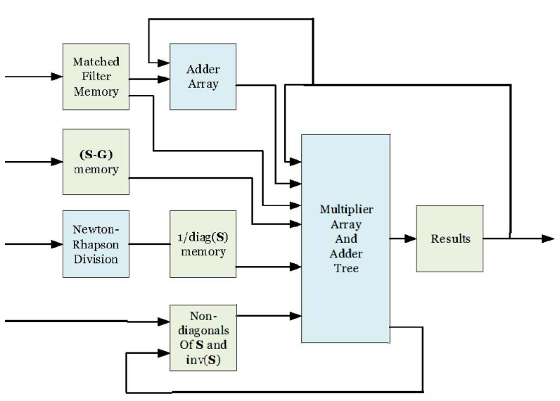
Figure 8. Architecture of Stair Matrix Based Gauss-Seidel Method [18].
6. Analysis
Each of the aforementioned signal detection methods has its own advantages and disadvantages, which will be specifically analyzed below.
The ADMM method decomposes large convex optimization problems into several smaller subproblems, solving these smaller subproblems to obtain the final result. It has the following characteristics: 1) It converges quickly when the number of base station antennas is close to the number of users. 2) It is relatively easy to implement and suitable for multi-signal processing tasks. 3) For non-convex optimization problems, it may converge to a local optimum rather than a global optimum. The NS expansion method reduces the complexity associated with directly inverting a matrix by converting the matrix inversion into solving a series expansion of the matrix. It has the following characteristics: 1) It lowers computational complexity by replacing direct matrix inversion with the first few terms of the matrix series. 2) The algorithm is relatively simple to implement and applicable to various circuits. 3) The convergence conditions are restrictive: the effectiveness of the NS expansion depends on the spectral radius of the matrix being less than 1. If this condition is not met, the series may not converge, thus affecting the method's applicability. Iterative methods approximate the true solution by continuously updating intermediate values. They have the following characteristics: 1) Accuracy can be improved by increasing the number of iterations, meeting the requirements of various signal detection environments. 2) Flexibility: iterative methods can adjust parameters such as the iterative expression, initial values, and step sizes based on different use cases, making them applicable to a wide range of scenarios. 3) Iterative methods require storing a large number of intermediate values, necessitating high computational resources and placing higher demands on the implementation circuit.
For signal detection, we believe that future improvements can be made by combining the Neumann series expansion with iterative methods. By using the first few terms of the NS as the initial values for the iterative method, we can ensure high performance while maintaining acceptable computational complexity, thereby achieving better system performance for signal detection.
7. Conclusion
In this paper, we classify and introduce three methods and their circuit structures used to reduce computational complexity in signal detection. We also discuss typical methods for lowering computational complexity during signal detection and identify suitable detection algorithms and their circuit architectures for different usage conditions. In future research, we can focus on integrating the NS expansion method with iterative methods. By setting the initial values for the iteration as the first few terms of the Neumann series expansion, we aim to reduce complexity and improve performance. Additionally, relevant simulations and validations will be conducted to verify the effectiveness of this approach.
References
[1]. Lee J, Han J K, Zhang J. MIMO technologies in 3GPP LTE and LTE-advanced[J]. EURASIP Journal on wireless communications and networking, 2009, 2009: 1-10.
[2]. Abdulhasan M Q, Salman M I, Ng C K, et al. Review of channel quality indicator estimation schemes for multi-user MIMO in 3GPP LTE/LTE-A systems[J]. KSII Transactions on Internet and Information Systems (TIIS), 2014, 8(6): 1848-1868.
[3]. Harkat H, Monteiro P, Gameiro A, et al. A survey on MIMO-OFDM systems: Review of recent trends[J]. Signals, 2022, 3(2): 359-395.
[4]. Raj T, Mishra R, Kumar P, et al. Advances in MIMO antenna design for 5G: A comprehensive review[J]. Sensors, 2023, 23(14): 6329.
[5]. Liu Shuai. Cooperative Localization Method Based on Maximum Likelihood Estimation in LTE Networks[J]. Microcomputer Applications, 2018, 34(7):3.
[6]. Jiang Xiaolin, Cui Jingyan, Zhang Guangzhou. Improved Spherical Signal Detection Algorithm for MIMO Systems[J]. Journal of Heilongjiang Institute of Science and Technology, 2018, 28(6): 706-711.
[7]. WANG Hongyan. Performance Analysis of Large-Scale MIMO Hybrid Relay Systems Based on Zero-Forcing Beamforming Techniques[J]. Modern Information Technology, 2023, 7(22): 57-62.
[8]. LÜ Chaoli, LUO Zhongqiang. V2X Channel Estimation Scheme Combining Improved Minimum Mean Square Error and Deep Learning[J]. Radio Communications Technology, 2024(6).
[9]. Shahabuddin S, Hautala I, Juntti M, et al. ADMM-based infinity-norm detection for massive MIMO: Algorithm and VLSI architecture[J]. IEEE Transactions on Very Large Scale Integration (VLSI) Systems, 2021, 29(4): 747-759.
[10]. Wu M, Yin B, Vosoughi A, et al. Approximate matrix inversion for high-throughput data detection in the large-scale MIMO uplink[C]//2013 IEEE international symposium on circuits and systems (ISCAS). IEEE, 2013: 2155-2158.
[11]. Wang F, Zhang C, Yang J, et al. Efficient matrix inversion architecture for linear detection in massive MIMO systems[C]//2015 IEEE International Conference on Digital Signal Processing (DSP). IEEE, 2015: 248-252.
[12]. Wu Z, Zhang C, Xue Y, et al. Efficient architecture for soft-output massive MIMO detection with Gauss-Seidel method[C]//2016 IEEE international symposium on circuits and systems (ISCAS). IEEE, 2016: 1886-1889.
[13]. Prabhu H, Edfors O, Rodrigues J, et al. Hardware efficient approximative matrix inversion for linear pre-coding in massive MIMO[C]//2014 IEEE International Symposium on Circuits and Systems (ISCAS). IEEE, 2014: 1700-1703.
[14]. Zhang C, Liang X, Wu Z, et al. On the low-complexity, hardware-friendly tridiagonal matrix inversion for correlated massive MIMO systems[J]. IEEE Transactions on Vehicular Technology, 2019, 68(7): 6272-6285.
[15]. Guo Y, Wang Z, Guan W, et al. A hardware-efficient massive MIMO detector using improved quasi-Newton method[J]. IEICE Electronics Express, 2023, 20(15): 20230281-20230281.
[16]. Zhang C, Wu Z, Studer C, et al. Efficient soft-output Gauss–Seidel data detector for massive MIMO systems[J]. IEEE Transactions on Circuits and Systems I: Regular Papers, 2018, 68(12): 5049-5060.
[17]. Kang B, Yoon J H, Park J. Low‐complexity massive MIMO detectors based on Richardson method[J]. Etri Journal, 2017, 39(3): 326-335.
[18]. Shahabuddin S, Albreem M A, Shahabuddin M S, et al. FPGA implementation of stair matrix based massive MIMO detection[C]//2021 IEEE 12th Latin America Symposium on Circuits and System (LASCAS). IEEE, 2021: 1-4.
[19]. Jeon C, Mirza G, Ghods R, et al. VLSI design of a nonparametric equalizer for massive MU-MIMO[C]//2017 51st Asilomar Conference on Signals, Systems, and Computers. IEEE, 2017: 1504-1508.
[20]. Boyd S , Parikh N , Chu E ,et al.Distributed Optimization and Statistical Learning via the Alternating Direction Method of Multipliers[J].Foundations & Trends in Machine Learning, 2010, 3(1):1-122.
[21]. Meinerzhagen P A , Rodrigues J N , Burg A P .Standard-Cell Based Memories (SCMs): from Sub-VT to Error-Resilient Systems[C]//2012.
[22]. Jin J , Zhang Z , You X ,et al.Massive MIMO Detection based on Barzilai-Borwein Algorithm[J].IEEE, 2018
Cite this article
Wang,C. (2024). Analyses for Signal Detection Algorithms and Corresponding VLSI Architectures Applied for Massive MIMO Systems. Applied and Computational Engineering,112,176-185.
Data availability
The datasets used and/or analyzed during the current study will be available from the authors upon reasonable request.
Disclaimer/Publisher's Note
The statements, opinions and data contained in all publications are solely those of the individual author(s) and contributor(s) and not of EWA Publishing and/or the editor(s). EWA Publishing and/or the editor(s) disclaim responsibility for any injury to people or property resulting from any ideas, methods, instructions or products referred to in the content.
About volume
Volume title: Proceedings of the 5th International Conference on Signal Processing and Machine Learning
© 2024 by the author(s). Licensee EWA Publishing, Oxford, UK. This article is an open access article distributed under the terms and
conditions of the Creative Commons Attribution (CC BY) license. Authors who
publish this series agree to the following terms:
1. Authors retain copyright and grant the series right of first publication with the work simultaneously licensed under a Creative Commons
Attribution License that allows others to share the work with an acknowledgment of the work's authorship and initial publication in this
series.
2. Authors are able to enter into separate, additional contractual arrangements for the non-exclusive distribution of the series's published
version of the work (e.g., post it to an institutional repository or publish it in a book), with an acknowledgment of its initial
publication in this series.
3. Authors are permitted and encouraged to post their work online (e.g., in institutional repositories or on their website) prior to and
during the submission process, as it can lead to productive exchanges, as well as earlier and greater citation of published work (See
Open access policy for details).
References
[1]. Lee J, Han J K, Zhang J. MIMO technologies in 3GPP LTE and LTE-advanced[J]. EURASIP Journal on wireless communications and networking, 2009, 2009: 1-10.
[2]. Abdulhasan M Q, Salman M I, Ng C K, et al. Review of channel quality indicator estimation schemes for multi-user MIMO in 3GPP LTE/LTE-A systems[J]. KSII Transactions on Internet and Information Systems (TIIS), 2014, 8(6): 1848-1868.
[3]. Harkat H, Monteiro P, Gameiro A, et al. A survey on MIMO-OFDM systems: Review of recent trends[J]. Signals, 2022, 3(2): 359-395.
[4]. Raj T, Mishra R, Kumar P, et al. Advances in MIMO antenna design for 5G: A comprehensive review[J]. Sensors, 2023, 23(14): 6329.
[5]. Liu Shuai. Cooperative Localization Method Based on Maximum Likelihood Estimation in LTE Networks[J]. Microcomputer Applications, 2018, 34(7):3.
[6]. Jiang Xiaolin, Cui Jingyan, Zhang Guangzhou. Improved Spherical Signal Detection Algorithm for MIMO Systems[J]. Journal of Heilongjiang Institute of Science and Technology, 2018, 28(6): 706-711.
[7]. WANG Hongyan. Performance Analysis of Large-Scale MIMO Hybrid Relay Systems Based on Zero-Forcing Beamforming Techniques[J]. Modern Information Technology, 2023, 7(22): 57-62.
[8]. LÜ Chaoli, LUO Zhongqiang. V2X Channel Estimation Scheme Combining Improved Minimum Mean Square Error and Deep Learning[J]. Radio Communications Technology, 2024(6).
[9]. Shahabuddin S, Hautala I, Juntti M, et al. ADMM-based infinity-norm detection for massive MIMO: Algorithm and VLSI architecture[J]. IEEE Transactions on Very Large Scale Integration (VLSI) Systems, 2021, 29(4): 747-759.
[10]. Wu M, Yin B, Vosoughi A, et al. Approximate matrix inversion for high-throughput data detection in the large-scale MIMO uplink[C]//2013 IEEE international symposium on circuits and systems (ISCAS). IEEE, 2013: 2155-2158.
[11]. Wang F, Zhang C, Yang J, et al. Efficient matrix inversion architecture for linear detection in massive MIMO systems[C]//2015 IEEE International Conference on Digital Signal Processing (DSP). IEEE, 2015: 248-252.
[12]. Wu Z, Zhang C, Xue Y, et al. Efficient architecture for soft-output massive MIMO detection with Gauss-Seidel method[C]//2016 IEEE international symposium on circuits and systems (ISCAS). IEEE, 2016: 1886-1889.
[13]. Prabhu H, Edfors O, Rodrigues J, et al. Hardware efficient approximative matrix inversion for linear pre-coding in massive MIMO[C]//2014 IEEE International Symposium on Circuits and Systems (ISCAS). IEEE, 2014: 1700-1703.
[14]. Zhang C, Liang X, Wu Z, et al. On the low-complexity, hardware-friendly tridiagonal matrix inversion for correlated massive MIMO systems[J]. IEEE Transactions on Vehicular Technology, 2019, 68(7): 6272-6285.
[15]. Guo Y, Wang Z, Guan W, et al. A hardware-efficient massive MIMO detector using improved quasi-Newton method[J]. IEICE Electronics Express, 2023, 20(15): 20230281-20230281.
[16]. Zhang C, Wu Z, Studer C, et al. Efficient soft-output Gauss–Seidel data detector for massive MIMO systems[J]. IEEE Transactions on Circuits and Systems I: Regular Papers, 2018, 68(12): 5049-5060.
[17]. Kang B, Yoon J H, Park J. Low‐complexity massive MIMO detectors based on Richardson method[J]. Etri Journal, 2017, 39(3): 326-335.
[18]. Shahabuddin S, Albreem M A, Shahabuddin M S, et al. FPGA implementation of stair matrix based massive MIMO detection[C]//2021 IEEE 12th Latin America Symposium on Circuits and System (LASCAS). IEEE, 2021: 1-4.
[19]. Jeon C, Mirza G, Ghods R, et al. VLSI design of a nonparametric equalizer for massive MU-MIMO[C]//2017 51st Asilomar Conference on Signals, Systems, and Computers. IEEE, 2017: 1504-1508.
[20]. Boyd S , Parikh N , Chu E ,et al.Distributed Optimization and Statistical Learning via the Alternating Direction Method of Multipliers[J].Foundations & Trends in Machine Learning, 2010, 3(1):1-122.
[21]. Meinerzhagen P A , Rodrigues J N , Burg A P .Standard-Cell Based Memories (SCMs): from Sub-VT to Error-Resilient Systems[C]//2012.
[22]. Jin J , Zhang Z , You X ,et al.Massive MIMO Detection based on Barzilai-Borwein Algorithm[J].IEEE, 2018