


1. Introduction
In light of the accelerated expansion of contemporary transportation infrastructure, particularly in China, the safety and durability of steel bridges, which serve as vital transportation conduits in vast numbers, have come under heightened scrutiny due to their extensive transportation networks. Steel bridges are susceptible to damage such as cracks and corrosion due to multiple factors including long-term exposure to traffic loads, environmental erosion, and material aging. If these damages are not detected and maintained in a timely manner, they may affect the stability of the bridge structure and pose a threat to public safety. Therefore, regular inspection and evaluation of steel bridges are of irreplaceable importance in ensuring their safe operation. However, traditional steel bridge inspection methods, such as manual climbing or using cable cars, have problems such as low efficiency, high cost, and high risk. In this context, bridge inspection robots have emerged with their unique advantages. The high-precision sensors and imaging systems they are equipped with can provide more accurate damage identification and assessment, greatly improving the accuracy and reliability of detection. In addition, the utilization of bridge inspection robots for inspection not only reduces operational risks, but also significantly reduces labor and time costs and improves the economy of inspection. In short, the implementation of this technology is anticipated to transform the domain of bridge inspection, thus providing more effective technical means to ensure the safe operation of bridges.
2. Related Work
Magnetic adsorption technology, a key attachment methods for wall climbing robots, is widely used in the maintenance of steel bridges and other metal structures. The Cooperative Climbing Robot Main Cable Version IV (CCRobot IV) was developed by Shenzhen Institute of Artificial Intelligence and Robotics (AIRS), as shown in Figure 1 [1]. The robot employes the handrail ropes on the maintenance walkway of suspension bridges as climbing supports, and operates with two sets of gripping boots, each equipped with four claws, which alternately open and close, simulating the stretching movements of worms to advance. During its “walk,” CCRobot IV carries multiple visual sensors on a lightweight composite frame, enabling comprehensive detection of main cables. And the Robug, a quadruped wall climbing robot based on magnetic adsorption technology for storage tanks in the nuclear industry, was developed by the City University of Hong Kong [2]. The robot uses suction cups on its feet to adhere to the wall, thereby enhancing its ability to transition between walls and ground, as shown in Figure 2. Compared with hexapod robots, performance is improved despite the simplified structure. However, quadruped robots are encumbered by a number of disadvantages, including a complex mechanical and control system, a slow motion speed, and low system stability.
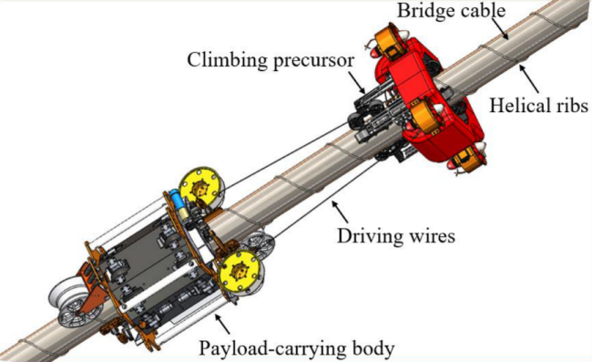
Figure 1. Overall design of CCRobot-IV.
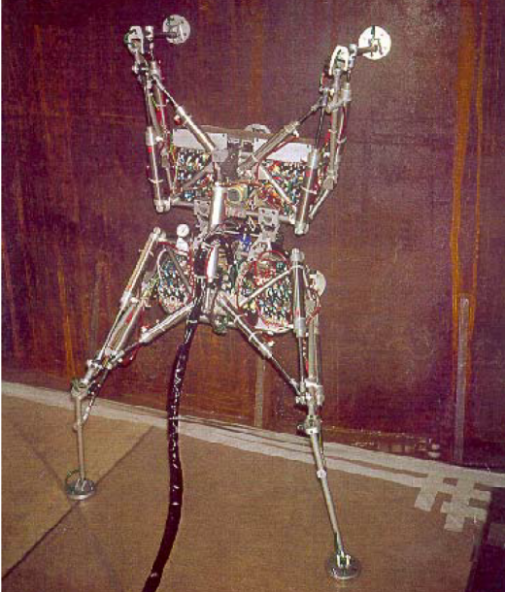
Figure 2. Robug Undergoing Automatic Floor-to-Wall Transfer
In recent years, negative pressure adhesion technology has emerged as an alternative to magnetic adhesion technology in wall climbing robots. The Harbin Institute of Technology has developed an advanced wheeled suspension magnetic adsorption device for ocean going vessels, which incorporates a robot motion mechanism with dual active wheel differential drive and dual driven wheel universal follow-up, allowing for flexible movement [3]. Permanent magnetic adsorption blocks installed around the driving wheels ensure that the robot remains securely attached to the steel wall. Similarly, Nanjing University of Science and Technology has also designed a wall climbing robot for bridge surface defect detection, as shown in Figure 3 [4]. This wall climbing robot uses a centrifugal pump to create a negative pressure environment and achieve the function of adsorption on the wall surface. To keep stable pressure inside the sealed chamber during the movement of the wall climbing robot, an adaptive control method is employed to dynamically adjust the centrifugal pump speed.
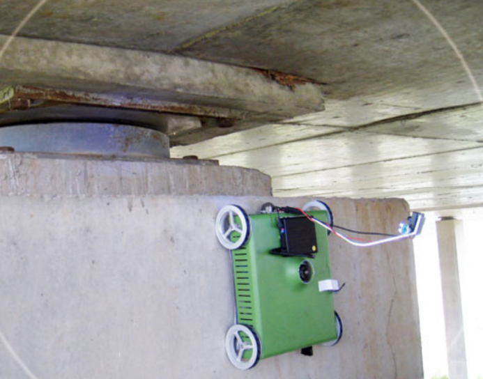
Figure 3. Schematic Diagram of a Wall Climbing Robot
Advances in technology have increasingly focused on integrating robotics with bridge inspection. Gifu University in Japan has developed a “Plesiosaur” bridge inspection robot [5]. This robot features a 20-meter-long robotic arm that extends from a truck positioned on the bridge, allowing for a detailed examination of the bridge’s internal structure. Besides, equipped with a camera mounted at the front of the robot, it provides real-time visuals displayed on a screen in the driver’s seat, facilitating detailed manual inspection and maintenance. Meanwhile, the University of Technology Sydney has developed an automated steel bridge maintenance system, as shown in Figure 4 [6]. This system is equipped with a range of non-destructive testing detectors and a navigation control system. The robot independently collects data around the bridge, maps the environment, and identifies areas requiring sandblasting. It then plans the nozzle paths and movement of the sandblasting platform to effectively clean the corroded areas, completing the bridge maintenance process.
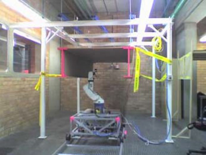
Figure 4. Prototype Mechanism of Bridge Inspection Robot
In addition, there are two main methods for assessing bridge safety. The first involves installing sensors on bridges, which can measure physical parameters such as temperature and displacement but cannot assess the condition of reinforcement and concrete surfaces. And the second method involves manual inspection or the use of advanced equipment. Missouri University of Technology in the U.S. has developed a robot bridge inspection system tusing unmanned aerial vehicles (UAVs) [7]. These drones are equipped with visible light cameras for 3D bridge modeling, infrared thermal imagers to detect internal defects, and LiDAR for creating detailed point cloud models. The visible light cameras provide model accuracy up to 2mm, infrared imagers reveal issues such as concrete delamination, and LiDAR helps locate defects precisely. Harbin Institute of Technology has innovated by incorporating large-scale models into bridge maintenance [8]. Their system combines data from various sensors and inspection robots to automatically assess bridge conditions, aiding in decision-making.
3. Methods and Materials
3.1. Overall Design
With the increasing scale and complexity of modern bridges, traditional bridge maintenance methods are no longer able to meet current needs. In order to address these issues, this study proposes a design of a novel magnetic adsorption robot aimed at improving the maintenance efficiency and safety of steel bridges. The proposed design takes into account the unique characteristics of bridge structures and the specific requirements for maintenance operations, including but not limited to enhancing the robot’s emergency protection measures in case of emergency, improving the robot’s ability to traverse obstacles, and fusing multi-sensors to realize intelligent and autonomous operation that autonomously scans all the areas without leaving any blind spots.
The magnetic adsorption robot designed in this study emulates the locomotion of caterpillars and is equipped with multiple sensors, enabling it to maneuver freely in all directions within steel structures and to autonomously retract upon completing inspections. Performance specifications for the magnetic adsorption robot have been established based on comprehensive field studies, as detailed in Table 1..
Table 1. Performance Specifications
Performance Specifications | Specification |
Wall Movement Speed | 11~15 m/ min |
Obstacle Crossing Height | 50 mm |
Body Weight | 30 Kg |
Load Capacity | 15 Kg |
Working Height | 0~100 m |
Working Function | Steel bridge inspection operations |
Adsorption Method | Magnetic adsorption method |
Control Method | Bluetooth for sequential control and ground remote control operation |
3.2. Mechanical Design and Analysis
Traditional wall climbing maintenance robots, whether using magnetic suction or negative pressure suction, have a common drawback, namely, weak obstacle crossing ability. The magnetic robot should not be too far away from the steel surface, otherwise the adsorption effect may disappear. Negative pressure adsorption requires the design of a vacuum pump, resulting in a relatively large volume and weight, which affects its obstacle-crossing ability. Inspired by the operation of the combination of large and small robotic arms on the Chinese space station, a dual robotic arm mechanism is designed [9]. Electromagnets are installed at the bases of the two mechanical arms, and the control of the electromagnets is achieved by turning on and off the electromagnetic wires. To discuss the kinematic state and operation of a dual robotic arm, the corresponding robotic model should first be modeled, which should include the position and attitude of a point in space. Multiple coordinate systems are required to establish the connections between the linkages of the robotic arm.
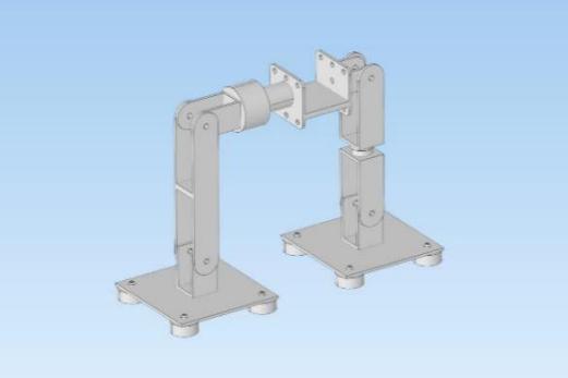
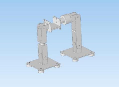
Figure 5. Structural Design Drawing
3.3. Kinematics
First, the poses of the linkage and end effector of the robotic arm are determined. Second, the bases of the two robotic arms are fixed and set as the base coordinate. Based on the connection between the linkage and joints of the robotic arm, propose many applicable kinematic modeling methods. The D-H matrix parameter method is used for modeling in the paper.
3.3.1. Kinematic Modeling. The D-H method is selected to set up the coordinate system of the dual robotic arms [10]. At the same time, in order to facilitate differentiation and analysis, the robotic arms are divided into a master robotic arm and a slave robotic arm. Due to the asymmetry of the two robotic arms, it is necessary to calculate the pose of each arm separately. However, since the algorithms are consistent, one of them is taken as an example for calculation here. The schematic diagram of the coordinate system is shown in Figure 6, from which Table 2 can be listed.
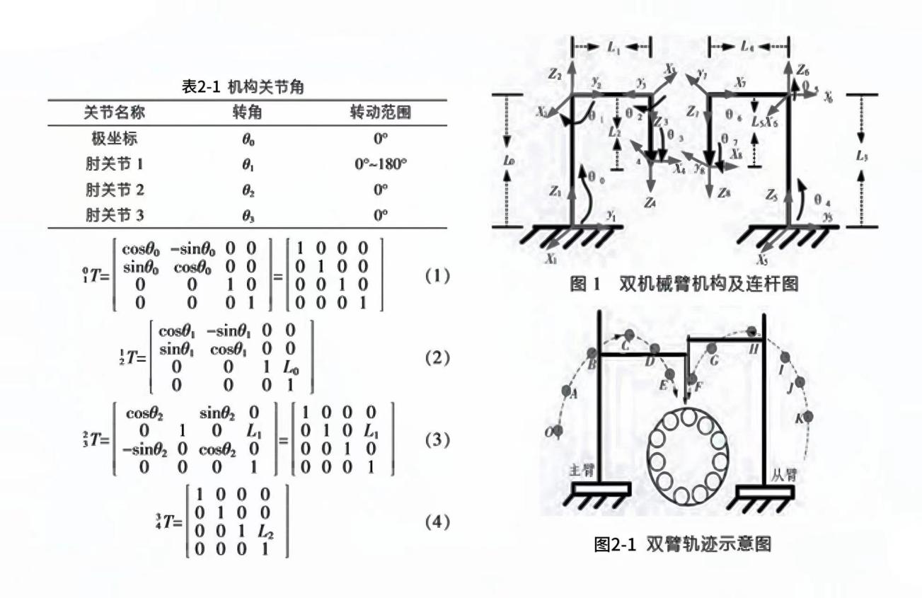
Figure 6. Coordinate Diagram of Dual Robotic Arm Mechanism
Table 2. Joint Angles of the Mechanism
Joint Name | Rotation Angle | Rotation Range |
Polar coordinates | \( {θ_{0}} \) | \( {0^{°}} \) |
Joint 1 | \( {θ_{1}} \) | \( {0^{°}}-{180^{°}} \) |
Joint 2 | \( {θ_{2}} \) | \( {0^{°}} \) |
Joint 3 | \( {θ_{3}} \) | \( {0^{°}} \) |
3.3.2. Kinematic Analysis. According to Figure 7 and Table 2, the pose matrix of each link of the main robotic arm can be represented as:
\( {_4^0}T=[\begin{matrix}cos{θ_{1}} & -sin{θ_{1}} & 0 & -{L_{1}}sin{θ_{1}} \\ sin{θ_{1}} & cos{θ_{1}} & 0 & {L_{1}}cos{θ_{1}} \\ 0 & 0 & 1 & {L_{2}}+{L_{0}} \\ 0 & 0 & 0 & 1 \\ \end{matrix}] \) (1)
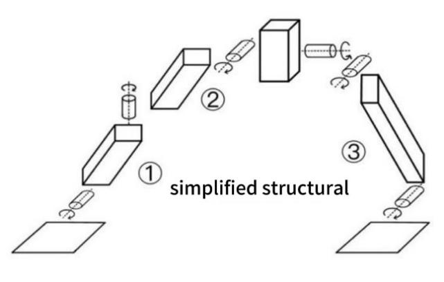
Figure 7. Simplified Structural Diagram
The motion equation of the terminal point of the main robotic arm is: \( {_4^0}T \) = \( {_1^0}T∙{_2^1}T∙{_3^2}T∙{_4^3}T=[\begin{matrix}R & P \\ 0 & I \\ \end{matrix}] \) , From this, it can be seen that the D-H matrix consists of four parts: R-rotation matrix, P-position matrix, O-perspective matrix, and I-ratio matrix. the lengths of the three links of the robot (①, ②, and ③ ) are 12 cm, 12 cm, and 28 cm, respectively, the number of joints is 3, and the rotational range is 0° ~ 270°. Substituting the values in Table 1 and the relevant parameters gives::
\( {_4^0}T=[\begin{matrix}1 & 0 & 0 & 0 \\ 0 & 1 & 0 & 20 \\ 0 & 0 & 1 & 45 \\ 0 & 0 & 0 & 1 \\ \end{matrix}] \) (2)
In the design of a robotic arm, the initial position of the arm is known, and in order for the arm to reach the desired position, it is necessary to know the values of the joints that need to be moved in order to reach the specified position, and the values of the joint angles are calculated according to the inverse kinematics equations. Firstly, since \( {_4^0}T={_1^0}T{_2^1}T{_3^2}T{_4^3}T \) , i.e. \( {({_1^0}T)^{-1}}({_4^0}T)={_2^1}T{_3^2}T{_4^3}T \) , the angle of \( {θ_{1}} \) can be found. Secondly, since \( ({{_2^1}T)^{-1}}({{_1^0}T)^{-1}}({_4^0}T)={_3^2}T{_4^3}T \) , other joint poses and angles can be found.
3.4. Adsorption Method
According to the classification of adsorption functions, there are three common adsorption methods for wall climbing robots, which are vacuum adsorption, magnetic adsorption, and thrust adsorption [11]. Vacuum adsorption, facilitated by a vacuum pump generating negative air pressure within the suction cup chamber, allows wall-climbing robots to adhere effectively to vertical surfaces. Based on the configuration of suction cups, vacuum adsorption mechanisms can be categorized into single and multi-suction cup systems. A key advantage of vacuum adsorption is its versatility across various wall materials. However, it demands a smooth and clean surface, as unevenness or debris may compromise the suction, leading to air leakage and loss of adhesion. Magnetic adsorption, on the other hand, can be implemented via electromagnetic or permanent magnet systems. Electromagnetic adsorption, which requires a continuous power supply to maintain magnetic force, offers superior control over the adhesion process. In contrast, permanent magnet adsorption is independent of power supply, offering high reliability, albeit with reduced control flexibility. Magnetic adsorption typically provides stronger adhesion and greater adaptability to different wall surfaces compared to vacuum adsorption, though it is limited to magnetic materials. Thrust adsorption employs propellers or ducted fans to generate a continuous thrust towards the wall, thereby enabling the robot to maintain stable contact with the surface. This method allows the robot to more easily navigate obstacles due to the constant application of force.
Due to the decision to use a dual-arm structure and the working environment being a steel bridge, electromagnetic adsorption was ultimately selected as the most feasible option, considering both control complexity and cost. Since electromagnets require a significant amount of current, relying solely on the Arduino board for power supply is insufficient; the voltage provided cannot enable the electromagnets to reach their rated power, and the required current exceeds the board’s pin current limit, potentially damaging the board. Therefore, a separate DC power supply was chosen to power the electromagnets.
3.5. Robot Control System
3.5.1. Communication System Design. The Arduino Uno is chosen due to its relatively low cost, extensive libraries, and example codes, along with a large community providing support and online resources that help resolve issues encountered during the development process. For robotic arms, the Arduino Uno offers sufficient input/output ports, analog inputs, and PWM outputs, which meet basic control requirements. Although the Arduino Uno is a foundational model, it is compatible with various expansion boards and sensors, allowing for functional enhancements through additional modules, such as motor driver boards and servo control boards, to accommodate different needs. Among the options of infrared remote control, microcontroller-based control, and Bluetooth control, Bluetooth control is selected after careful consideration. Infrared remote control tends to encounter signal reception issues, and microcontroller programming is overly complex with limited operational modes. Bluetooth control ensures accurate signal reception while enabling a broader range of operations. The HC-05 Bluetooth module is selected for this purpose. The HC-05 is a high-performance, dual-mode Bluetooth serial communication module that supports a wide range of baud rates from 4800 to 1382400 and is compatible with both 5V and 3.3V microcontroller systems. It is user-friendly, offers flexible connectivity, and provides a high cost-performance ratio. Additionally, as an industrial-grade product, the HC-05 delivers stable performance and high reliability.
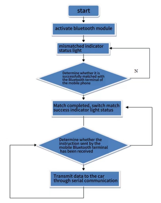
Figure 8. System Bluetooth Communication Subroutine Flow Chart
3.5.2. Motion System Design. The process of servo motor control involves the following steps: First, connect each servo's control wire to the digital I/O pins of the Arduino Uno, ensuring that the six PWM pins are used. Additionally, make sure the servo's power wire is connected to an appropriate power source, and the ground wire is connected to the Arduino's GND. Since servos typically require a larger current, it is recommended to use an external power supply instead of powering them through the Arduino, and ensure that the negative terminal of the external power supply is connected to the Arduino's GND. To simplify servo control, the Arduino Servo library can be used, as it provides functions for easily setting the servo's angle. In the program, define six servo objects and assign a digital pin to each servo. In the setup() function, use the attach() function to associate each servo object with the specified pin. In the loop() function, use the write() function to set the angle of each servo, and write control logic to achieve different motion modes, such as rotation and swinging.
4. Experimental Results and Analysis
4.1. Servo Motor Performance Analysis
In the performance testing of the servo motors, a notable deviation was observed in the performance of the main load-bearing servo motors. Compared to other servo motors, these deviations were notably larger, with specific test results shown in Table 3. Deviations in other servo motors ranged from 1 \( ° \) and 2 \( ° \) , which can be ignored, as. This substantial deviation underscores the need for further optimization of the stability and accuracy of the main load-bearing servo motors. To ensure that the robot operates stably under various loads and environmental conditions, a thorough investigation and adjustment of this issue are necessary to enhance the overall system performance.
Table 3. Performance Testing of the Servo Motors
Servo Number | Set rotation ( \( ° \) ) | Actual rotation ( \( ° \) ) | Deflection ( \( ° \) ) |
1 | 90 | 95 | 5 |
2 | 90 | 96 | 6 |
2 | 90 | 83 | -7 |
3 | 90 | 86 | -4 |
4 | 90 | 93 | 3 |
5 | 90 | 95 | 5 |
4.2. Robot Deployment
Through practical performance testing, the magnetic adhesion robot has demonstrated satisfactory performance on steel structures. The experimental results show that the robot can consistently adhere to the steel surface and exhibit excellent obstacle-crossing capabilities. During the tests, the robot successfully overcame various protrusions and depressions and was able to move freely within the steel structure. In actual operations, the robot effectively performed inspection and maintenance tasks, proving the effectiveness and practicality of its design. These test results indicate that the application of the magnetic adhesion robot in steel bridge maintenance not only improves maintenance efficiency but also enhances operational safety and reliability. The animation demonstration is shown in the link in the appendix.
4.3. Performance Summarization
Although significant progress has been made in wall-climbing robot technology in recent years, some limitations still exist. The magnetic adhesion robot designed in this study combines the advantages of traditional magnetic adhesion robots and vacuum adhesion robots, thus providing higher stability and flexibility. This integrated design has demonstrated excellent performance in practical applications, highlighting the potential and effectiveness of the technology for steel structure maintenance. Future research will focus on several key areas. First, efforts will be directed toward optimizing the design of the electromagnets to reduce their weight and enhance their performance. Second, improvements will be made to the torque capacity of the servo motors to increase the robot's load-bearing capability. Additionally, further advancements in the robot's automation and intelligence will be pursued, including optimizing circuit design and enhancing the adaptability of the magnetic adhesion system. Improvements will also be made to the robot's obstacle-crossing ability and mobility to better handle more complex maintenance environments. These enhancements will advance magnetic adhesion robot technology, providing more efficient and reliable solutions for maintenance tasks across various industries.
5. Conclusion
The current technological stage of magnetic robots presents significant challenges to achieving full automation, primarily due to the reliance on remote control and semi-automated systems, and the need to balance the weight of electromagnets with the torque capacity of servo systems. These limitations not only restrict the effectiveness and efficiency of maintenance operations, but constrain the robot’s adaptability to a variety of work environments. Addressing the issues of excessive electromagnet weight and insufficient torque capacity of servos can be partly managed by employing a direct current power supply. However, this approach introduces a dependence on external power sources, which in turn limits the portability and operational range of the robots. Therefore, future development efforts must prioritize optimizing electromagnet design to reduce weight and enhancing servo performance to increase torque capacity. In the next development plan, emphasis will be placed on increasing the level of automation and intelligence, optimizing the circuit design and reducing its size, thus enhancing the adaptability of the magnetic adsorption system, as well as boosting the obstacle-crossing and mobility capabilities.
Appendix
The robot crossing animation can be viewed at: https://github.com/EvenIshtar/A-Magnetic-Climbing-Robot
References
[1]. Zheng, Z., Zhang, W., Fu, X., Hazken, S., Hu, X., Chen, H., Luo, J. and Ding, N. (2022) Ccrobot-iv: an obstacle-free split-type quad-ducted propeller-driven bridge stay cable-climbing robot. IEEE Robotics and Automation Letters, 7(4): 11751-11758.
[2]. Luk, B.L., Cooke, D.S., Galt, S., Collie, A.A. and Chen, S. (2005). Intelligent legged climbing service robot for remote maintenance applications in hazardous environments. Robotics and Autonomous Systems, 53(2): 142-152.
[3]. Dai, Q. (2014) Research on Wall-Climbing Robot for Bridge Inspection and Its Adaptive Control Technique. Nanjing University of Science and Technology.
[4]. Zhang, X. A Study of a Wheeled Suspended Magnetically Adsorbed Wall-Climbing Robot. Harbin Institute of Technology.
[5]. Gifu University SIP (2020) Periodic inspection of PC bridge with both robot technologies and close visual observation. http://me-unit.net/wp-content/uploads/2020/05/ConMat20-rokugo-20200204-v4.pdf
[6]. Liu, D., et al. (2008) A robotic system for steel bridge maintenance : research challenges and system design. IEEE International Conference on Robotics and Automation.
[7]. Karim, M.M., Dagli, C.H. and Qin, R. (2020) Modeling and simulation of a robotic bridge inspection system. Procedia Computer Science, 168: 177-185.
[8]. Chen, X., et al. (2024) Revolutionizing Bridge Operation and maintenance with LLM-based Agents: An Overview of Applications and Insights.
[9]. Li, C., Jiang, Z., Li, Z., Fan, C. and Liu, H. (2019) A Novel Semi-Autonomous Teleoperation Method for the TianGong-2 Manipulator System. in IEEE Access, 7: 164453-164467.
[10]. Wu, L., et al. (2019) Geometric interpretation of the general POE model for a serial-link robot via conversion into D-H parameterization. 2019 International Conference on Robotics and Automation (ICRA), Montreal, QC, Canada, 7360-7366.
[11]. La, H.M., et al. (2019) Automated robotic monitoring and inspection of steel structures and bridges. Robotica, 37(5): 947–967.
Cite this article
Zhou,S. (2024). A Magnetic Climbing Robot for Steel Bridge Inspection. Applied and Computational Engineering,81,171-180.
Data availability
The datasets used and/or analyzed during the current study will be available from the authors upon reasonable request.
Disclaimer/Publisher's Note
The statements, opinions and data contained in all publications are solely those of the individual author(s) and contributor(s) and not of EWA Publishing and/or the editor(s). EWA Publishing and/or the editor(s) disclaim responsibility for any injury to people or property resulting from any ideas, methods, instructions or products referred to in the content.
About volume
Volume title: Proceedings of the 2nd International Conference on Machine Learning and Automation
© 2024 by the author(s). Licensee EWA Publishing, Oxford, UK. This article is an open access article distributed under the terms and
conditions of the Creative Commons Attribution (CC BY) license. Authors who
publish this series agree to the following terms:
1. Authors retain copyright and grant the series right of first publication with the work simultaneously licensed under a Creative Commons
Attribution License that allows others to share the work with an acknowledgment of the work's authorship and initial publication in this
series.
2. Authors are able to enter into separate, additional contractual arrangements for the non-exclusive distribution of the series's published
version of the work (e.g., post it to an institutional repository or publish it in a book), with an acknowledgment of its initial
publication in this series.
3. Authors are permitted and encouraged to post their work online (e.g., in institutional repositories or on their website) prior to and
during the submission process, as it can lead to productive exchanges, as well as earlier and greater citation of published work (See
Open access policy for details).
References
[1]. Zheng, Z., Zhang, W., Fu, X., Hazken, S., Hu, X., Chen, H., Luo, J. and Ding, N. (2022) Ccrobot-iv: an obstacle-free split-type quad-ducted propeller-driven bridge stay cable-climbing robot. IEEE Robotics and Automation Letters, 7(4): 11751-11758.
[2]. Luk, B.L., Cooke, D.S., Galt, S., Collie, A.A. and Chen, S. (2005). Intelligent legged climbing service robot for remote maintenance applications in hazardous environments. Robotics and Autonomous Systems, 53(2): 142-152.
[3]. Dai, Q. (2014) Research on Wall-Climbing Robot for Bridge Inspection and Its Adaptive Control Technique. Nanjing University of Science and Technology.
[4]. Zhang, X. A Study of a Wheeled Suspended Magnetically Adsorbed Wall-Climbing Robot. Harbin Institute of Technology.
[5]. Gifu University SIP (2020) Periodic inspection of PC bridge with both robot technologies and close visual observation. http://me-unit.net/wp-content/uploads/2020/05/ConMat20-rokugo-20200204-v4.pdf
[6]. Liu, D., et al. (2008) A robotic system for steel bridge maintenance : research challenges and system design. IEEE International Conference on Robotics and Automation.
[7]. Karim, M.M., Dagli, C.H. and Qin, R. (2020) Modeling and simulation of a robotic bridge inspection system. Procedia Computer Science, 168: 177-185.
[8]. Chen, X., et al. (2024) Revolutionizing Bridge Operation and maintenance with LLM-based Agents: An Overview of Applications and Insights.
[9]. Li, C., Jiang, Z., Li, Z., Fan, C. and Liu, H. (2019) A Novel Semi-Autonomous Teleoperation Method for the TianGong-2 Manipulator System. in IEEE Access, 7: 164453-164467.
[10]. Wu, L., et al. (2019) Geometric interpretation of the general POE model for a serial-link robot via conversion into D-H parameterization. 2019 International Conference on Robotics and Automation (ICRA), Montreal, QC, Canada, 7360-7366.
[11]. La, H.M., et al. (2019) Automated robotic monitoring and inspection of steel structures and bridges. Robotica, 37(5): 947–967.