


1. Introduction
The deterioration of the global environment, the depletion of fossil fuels, and so on are threats to the Earth's ecosystem and the development strategies of various nations. The implementation of sustainable development strategies and the reduction of energy consumption have become a global consensus [1]. In the industry, pursuing more efficient and energy-saving electronic devices has become a key objective of our century. As information technology develops, digital circuit design has expanded across various industries, particularly in communication, computing, automation control, and embedded systems. Counters, one of the indispensable and common circuit components in digital circuit design [2], perform counting operations based on pulse signals, frequency division, timing, control sequences, implementing registers, and so on. They are widely used in applications such as electronic clocks, delay circuits, DSPs, and automated control systems [3], playing an important role in modern electronic devices and communication systems. The design and optimization of counters directly impact the overall performance of these systems. With increasing demands for precision, speed, and power efficiency in modern digital systems, engineers need to explore more efficient counter-design methods. In this background, synchronous and asynchronous counters, as two main types of counters, have become key research topics in both academia and engineering, especially in their working principles, performance differences, and suitability for different applications.
The main difference between synchronous and asynchronous counters is the operation of their flip-flops’ toggle [4]. In asynchronous counters, flip-flops work in a cascading mode, with each stage driven by the output of the previous one. This structure is simple and has lower power consumption, but the signal cumulates delay across stages, limiting its performance in high-speed applications. Due to its low hardware resource usage, asynchronous counters are still widely used in low-frequency and simple systems. In synchronous counters, all flip-flops are driven by the same clock signal, ensuring that the state of each bit changes synchronously. This provides the counter with high stability and precision, making it widely applicable in high-speed systems with stringent accuracy requirements [5]. Therefore, a complete exploration of two types of counters can help engineers make informed design choices in different applications, optimizing the overall system performance. This paper uses the advantages of Logisim and Multisim, loss cost, and saving time, to achieve the circuit.[6]
The first chapter is the introduction, which first presents the research background and significance of the paper. The second chapter discusses the asynchronous MOD-60 counter designed in this paper. It involves the design of a MOD-60 counter with a single output, and a counter with two outputs by MOD-6*MOD-10. The circuit was simulated using Multisim and Logisim, and the results were obtained. The third chapter introduces the synchronous counter, which effectively solves the high delay issue of asynchronous counters, but results in higher power consumption. The last chapter is the conclusion, which summarizes this paper, comparing the advantages and disadvantages of synchronous and asynchronous counters. It also mentions each application and potential optimization scheme for future improvements.
2. Asynchronous counters
This section mainly illustrates the principle of the MOD60 counter. The design will be made of JK flip-flops. The counter performs addition counting, the principle is carrying from the lower bit to the higher bit one by one. Therefore, the flip-flops in the counter do not toggle synchronously [7]. It should change to 0 when 1 is added, and simultaneously send a carry signal to the higher bit to make it toggle.
2.1. Principle of MOD60 synchronous counter
To build a MOD 60 counter, the MOD 2n needs to be represented by an appropriate counter. Because the counter only could show the representation of MOD 2n, the counter only counts from 0 to 59[8]. So, the program needs to be stopped when the parts don’t need it according to the truth table formed by the representation of binary numbers. The truth table should be trimmed at 59.
A typical method to build a counter circuit is to use multiple JK flip-flops to complete. For one JK flip-flop component, when the input is a clock signal, the output will flip, which means that the change of output will be based on the change of clock signal, also for the next JK flip-flops, the change of output will be based on the change of last JK flip-flop. That is the reason why the counter doesn’t toggle synchronously.
The JK flip-flop represents the two binary numbers: 0 and 1. Building MOD 2n counter means n flip-flop is required. So, for the MOD 60 design, at least 6 JK flip-flops are required.
\( {2^{5}}=32 \lt 60\ \ \ (1) \)
\( {2^{6}}=64 \gt 60\ \ \ (2) \)
The counting range of a counter composed of 6 JK flip-flops exceeds 60, so it needs to follow the construction of the truncated sequence. The numbers of 0-59 are the numbers we need while the number 60-63 should be removed. In other words, when the counting process comes to number 60, the whole circuit should reset and begin at number 0. Thurs a unique characteristic by creating a truth table to analyze. By the characteristic of 111100(representing 60)-111111(representing 63), the condition could be found that the MSB to the fourth bit all represent 1. So, a NAND gate could be applied, the input is from the most significant bit (MSB) to the fourth bit, output is connected to the CLEAR. When the condition is met (the MSB to the fourth bit all represent 1), the output of NAND gates will be logic 0, telling the circuit it’s time to reset.
2.2. Multisim and Result
In Logisim, the design comes true by negative edge-triggered JK flip-flops. With the input clock signal turned on, the counter begins to count from 000000 to 110111, which are the binary expressions of 0 to 59. And the circuit has met the expectations. Follow the figure 1, when the counter jumps to 59. It will jump directly from 110111(the binary representation of 59) to 000000(the binary representation of 0), not continue to count the 111100(the binary representation of 60).
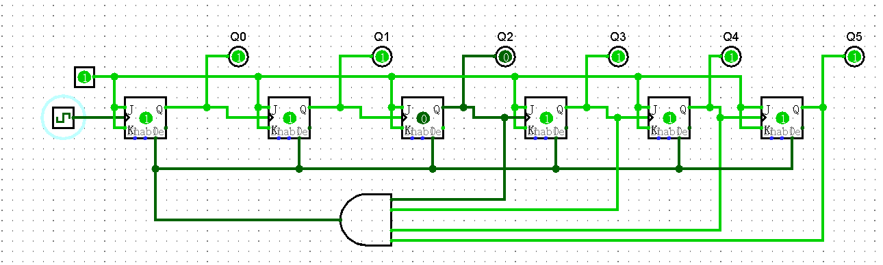
(a)
(b)
Figure 1: diagram of the synchronous counter (a)counts is 59 (b)counter reset
According to the diagram of the synchronous counter, achieving the circuit in Multisim. J is connected to the complement of output(Q´), and K is connected to the output(Q), that is J=Q´, K=Q. That means when Q=0, J=1, K=0, flip-flop is set on edge. When Q=1, J=0, K=1, flip-flop is reset on edge. And for the construction of the truncated sequence, it is different from the Logisim. The clear port (CLR) is always positive, when a negative signal enters it, it will clear the JK flip-flop. The Figure 2 is the simulation circuit in Multisim.
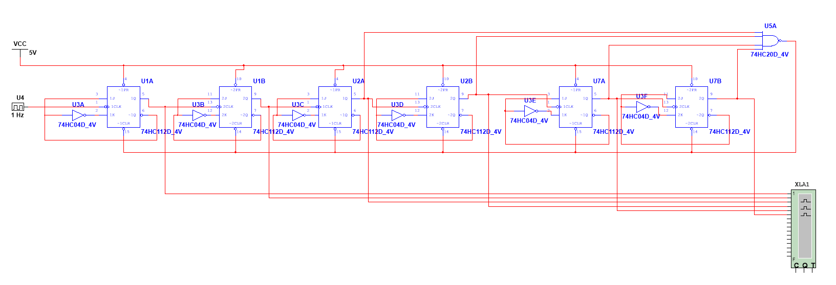
Figure 2: The simulation asynchronous circuit of MOD60 counter in Multisim.
The timing diagram is a graph of digital waveforms, showing the actual time relationship of waveforms and how each waveform changes from the others. From the timing diagram, it is easy to analyze the waveforms of the circuit. In Figure 3, the cyan line indicates the counter reaches 59s, and the yellow line indicates the counter reaches 60s. The binary representation of the cyan line is 110111. After one more second, all flip-flops are cleared, and the binary count resets to zero.
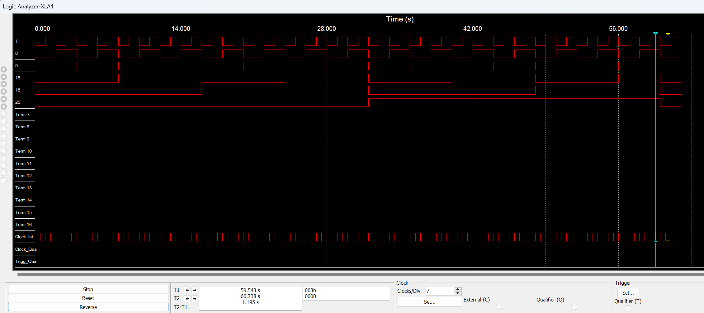
Figure 3: The timing diagram of the MOD60 circuit
Based on the Multisim limitation, the digital HEX display is 4-input, and the single number showing, which means that it could only support the input of 0000-1001(the range of 0 to 9). So, the design needs to be optimized. Based on the experiment and analysis above, the design of the MOD60 counter by applying JK flip-flops is flexible. In the limitation of Multisim, the design is optimized to be two parts. One part is to count the single digital number, the other part is to count the tens digital number.
Based on the experiment of the above design, increasing or decreasing several components in a series can expand or reduce the range of counting directly. So, the single digital number part uses 4 JK flip-flops, and the tens digital number part needs 3 JK flip-flops. And also follows the construction of the truncated sequence, stopping the single digital number part when it is 1001(the representation of 9) to become 0000(the representation of 0), and the RESET of the single digital number as a set input signal to tens digital number part. The tens digital number part is stopped at 101(the representation of 5). The design is optimized from MOD60 to MOD 6*MOD10, in other words, it is known as the decimal. In the Figure 4, it is the designed circuit. The bottom of the picture is the single digital number part, and the other is the tens digital number part.
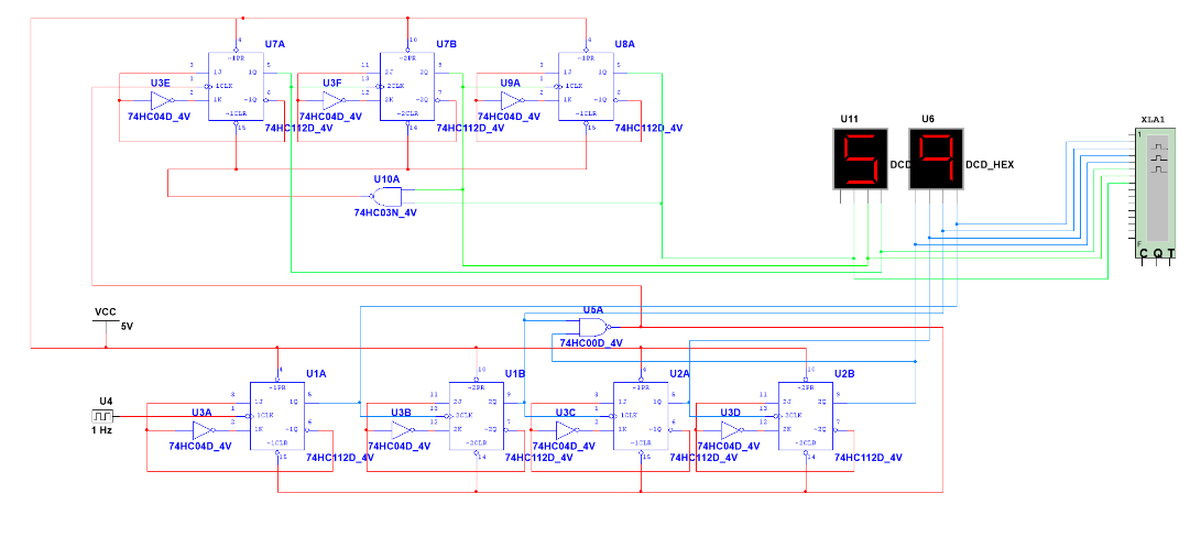
Figure 4: The simulation asynchronous circuit of MOD6*MOD10 counter in Multisim.
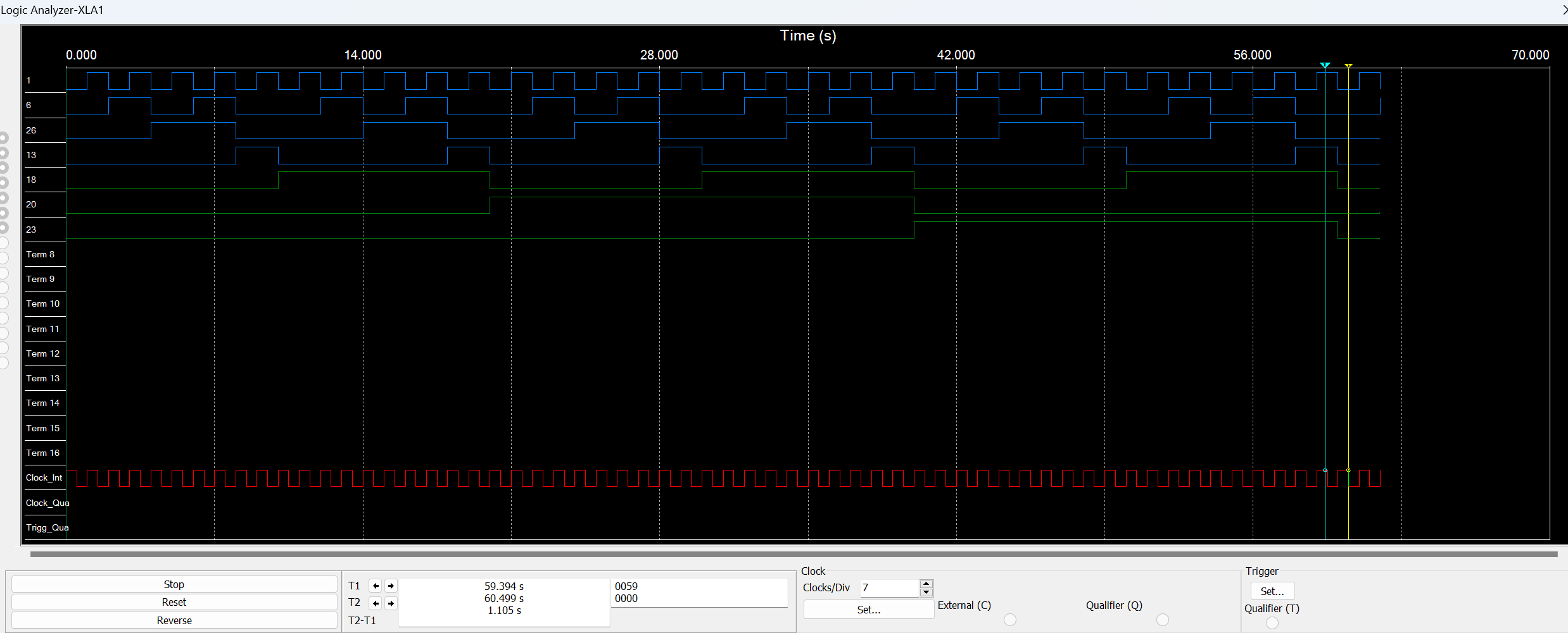
In Figure 5, the topmost waveform represents the LSB (Q0), and the bottommost waveform represents the HSB (Q7). The four blue waveforms represent MOD 10. The three green waveforms represent MOD 6. The cyan line T1 indicates the count has reached 5 and 9 (101 and 1001) when the time reaches 59s, and the yellow line T2 indicates the counter is reset (000 and 0000) when the time reaches 60s.
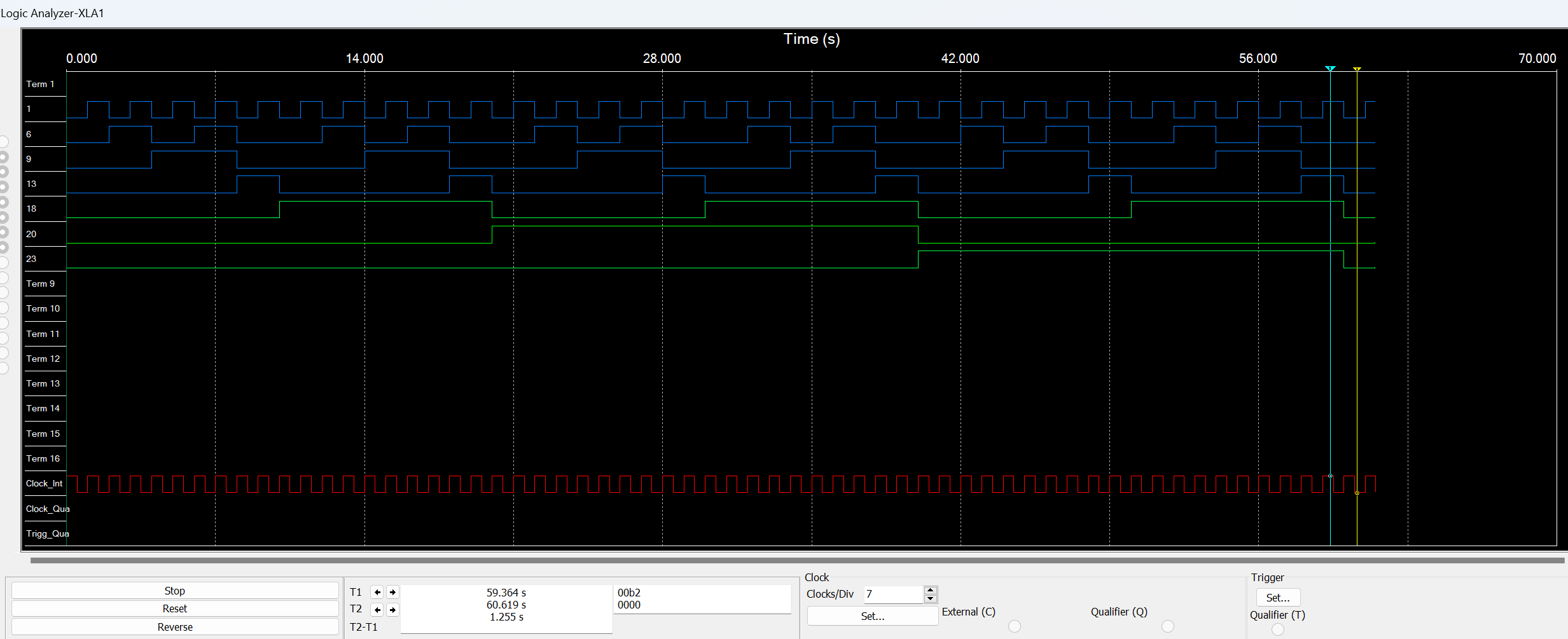
Figure 5: The timing diagram of the MOD6*MOD10 asynchronous circuit
Furthermore, there are some disadvantages of the circuit that should be considered. The typical asynchronous circuit design has a time delay exists [9]. And it could be larger when adding more JK flip-flops or counting more numbers [10]. In addition, the time delay will limit the clock frequency since the error will occur if the clock frequency is faster than the total time delay for one cycle. Taking a 4-bit counter as an example, in the eight cycles of the input clock, as the number of flip-flops on the longest path increases, the delay of the path gets higher and higher, as shown in Figure 6, the delay τ3 of Q3 is much greater than the delay τ0 of Q0. So, when the delay exceeds the input clock cycle, it will lead to the failure of the design and the circuit cannot be used, which is the fatal disadvantage of the asynchronous counter.
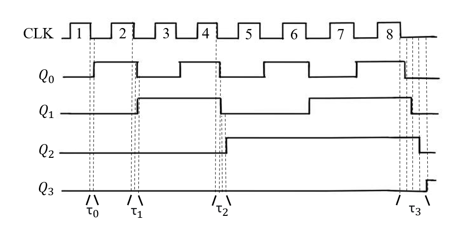
Figure 6: The delay of the 4-bit counter
3. Synchronous counter
The synchronous circuit means all JK flip-flops are controlled by the same clock signal, and all flip-flops toggle at the same time[4]. Compared to asynchronous counters, it does not have transient states and belongs to synchronous preset counting. [11] Rather than an asynchronous circuit, it offers higher precision and fast speed. It is based on the principle of binary addition [12], if much digital of a binary number is 1, the numbers below I digital are all 1, and the I digital needs to be toggled. Based on the principle, the AND gates are added in front of the JK flip-flops to control the JK flip-flops. The input of the AND gate is all outputs of JK flip-flops before the AND gate, output is the J and K. The driving equation of each JK flip-flop can be written.
\( {T_{0}}=1\ \ \ (3) \)
\( {T_{1}}={Q_{0}}\ \ \ (4) \)
\( {T_{2}}={Q_{0}}{Q_{1}}\ \ \ (5) \)
\( {T_{3}}={Q_{0}}{Q_{1}}{Q_{2}}\ \ \ (6) \)
\( {T_{4}}={Q_{0}}{Q_{1}}{Q_{2}}{Q_{3}}\ \ \ (7) \)
\( {T_{5}}={Q_{0}}{Q_{1}}{Q_{2}}{Q_{3}}{Q_{4}}\ \ \ (8) \)
the state equation of the circuit Also can be written.
\( Q_{0}^{*}=Q_{0}^{ \prime }\ \ \ (9) \)
\( Q_{1}^{*}={Q_{0}}Q_{1}^{ \prime }+Q_{0}^{ \prime }{Q_{1}}\ \ \ (10) \)
\( Q_{2}^{*}={Q_{0}}{Q_{1}}Q_{2}^{ \prime }+{({Q_{0}}{Q_{1}})^{ \prime }}{Q_{2}}\ \ \ (11) \)
\( Q_{3}^{*}={Q_{0}}{Q_{1}}{Q_{2}}Q_{3}^{ \prime }+{({Q_{0}}{Q_{1}}{Q_{2}})^{ \prime }}{Q_{3}}\ \ \ (12) \)
\( Q_{4}^{*}={Q_{0}}{Q_{1}}{Q_{2}}{Q_{3}}Q_{4}^{ \prime }+{({Q_{0}}{Q_{1}}{Q_{2}}{Q_{3}})^{ \prime }}{Q_{4}}\ \ \ (13) \)
\( Q_{5}^{*}={Q_{0}}{Q_{1}}{Q_{2}}{Q_{3}}{Q_{4}}Q_{5}^{ \prime }+{({Q_{0}}{Q_{1}}{Q_{2}}{Q_{3}}{Q_{4}})^{ \prime }}{Q_{5}}\ \ \ (14) \)
The final output equation is:
\( C={Q_{0}}{Q_{1}}{Q_{2}}{Q_{3}}{Q_{4}}{Q_{5}}\ \ \ (15) \)
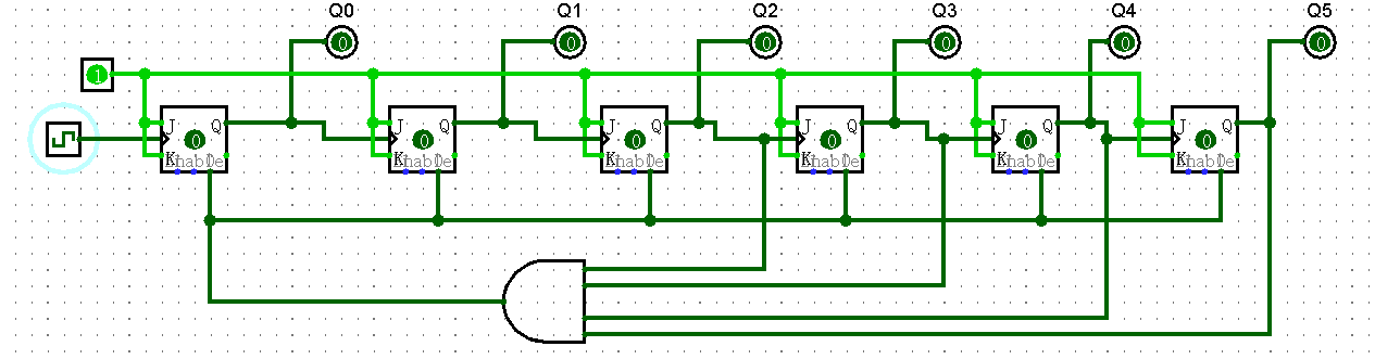
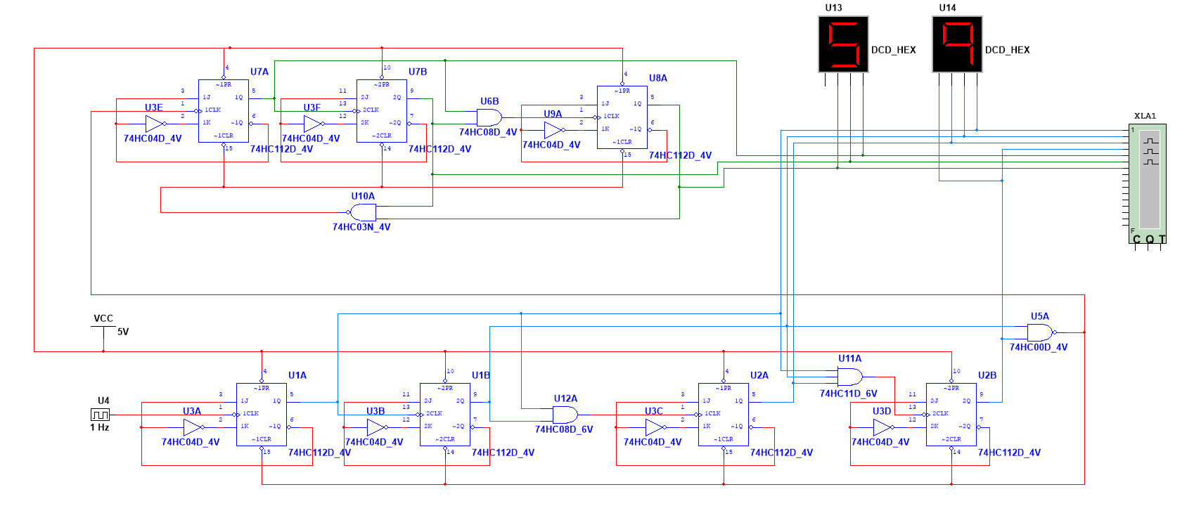
The circuit also needs to design and construct the truncated sequence. It is the same as the asynchronous circuit. By all conditions of the above mentioned, the synchronous circuit design is finished. Figure 7 is the schematic diagram by Logisim.

Figure 7: Diagram of the synchronous counter
Then optimizing the circuit similar to the asynchronous counter based on the schematic diagram. Using two digital HEX displays to show the counted numbers and separate the circuit into two parts. Figure 8(a) is the circuit simulated by Multisim. From Figure 8(b), it is clear that the circuit can complete the expected function and count normally to meet the expected requirements.
(a)
(b)
Figure 8: Synchronous counter (a)simulation in Multisim. (b)The timing diagram
4. Conclusion
Through the analysis and comparison of synchronous and asynchronous counters, the following conclusions can be drawn. First, asynchronous counters have a simple structure, are easy to design, and have low power consumption, making them suitable for low-frequency and power-sensitive application scenarios. However, as the number of counting bits increases, the delay issue in asynchronous counters becomes more pronounced, making them inadequate for high-frequency, high-precision applications. Therefore, asynchronous counters are more suitable for simple counting operations or systems where timing precision is not critical, such as basic event counting and low-frequency timers [8]. Although the design of asynchronous counters is relatively simple, their delay issues may limit their use in certain applications.
Synchronous counters, on the other hand, have all flip-flops driven simultaneously by the same clock, providing high accuracy and stability [4]. They are particularly suitable for high-speed, high-precision digital systems, such as frequency counters, digital clocks, and complex timing control systems. Their synchrony ensures consistency in data processing and avoids the delay accumulation problems found in asynchronous designs, making them ideal for time-sensitive applications. However, with the high performance of synchronous counters comes increased design complexity and hardware resource requirements, which present challenges in applications where circuit size and power consumption are critical [5].
In practical applications, the choice between synchronous and asynchronous counters should take into account factors such as system speed, accuracy, power consumption, and resource usage. Synchronous counters are preferable for high-speed and precise control scenarios, while asynchronous counters are more suitable for low-frequency, power-sensitive environments.
In summary, this paper, through a comparative analysis of synchronous and asynchronous counters, reveals their respective advantages and disadvantages and their applicability in different contexts. Future research can further explore how to improve circuit structures or optimize design methods to balance speed, accuracy, and power consumption in counters, thereby enhancing the overall performance of digital systems.
References
[1]. Pietrosemoli L, Rodríguez-Monroy C. The Venezuelan energy crisis: Renewable energies in the transition towards sustainability[J]. Renewable and Sustainable Energy Reviews, 2019, 105: 415-426.
[2]. Long Z. N-system counter design based on 74LS16X[C]//Ninth International Symposium on Sensors, Mechatronics, and Automation System (ISSMAS 2023). SPIE, 2024, 12981: 73-77.
[3]. Hyun Y, Park I C. Constant-time synchronous binary counter with minimal clock period[J]. IEEE Transactions on Circuits and Systems II: Express Briefs, 2021, 68(7): 2645-2649.
[4]. Katreepalli R, Haniotakis T. Power efficient synchronous counter design[J]. Computers & Electrical Engineering, 2019, 75: 288-300.
[5]. Stan M R. Synchronous up/down counter with clock period independent of counter size[C]//Proceedings 13th IEEE Sympsoium on Computer Arithmetic. IEEE, 1997: 274-281.
[6]. Agarwal A, Lang J. Foundations of analog and digital electronic circuits[M]. Elsevier, 2005.
[7]. Segers J P L. The design and analysis of asynchronous up-down counters[M]. University of Waterloo, Computer Science Department, 1993.
[8]. Sparsø J. Introduction to Asynchronous Circuit Design[M]. DTU Compute, Technical University of Denmark, 2020.
[9]. Hyun Y, Park I C. Constant-time synchronous binary counter with minimal clock period[J]. IEEE Transactions on Circuits and Systems II: Express Briefs, 2021, 68(7): 2645-2649.
[10]. Morris N M. Asynchronous Counters[M]//Digital Electronic Circuits and Systems. Palgrave, London, 1974: 105-109.
[11]. LI Zhengdong; LI Xiuling; TU Ke. Application of Multisim Simulation Software in Teaching of Analog Electronic Technology[J]. China Educational Technology & Equipment,2020(12):41-42+45.
[12]. Brent R. On the addition of binary numbers[J]. IEEE Transactions on Computers, 1970, 100(8): 758-759.
Cite this article
Chen,H. (2025). Design and Implementation of MOD60 Counter Based on Multisim. Applied and Computational Engineering,124,75-82.
Data availability
The datasets used and/or analyzed during the current study will be available from the authors upon reasonable request.
Disclaimer/Publisher's Note
The statements, opinions and data contained in all publications are solely those of the individual author(s) and contributor(s) and not of EWA Publishing and/or the editor(s). EWA Publishing and/or the editor(s) disclaim responsibility for any injury to people or property resulting from any ideas, methods, instructions or products referred to in the content.
About volume
Volume title: Proceedings of the 5th International Conference on Materials Chemistry and Environmental Engineering
© 2024 by the author(s). Licensee EWA Publishing, Oxford, UK. This article is an open access article distributed under the terms and
conditions of the Creative Commons Attribution (CC BY) license. Authors who
publish this series agree to the following terms:
1. Authors retain copyright and grant the series right of first publication with the work simultaneously licensed under a Creative Commons
Attribution License that allows others to share the work with an acknowledgment of the work's authorship and initial publication in this
series.
2. Authors are able to enter into separate, additional contractual arrangements for the non-exclusive distribution of the series's published
version of the work (e.g., post it to an institutional repository or publish it in a book), with an acknowledgment of its initial
publication in this series.
3. Authors are permitted and encouraged to post their work online (e.g., in institutional repositories or on their website) prior to and
during the submission process, as it can lead to productive exchanges, as well as earlier and greater citation of published work (See
Open access policy for details).
References
[1]. Pietrosemoli L, Rodríguez-Monroy C. The Venezuelan energy crisis: Renewable energies in the transition towards sustainability[J]. Renewable and Sustainable Energy Reviews, 2019, 105: 415-426.
[2]. Long Z. N-system counter design based on 74LS16X[C]//Ninth International Symposium on Sensors, Mechatronics, and Automation System (ISSMAS 2023). SPIE, 2024, 12981: 73-77.
[3]. Hyun Y, Park I C. Constant-time synchronous binary counter with minimal clock period[J]. IEEE Transactions on Circuits and Systems II: Express Briefs, 2021, 68(7): 2645-2649.
[4]. Katreepalli R, Haniotakis T. Power efficient synchronous counter design[J]. Computers & Electrical Engineering, 2019, 75: 288-300.
[5]. Stan M R. Synchronous up/down counter with clock period independent of counter size[C]//Proceedings 13th IEEE Sympsoium on Computer Arithmetic. IEEE, 1997: 274-281.
[6]. Agarwal A, Lang J. Foundations of analog and digital electronic circuits[M]. Elsevier, 2005.
[7]. Segers J P L. The design and analysis of asynchronous up-down counters[M]. University of Waterloo, Computer Science Department, 1993.
[8]. Sparsø J. Introduction to Asynchronous Circuit Design[M]. DTU Compute, Technical University of Denmark, 2020.
[9]. Hyun Y, Park I C. Constant-time synchronous binary counter with minimal clock period[J]. IEEE Transactions on Circuits and Systems II: Express Briefs, 2021, 68(7): 2645-2649.
[10]. Morris N M. Asynchronous Counters[M]//Digital Electronic Circuits and Systems. Palgrave, London, 1974: 105-109.
[11]. LI Zhengdong; LI Xiuling; TU Ke. Application of Multisim Simulation Software in Teaching of Analog Electronic Technology[J]. China Educational Technology & Equipment,2020(12):41-42+45.
[12]. Brent R. On the addition of binary numbers[J]. IEEE Transactions on Computers, 1970, 100(8): 758-759.