


1. Introduction
Nowadays as the energy issues are becoming more severe, new types of energy storage equipment are needed. In this case, Nb2O5 asymmetric hybrid supercapacitors are studied widely because of its high energy density, excellent power density and long cycle life. Using porous T-Nb2O5 materials as cathode and for pseudocapacitor can give relatively large theoretical energy density (40.5Wh/kg) [1] compared to using MnO2 as cathode (6.4Wh/kg) [2], also comparable to a traditional lithium-ion battery (100-265Wh/kg) [3]. T-Nb2O5, which is orthorhombic, features one directional intercalation channel. The characteristic tetrahedral holes promise fast lithium-ion diffusion and ample space for ion storage. T-Nb2O5 pseudocapacitor also has a high-power density of 7.5kW/kg, about 30 times compared to lithium-ion batteries (260Wh/kg) and near EDLC range (5-10kW/kg). Other than Nb2O5; MnO2, V2O5 and NiO are also experimented to be a cathode material. Although a large capacitance (1000-1200F/g) is detected, they have a common issue that their electrical conductivity is relatively low. By doping these metal oxides with exotic transitional metals with close ionic sizes and electronegativities, the doped oxide cathodes may improve the capacitance of the pseudocapacitor and preserve the high conductivity. One of the productive dopants is NiO. Two possible benefits adding NiO to the cell are hypothesized and tested. Firstly, adding a second oxide and makes the electrode featuring a more chaotic crystal structure, this will add the paths of electron flow, while increase its conductivity, leading to a higher Coulombic efficiency; another reason is the difference in ionic sizes increases the size of crystallographic voids, and fastens Li ions diffusion, facilitates the redox reactions on the surface of electrode. The doping method has been applied in many areas making electrodes to increase their Coulombic efficiency. However, too much doping may collapse the orthorhombic structure of the electrode and cause the energy and power density decrease a lot. I will also study how the doping level of NiO affects the performance of the electrode. Herein we improved the crystal structure of the Nb2O5 cathode of the hybrid pseudocapacitor by adding NiO with a hydrothermal procedure from 850 to 1000 degree Celsius. The cell capacitance and Coulombic efficiency can be improved, and the power density advantage is retained well.
2. Experiment
To synthesis the mixture metal oxides and preserve the good performance of T-Nb2O5, the crystal structure needs to be preserved as Orthorhombic crystal system. T-Nb2O5 is synthesized by hydrothermal synthesis procedure, which is more efficient in producing nanostructures. Use a similar procedure and exchange the pure ammonium niobate solution to a mixture of ammonium nickel and ammonium niobate.[4] Consist of the cathode with pre-made T-Nb2O5-NiO, acetylene black for electric conductivity and PVDF (poly (vinylidene fluoride)) as a binder together using a mass ratio as 8:1:1. Disperse the three materials in NMP (N-Methyl pyrrolidone) to a gel, coat the gel onto a nickel foam. For the anode, carbon materials like graphene is favored because of its high theoretical capacitance (550F/g) and high conductivity. No redox reactions happen on the graphene anode and this half works as traditional EDLC advantaged from graphene’s excellent flexibility and large surface area. There are many ways to synthesis ultra-thin graphene, the relative economic and easy method is to perform a cleavage/exfoliation of graphite to graphene. Graphene sheets is mechanically exfoliated using a scotch tape and then dissolve the tape using acetone. To make the capacitance fully occupied, make the anode and cathode have same capacitance that is make the mass of graphene anode approximately twice the mass as T-Nb2O5-NiO mixture cathode. (1100F/g of the cathode material and 550F/g of the anode material). Use XRD to test if the mixture’s crystal structure also an orthorhombic system and use HR-TEM to test where are the Lithium ions located in the crystal lattice cell. (For a good result, after charge, that is when Lithium ions immerse into the mixture structure the lattice size should not be enlarged by a big number, where the ions are located at the plane of one lattice. After discharge when Lithium ions are removed from the space of the lattice, no phase change and large lattice size change.) The cathode and anode were pre-lithiated in half cells before binding the whole cathode, anode and electrolyte. While good conductivity nickel foam is used as a current collector and a basis for the cathode and anode 2D-structure materials, an aqueous based LiClO4 solution can be used as the electrolyte due to the high performance of Lithium ions suiting into the porous cathode surface and perform redox reactions. Nippon Kodoshi Corporation’s high ion permeable separator is placed in the electrolyte between the electrodes. After the full cell is assembled, a cyclic voltammetry (CV) is measured at scan rates of 5,20,50,100,200,500 (mV/s) within a voltage range of 1V-3V. The data was used to extract the apparent lithium diffusion constant by plotting the peak current vs the square roots of scan rates at different CV cycles. A galvanostatic charge and discharge (GCD) was carried out graph using current density 2/4/10/20 (A/g) to measure the 2capacity density of the electrode. For a rate performance test a series of five GCD cycles are performed sequentially at 1, 2, 4, 10, 20, 1, A/g. Then plot capacity at different current densities against current density was made. Also measure the specific volumetric capacitance F/cm3 vs the cycle number and plot a cycle life curve of the pseudocapacitor.
|
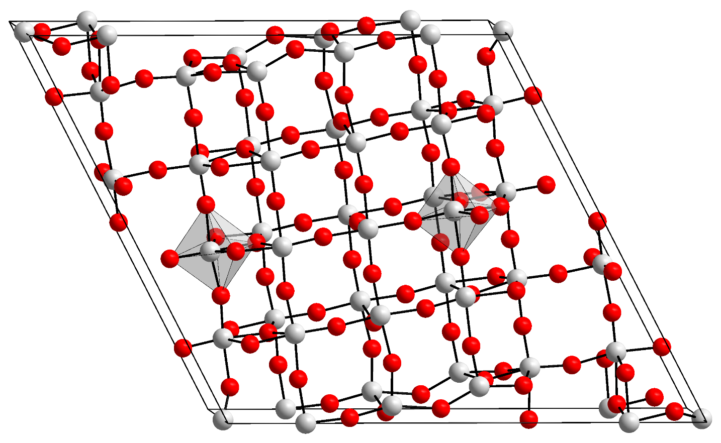
Figure 1. orthorhombic structure of T-Nb2O5, lithium ions can travel through the space between atoms above. |
Another method is EIS mapping, which is very useful for determining impedance contributions from EDLC and pseudocapacitance. The test was carried out by applying an AC current of 10mV on the T-Nb2O5-NiO electrode in the chamber and vary the frequency of the AC current from 1kHz to 1MHz. The resulting current density at some point is composed of migration, diffusion, and convection term at different voltage steps. A Nyquist plot can be mapped by simply dividing the potential V (ω) by the instantaneous current i(ω) , get the impedance Z. The magnitude of the impedance Z0 equals to the potential amplitude E0 divided by the current amplitude i0. Plot the vector Z with magnitude Z0 on a 2-D plot while its real part (x component on a 2-D coordinate) is the impedance get from measured V/i at a certain time, which symbols the resistance simply forms R=V/i; its imaginary part (y component) is the active part that comes from the capacitors or limits of ion/electron diffusion. A fast ion diffusion and smaller resistance reflect in the imaginary region at the first half circle but not the real region in a pseudocapacitor half-cell. After the first cycles a fastened ion diffusion will shows up with a smaller impedance.
To test how the pseudocapacitive part and the EDLC part contribution to the whole battery, two variant controlled experiments are performed: capacitive charge storage process which focuses on the surface capacitance; and ion diffusion-controlled process which targets at the diffusion of the ions in the electrodes. The instantaneous current at different scan rate is measured and is compared to Cottrell’s equation of battery like behaviors and capacitor like behaviors. [5] After linearization, the equation for capacitive materials is:
\( i(v)={k_{1}}v+{k_{2}}\sqrt[]{v} \)
While in a pseudocapacitor, the instantaneous current versus instantaneous voltage becomes:
\( \frac{i(v)}{\sqrt[]{v}}={k_{1}}\sqrt[]{v}+{k_{2}} \)
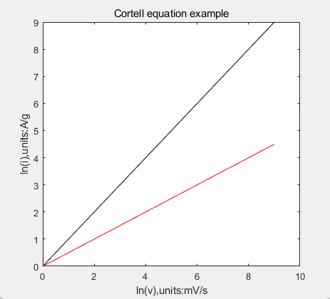
A simpler way to identify is take logarithm of both i and v, make a plot of ln(i) versus ln(v), if the slope is near 0.5, it is pseudocapacitive; if the slope nears 1, it is more EDLC mechanism.
| |
Figure2. the Cortell equation ln(i) versus ln(v) of EDLC (black, slope=1) and pseudocapacitive (red, slope=0.5) mechanisms. | |
To test how the doping level of the cathode material affect the performance of the pseudocapacitor, dope the cathode with same synthesis procedure I mentioned before with different ratios of NiO :(3,6,10,20,30 percents). Use same tests (CV and GCD) to conclude its capacity, energy density and power density.
As the temperature changes, the doped structure of T-Nb2O5-NiO electrode may not be orthorhombic anymore, may even collapse at higher temperature and cannot be conductive. As a result, changing the reaction condition is an important method to test the actual functionality of the T-Nb2O5-NiO pseudocapacitor. For instance, changing the environmental temperature and test the performance of the cell. Set the environmental temperature to 0◦C, 10◦C, 20◦C, and 50◦C, and use CV and GCD cycles to experiment the capacity, energy density and power density at each temperature. There will be one or more temperature to optimize the Coulombic efficiency because the holes of the cathode porous structure may be optimized to fit in lithium ions or at this temperature the conductivity is optimized.
3. Conclusion and discussion
In this research I have dived into the doping method of NiO to T-Nb2O5 as a pseudocapacitor’s cathode and tested how the different doping levels affect the Coulombic efficiency as well as the impedance. Also I tested the full cell’s performance in its capacitance, impedance and power / energy density. As a conclusion, popular cathode materials have many possibilities to improve in many aspects, and targeting problems like a smaller energy density than lithium-ion batteries are direct and clear. With the target and problem may meet, researchers can use methods like doping or using new adhering methods to make more porous structure and generate a bigger surface area can improve the performance. Lithium-ion batteries, in contrast have smaller areas to improve because it is already a mature technology. By studying the natures of pseudocapacitors and Lithium-ion batteries, I inspected that some areas like car batteries or laptop batteries will remain lithium ion while they need to perform a longer operation time, while some accessories and phones can use pseudocapacitors as their energy support which is more time-saving when charging. Pseudocapacitors’ energy density cannot exceed Lithium-ion batteries not because lacking in technology or researches, just because Lithium is the least heavy metal and performs best energy density theoretically by simple calculations, which no metal can exceed it. However, a pseudocapacitor has its own advantage which remains high power density just like a EDLC and exceeds EDLC as its energy density is comparable with lithium-ion batteries.
References
[1]. Liaona She, Zhe Yan, Liping Kang. nanoparticles anchored on an n-doped graphene hybrid anode for a sodium-ion capacitor with high energy density. ACS Omega, 2018.
[2]. Yudi Wei, M Zheng, W Luo.All pseudocapacitive mxene-mno2 flexible asymmetric supercapacitor. journal of energy storage, 2021.
[3]. Jang Wook Choi, Doron Aurbach. Promise and reality of post-lithium-ion batteries with high energy densities. nature, 2016.
[4]. Lingping Kong, Chuanfang Zhang, Jitong Wang. Free-standing t-nb2o5/graphene composite papers with ultrahigh gravimetric/volumetric capacitance for li-ion intercalation pseudocapacitor. ACS Nano, 2015.
[5]. GuyDenuault, Michael V.Mirkin, Alien J.Bard1. Direct determination of diffusion coefficients by chromoamperometery at microdisk electrodes. Electroano.Chem, 1991.
Cite this article
Ji,J. (2023). Nickel-rich T-Nb2O5 Electrodes for Optimal Pseudocapacitive Charge Storage. Applied and Computational Engineering,3,345-349.
Data availability
The datasets used and/or analyzed during the current study will be available from the authors upon reasonable request.
Disclaimer/Publisher's Note
The statements, opinions and data contained in all publications are solely those of the individual author(s) and contributor(s) and not of EWA Publishing and/or the editor(s). EWA Publishing and/or the editor(s) disclaim responsibility for any injury to people or property resulting from any ideas, methods, instructions or products referred to in the content.
About volume
Volume title: Proceedings of the 3rd International Conference on Materials Chemistry and Environmental Engineering (CONF-MCEE 2023)
© 2024 by the author(s). Licensee EWA Publishing, Oxford, UK. This article is an open access article distributed under the terms and
conditions of the Creative Commons Attribution (CC BY) license. Authors who
publish this series agree to the following terms:
1. Authors retain copyright and grant the series right of first publication with the work simultaneously licensed under a Creative Commons
Attribution License that allows others to share the work with an acknowledgment of the work's authorship and initial publication in this
series.
2. Authors are able to enter into separate, additional contractual arrangements for the non-exclusive distribution of the series's published
version of the work (e.g., post it to an institutional repository or publish it in a book), with an acknowledgment of its initial
publication in this series.
3. Authors are permitted and encouraged to post their work online (e.g., in institutional repositories or on their website) prior to and
during the submission process, as it can lead to productive exchanges, as well as earlier and greater citation of published work (See
Open access policy for details).
References
[1]. Liaona She, Zhe Yan, Liping Kang. nanoparticles anchored on an n-doped graphene hybrid anode for a sodium-ion capacitor with high energy density. ACS Omega, 2018.
[2]. Yudi Wei, M Zheng, W Luo.All pseudocapacitive mxene-mno2 flexible asymmetric supercapacitor. journal of energy storage, 2021.
[3]. Jang Wook Choi, Doron Aurbach. Promise and reality of post-lithium-ion batteries with high energy densities. nature, 2016.
[4]. Lingping Kong, Chuanfang Zhang, Jitong Wang. Free-standing t-nb2o5/graphene composite papers with ultrahigh gravimetric/volumetric capacitance for li-ion intercalation pseudocapacitor. ACS Nano, 2015.
[5]. GuyDenuault, Michael V.Mirkin, Alien J.Bard1. Direct determination of diffusion coefficients by chromoamperometery at microdisk electrodes. Electroano.Chem, 1991.