


1.Introduction
The study of the forces that air and other gases exert on object motion is the focus of the aerodynamics branch of aeronautical mechanics. Low Reynolds (Re) numbers apply to structures and equipment used in both military and civilian applications, including wind turbines, gliders, unmanned aerial vehicles, and tiny aerial vehicles [1]. Any aerofoil’s aerodynamic properties must be examined, which is why several aerodynamics-related parameters must be studied both experimentally and numerically to achieve the necessary aerofoil performance [2].
The origins of wing development can be traced back to the late 1800s, a period marked by the beginning of systematic flight studies [3]. As aircraft technology progressed, the design of aerofoils became essential for performance optimization [4]. Initial designs relied heavily on experimental methods; however, with improvements in aerodynamic theory, researchers began to investigate how various aerofoil configurations influenced lift and drag forces. In the 1930s, the National Advisory Committee for Aeronautics (NACA) launched its series of aerofoils, providing mathematical definitions for their shapes used in aircraft design [5]. Notably, the NACA2412 is a classic aerofoil that is widely used in aerodynamic research and engineering, especially in aviation and wind energy [3]. The aerofoil has a moderately curved design that provides a good balance between lift and drag, so it excels when studying aerodynamics. The NACA2412 aerofoil is 12% thick at the chord length, a ratio that makes it stable in low and moderate airflow and is often used in general aviation and light aircraft designs. The shape of the NACA2412 features notable curvature that enhances its lift capabilities while keeping the drag coefficient low. This characteristic contributes positively to the overall aerodynamic efficiency of aircraft utilizing this aerofoil. Because of its reliable performance and suitability for numerical simulations, NACA2412 is often selected for computational fluid dynamics (CFD) investigations [6]. For instance, during fluid dynamic simulations, models based on NACA2412 are commonly input into software like Fluent to analyze their aerodynamic responses at various angles of attack and Reynolds numbers [7,8].
In this research project, the aerodynamic characteristics of the NACA2412 were examined through two-dimensional numerical simulations that encompass mesh generation, boundary condition configurations, and comprehensive analysis of convective flow patterns. A structured mesh approach was employed during the meshing process. In which a finer mesh is used in the area around the aerofoil to better simulate the movement of the airflow, thus improving the accuracy of the calculation [9]. In the division of computing domains, a ‘C’ type computing domain is adopted and divided into six subdomains to optimize computing efficiency and reduce computing costs [10]. The research of NACA2412 provides an important theoretical basis for understanding its aerodynamic characteristics under different flow conditions, which can not only provide guidance for the design of aircraft but also provide a reference for the development and testing of new airfoils [11].
2.Method
2.1.Geometric modelling and calculation domain
This study chooses NACA2412 as a research object. The geometry for CFD simulation is created by importing aerofoil geometry coordinates into Fluent. For this aerofoil, the chord length is 1 m. The 'C' shape has a radius of 8 meters. Figure 1 depicts the airfoil utilized in this investigation. Figure 2 shows the computational domain. The inlet and outlet parts specify the speed inlet and pressure outflow.
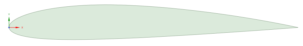
Figure 1: NACA 2412 Airfoil.
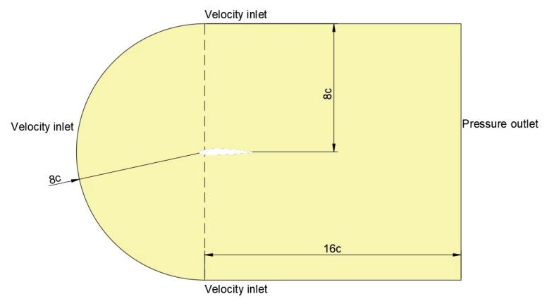
Figure 2: Computational domain.
2.2.Mesh division
The quality of the grid system directly influences the accuracy of numerical results. Therefore, the mesh generation method used in this paper for the aerofoil and computation domain is 2D structured mesh. To better simulate the flow field motion, the ‘C’ type computational domain is used in the present study. The domain is divided into 6 subdomains. To optimize computing efficiency and reduce computing cost, the outer domain adopts coarser cell side lengths for grid processing. To properly depict the movement of the airflow, a tiny mesh is employed around the aerofoil. The mesh generation at the domain is depicted in Figure 3. Figure 4 shows local details around the aerofoil.
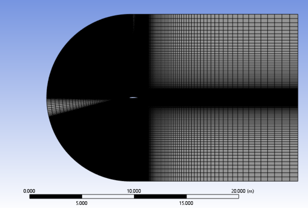
Figure 3: Meshing Domain for NACA 2412 Airfoil.
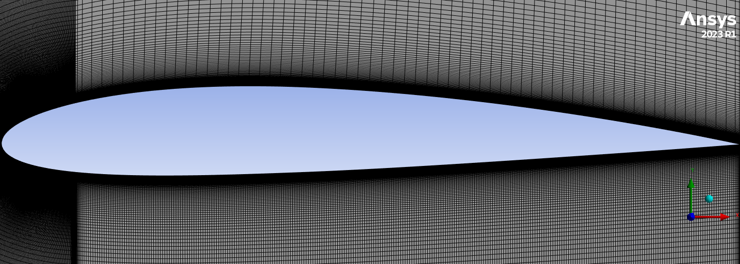
Figure 4: Details close to the aerofoil.
2.3.Boundary conditions and control programs
Boundary conditions refer to the characteristic physical properties or conditions on the surface of a region that represent a specific flow variable of a physical model. During the CFD simulation, 1000 iterations and 10-6 iteration errors are selected to increase the precision of numerical results and guarantee result convergence. The boundaries used in this calculation are shown in table 1 below.
Table 1: Solver Setting.
|
General |
Solver |
Pressure-Based |
|
Time |
Steady |
|
|
Model |
Viscous model |
k-omega SST |
|
Material |
Air |
|
|
Density |
1.225kg/m³ |
|
|
Boundary Conditions |
Angel of attack |
0-20° |
|
Solution Methods |
Scheme |
Coupled |
|
Pressure |
Second Order |
|
|
Momentum |
Second Order Upwind |
|
|
Turbulent Kinetic Energy |
Second Order Upwind |
|
|
Solution |
Initialization |
Hybrid Initialization |
|
Calculation |
Number of iterations |
1000 |
The two-dimensional incompressible flow equation of the flow through a flat wing is given below.
Mass conservation equation:
The mathematical form of the equation can be expressed as follows:
\( \frac{∂u}{∂x}+\frac{∂ν}{∂y}=0 \)(1)
Momentum Conservation Equation:
x-direction
\( \frac{∂u}{∂t}+\frac{∂({u^{2}})}{∂x}+\frac{∂(uν)}{∂y}=-\frac{1}{ρ}\frac{∂P}{∂x}+υ(\frac{{∂^{2}}u}{∂{x^{2}}}+\frac{{∂^{2}}u}{∂{y^{2}}}) \)(2)
y-direction
\( \frac{∂ν}{∂t}+\frac{∂(uν)}{∂x}+\frac{∂({ν^{2}})}{∂y}=-\frac{1}{ρ}\frac{∂P}{∂y}+υ(\frac{{∂^{2}}ν}{∂{x^{2}}}+\frac{{∂^{2}}ν}{∂{y^{2}}}) \)(3)
3.Result and discussion
In this paper, the data of NACA2412 is obtained by using simulation results for various angles of attack and Reynolds numbers using k-omega SST modelling. The aerofoil was first calculated when the Reynolds number is 20000,50000,100000 and the Angle of attack is 0°. The model is solved with a range of different angles of attack 0°, 2.5°, 5°, 7.5°, 10°, 12.5°, 15° and at two different Reynolds numbers of 1.7106 and 2.2106.
3.1.Effect of Re on CL and CD
In this section, the study examines the flow field at an Angle of attack of α=0° and Reynolds numbers (Re) of 20000, 50000, and 100000, respectively. Figure 5, Figure 6 and Figure 7 show the velocity field and pressure field respectively when Re=20000, 50000, 100000.
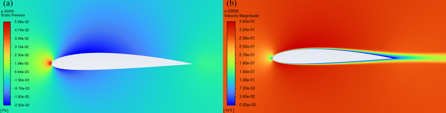
Figure 5: Pressure and Velocity Contours of NACA2412 that Re=20000.
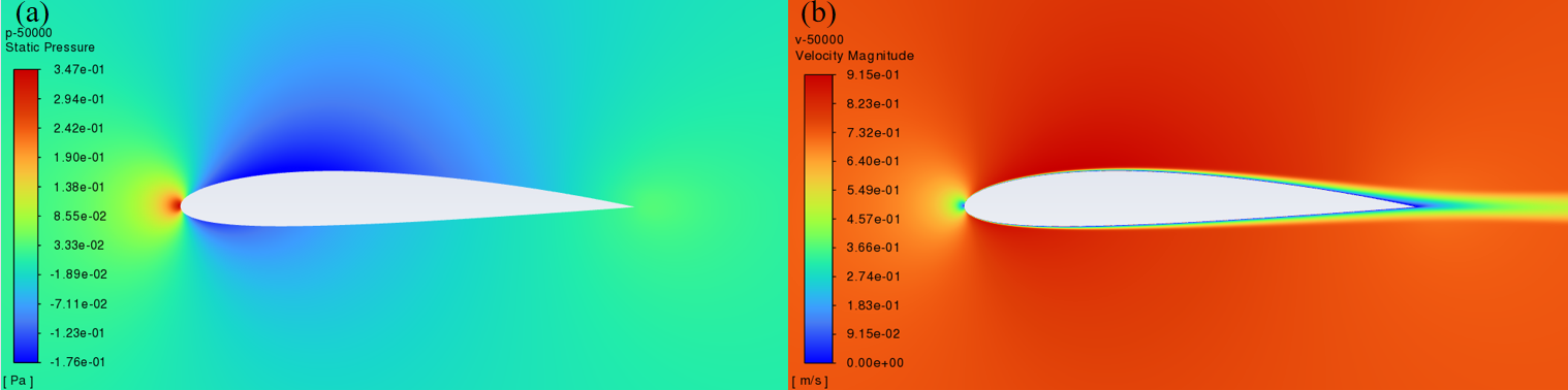
Figure 6: Pressure and Velocity Contours of NACA2412 that Re=50000.
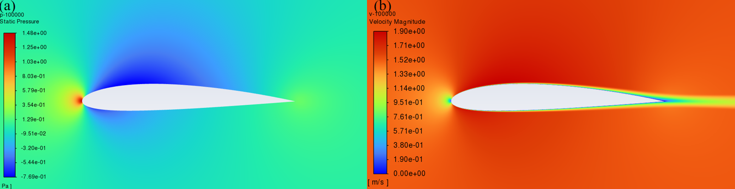
Figure 7: Pressure and Velocity Contours of NACA2412 that Re=100000.
To verify the results obtained, Fluent was used to calculate the lift and drag coefficient at Reynolds number (Re) of 20000, 50000 and 100000. The results are shown in table 2.
Table 2: Coefficients of lift and drag at Reynolds number.
|
Re |
CL |
CD |
|
20000 |
9.3710\( { ^{-6}} \) |
2.410\( { ^{-6}} \) |
|
50000 |
8.0710\( { ^{-5}} \) |
1.0710\( { ^{-5}} \) |
|
100000 |
0.00038 |
3.7910\( { ^{-5}} \) |
As CL increased, table 2 shows that the Reynolds number increased as well. This is due to the relatively large viscous effects at lower Reynolds numbers, which limit the maximum lift and create significant drags. Because the turbulent boundary layer transports more energy than the viscous boundary layer, CD develops substantially more. Table 2 comparison confirms that CD increases as Reynolds number increases.
3.2.Effect of Angel of Attack and Re on CL and CD
Variations in AOA affect the airfoil's rise and fall. The numerical findings for the lift coefficient at different Re values with an angle of attack ranging from 0° to 20° are displayed in Figure 8. The lift coefficient rises as the angle of attack does. The lift coefficient is at its highest when 15° is the angle of attack. Nevertheless, the lift coefficient rapidly decreases as the angle of attack increases higher. The lift coefficient at high Reynolds numbers is consistently greater than the lift coefficient at low Reynolds numbers over the whole angle of attack range. At a high Reynolds number, the lift coefficient's decline rate is significantly greater than at a low Reynolds.
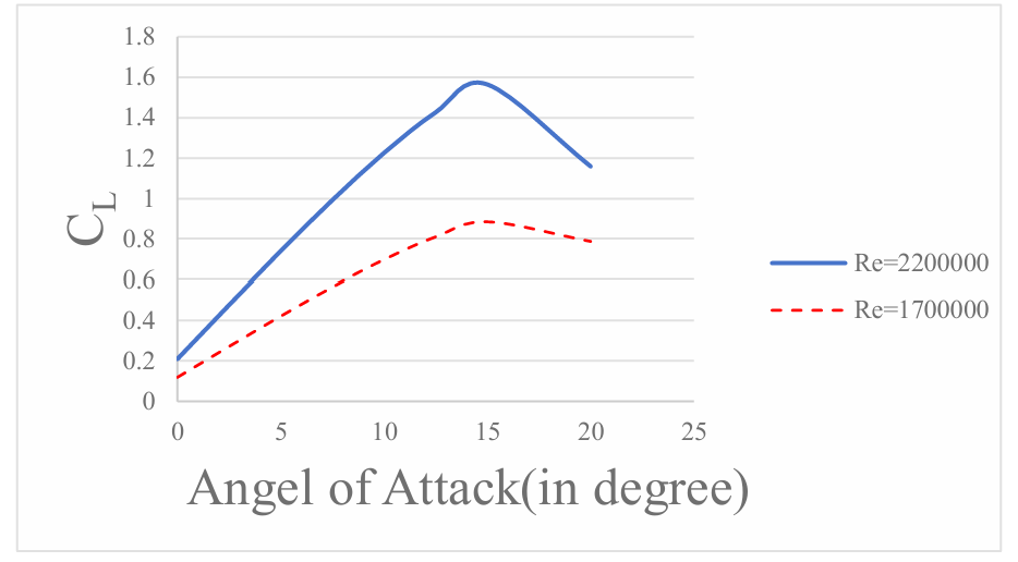
Figure 8: Lift coefficient against Angel of Attack at different Re numbers.
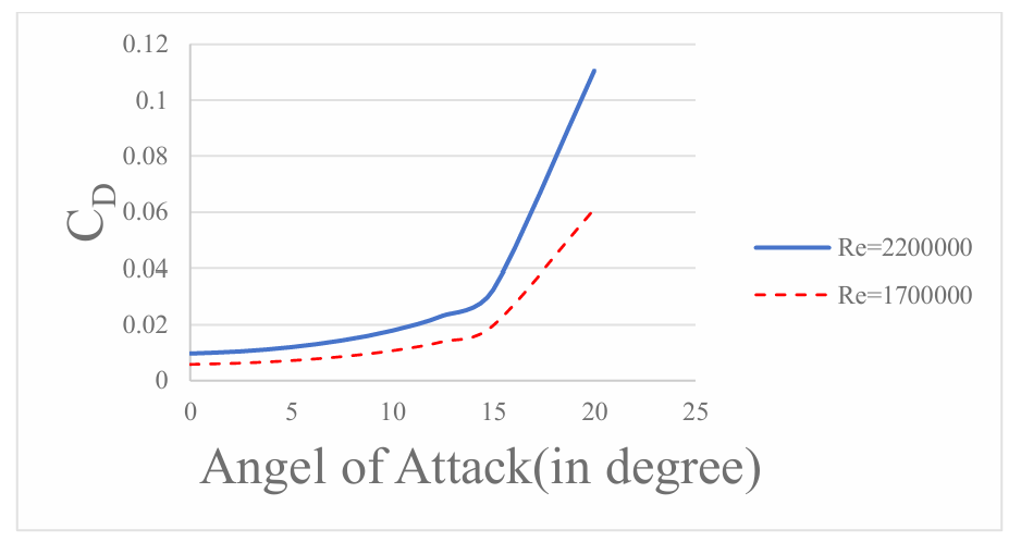
Figure 9: Drag coefficient against Angel of Attack at different Re numbers.
Figure 9 demonstrates that the drag coefficient increases with the increase of the angle of attack and the effects of Re. The drag coefficient suddenly rises sharply at 15 degrees, which is due to the stall conditions. Similarly, the drag coefficient is higher at high Reynolds numbers.
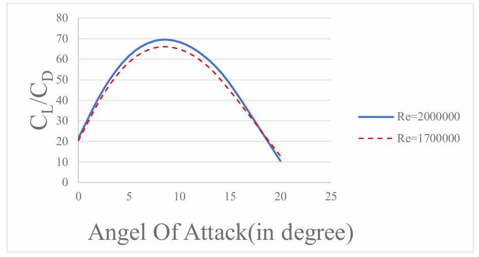
Figure 10: CL/CD against Angel of Attack at different Re numbers
From Figure 10, before reaching the highest point, the ratio is proportional to the Reynolds number and the Angle of attack. The maximum value of the high Reynolds number is slightly larger than that of the low Reynolds number due to the velocity. With the increase of the angle of attack and the occurrence of flow separation, the CL/CD ratio declines. At about 17 degrees, the CL/CD ratio for Re=1700000 is greater than that for Re=1700000.
4.Conclusion
In this research, a numerical study was conducted on the effects of different Reynolds numbers on the aerodynamic properties of the NACA2412 aerofoil for various angles of attack. With the increase of Reynolds number, the lift coefficient and the CL/CD ratio both increases. It is shown that the aerofoil has higher lift characteristics at high Reynolds number. With the increase of the angle of attack, the lift coefficient of the aerofoil decreases while the drag coefficient increases for different Reynolds numbers. This phenomenon is mainly due to the transformation of the flow into turbulence, which causes the separation of the boundary layer to occur earlier. As a result, the aerodynamic performance is impacted. As the angle of attack increases, the CL/CD ratio rises linearly. Nevertheless, the CL/CD ratio abruptly decreases when a specific angle of attack is attained. Thus, one of the main elements influencing an airfoil's lift and drag is its angle of attack. An essential theoretical foundation for airfoil design and aerodynamic performance optimization is provided by this study's theoretical significance, which reveals the impact of Reynolds number and angle of attack on the NACA2412 airfoil's aerodynamic performance. In terms of practical significance, the research results can guide aircraft aerofoil design, wind energy utilization, fluid machinery design and other fields. It can help to improve the aerodynamic efficiency and performance of aircraft and promote technical progress and application development in related fields. The variation of flow characteristics under different Reynolds numbers and Angles of attack is complicated, especially since the study of the stall phenomenon needs accurate experiments and numerical simulation. Theoretical models may have limited applicability under complex flow conditions and need to be constantly calibrated and validated.
Acknowledgements
All the authors contributed equally, and their names were listed in alphabetical order.
References
[1]. Menter, F. R. (1994). Two-equation eddy-viscosity turbulence models for engineering applications. AIAA Journal, 32(8), 1598–1605. https://doi.org/10.2514/3.12149
[2]. Ayat Abdulhussien Molaa, & Mohammed A. Abdulwahid (2024). Numerical and experimental study of the impact on aerodynamic characteristics of the NACA0012 aerofoil. Open Engineering, 14 (1), 0-0. https://doi.org/10.1515/eng-2022-0506
[3]. Abbott,I.H.Von Doenhoff, A.E. (1959). Theory of Wing Sections: Including a Summary of Airfoil Data. Dover Publications.
[4]. Anderson, J.D. (1999). Aircraft Performance and Design. McGraw-Hill Education.
[5]. Jones, R.T. (1934). Theoretical Characteristics of Cambered Airfoils. National Advisory Committee for Aeronautics (NACA).
[6]. Joseph Katz, & Allen Plotkin (1991). Low-speed aerodynamics: from wing theory to panel methods. null, 0 (0), 0-0. https://doi.org/null
[7]. Fluent, Inc. (2006). Fluent User’s Guide. Fluent Inc.
[8]. Hendrik K. Versteeg, & Weeratunge Malalasekera (2006). An introduction to computational fluid dynamics : the finite volume method. null, 0 (0), 0-0. https://doi.org/null
[9]. White, F.M. (2006). Viscous Fluid Flow (3rd ed.). McGraw-Hill Education.
[10]. Drela, M. (1989). XFOIL: An Analysis and Design System for Low Reynolds Number Airfoils. AIAA Journal, 21(6), 456-460.
[11]. Cebeci, T., & Bradshaw, P. (1977). Momentum Transfer in Boundary Layers. Hemisphere Publishing Corporation.
Cite this article
Gu,Z.;Wang,G. (2025). Effect of Reynolds Number and Angle of Attack on Aerodynamic Performance of NACA2412. Applied and Computational Engineering,130,50-57.
Data availability
The datasets used and/or analyzed during the current study will be available from the authors upon reasonable request.
Disclaimer/Publisher's Note
The statements, opinions and data contained in all publications are solely those of the individual author(s) and contributor(s) and not of EWA Publishing and/or the editor(s). EWA Publishing and/or the editor(s) disclaim responsibility for any injury to people or property resulting from any ideas, methods, instructions or products referred to in the content.
About volume
Volume title: Proceedings of the 5th International Conference on Materials Chemistry and Environmental Engineering
© 2024 by the author(s). Licensee EWA Publishing, Oxford, UK. This article is an open access article distributed under the terms and
conditions of the Creative Commons Attribution (CC BY) license. Authors who
publish this series agree to the following terms:
1. Authors retain copyright and grant the series right of first publication with the work simultaneously licensed under a Creative Commons
Attribution License that allows others to share the work with an acknowledgment of the work's authorship and initial publication in this
series.
2. Authors are able to enter into separate, additional contractual arrangements for the non-exclusive distribution of the series's published
version of the work (e.g., post it to an institutional repository or publish it in a book), with an acknowledgment of its initial
publication in this series.
3. Authors are permitted and encouraged to post their work online (e.g., in institutional repositories or on their website) prior to and
during the submission process, as it can lead to productive exchanges, as well as earlier and greater citation of published work (See
Open access policy for details).
References
[1]. Menter, F. R. (1994). Two-equation eddy-viscosity turbulence models for engineering applications. AIAA Journal, 32(8), 1598–1605. https://doi.org/10.2514/3.12149
[2]. Ayat Abdulhussien Molaa, & Mohammed A. Abdulwahid (2024). Numerical and experimental study of the impact on aerodynamic characteristics of the NACA0012 aerofoil. Open Engineering, 14 (1), 0-0. https://doi.org/10.1515/eng-2022-0506
[3]. Abbott,I.H.Von Doenhoff, A.E. (1959). Theory of Wing Sections: Including a Summary of Airfoil Data. Dover Publications.
[4]. Anderson, J.D. (1999). Aircraft Performance and Design. McGraw-Hill Education.
[5]. Jones, R.T. (1934). Theoretical Characteristics of Cambered Airfoils. National Advisory Committee for Aeronautics (NACA).
[6]. Joseph Katz, & Allen Plotkin (1991). Low-speed aerodynamics: from wing theory to panel methods. null, 0 (0), 0-0. https://doi.org/null
[7]. Fluent, Inc. (2006). Fluent User’s Guide. Fluent Inc.
[8]. Hendrik K. Versteeg, & Weeratunge Malalasekera (2006). An introduction to computational fluid dynamics : the finite volume method. null, 0 (0), 0-0. https://doi.org/null
[9]. White, F.M. (2006). Viscous Fluid Flow (3rd ed.). McGraw-Hill Education.
[10]. Drela, M. (1989). XFOIL: An Analysis and Design System for Low Reynolds Number Airfoils. AIAA Journal, 21(6), 456-460.
[11]. Cebeci, T., & Bradshaw, P. (1977). Momentum Transfer in Boundary Layers. Hemisphere Publishing Corporation.