


1. Introduction
With the increasing demand for high-precision machining and inspection, especially in fields like semiconductor manufacturing, such as wafer and silicon processing and inspection, motion stages are required to achieve higher precision and stability. Traditional motion stages are prone to vibrations caused by their own movement or external forces [1], which affect machining accuracy. In contrast, compliant motion stages can effectively reduce vibrations and enhance precision through flexible support structures and advanced drive monitoring technologies.
From the perspective of complex motion requirements, certain specialized applications demand motion stages with strict orthogonality in planar motion directions or precise micro-rotational motion in the vertical direction. Traditional air-bearing stages struggle to meet these demands, while compliant motion stages can achieve more complex motion functionalities through structural designs such as flexible connections and ball-joint mountings.
According to current research, continuous structural optimization of compliant motion stages has been a focus for researchers. For example, Suzhou Xihang Semiconductor Technology Co., Ltd. has proposed a compliant motion stage combining components such as support beams, end connectors, air-floating feet, side air-floating pads, and side brake pads, enabling flexible support for the beams and precise spatial positioning. In terms of precision improvement, the iFM intelligent compliant motion system by DaHuan Robotics achieves a repeatability of ±5 µm. Regarding speed and acceleration, it achieves a maximum acceleration of 40 m/s². Advanced control algorithms and technologies are employed in compliant motion stages to realize more precise motion control and vibration suppression.
This study involves the fundamental mechanical properties of materials, including elastic modulus, Poisson’s ratio, and yield strength. Through theoretical calculations and simulation analyses [2]-[4], materials meeting the basic performance requirements of compliant motion stages [5],[6] (e.g., withstanding specific loads and achieving designated deformation levels) were preliminarily selected. Theoretical stiffness models were developed for single-parallelogram, mirrored single-parallelogram, double-parallelogram, and mirrored double-parallelogram compliant mechanisms. Finite element analysis (FEA) was employed to precisely simulate the deformation behavior of different aluminum compliant mechanisms under varying loads, and force-displacement curves were plotted to obtain the actual stiffness data of the designed compliant mechanisms.
2. Modeling and Analysis of Compliant Motion Mechanisms
Compliant mechanisms are a novel type of mechanism that primarily utilize the elastic deformation of components to transmit motion or force [7]. Unlike traditional rigid mechanisms, the components of compliant mechanisms possess a certain degree of flexibility. During operation, these flexible components undergo recoverable deformation to achieve specific functions. From a materials perspective, compliant mechanisms often employ materials with excellent elasticity. These mechanisms offer significant advantages, such as reducing friction and wear between moving parts and enabling more complex motion trajectories. Moreover, they play a critical role in applications requiring high precision and small displacements.
The goal of this modeling effort is to accurately describe the mechanical behavior, motion characteristics, and interactions with external environments of compliant motion stages through mathematical and physical models. This provides a theoretical foundation and analytical tools for experimental design, performance prediction, control strategy formulation, and optimization research.
2.1. Double Parallelogram Mechanism
When an external force F is applied to a double parallelogram mechanism in its initial stage (as shown in Figure 1), the total deformation of the mechanism can be observed. Calculating the stiffness of the mechanism is crucial for comprehensively understanding the characteristics of the mechanism under external forces and evaluating its performance in practical applications. Such calculations help accurately predict the deformation of the mechanism during operation, providing critical data for engineering design and practical production. This ensures that the mechanism meets specific application requirements and quality standards.
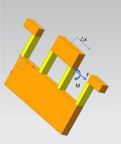
Figure 1: Double Parallelogram Compliant Mechanism
It is worth noting that each component of the mechanism is subjected to a combination of moment M and force F. Under these conditions, and considering the boundary conditions of rotational and translational motion, the following relationships can be derived:
\( 0=\frac{Fl}{2EI}-\frac{Ml}{EI} \) (1)
\( δx=\frac{{FL^{3}}}{3EI} \) - \( \frac{{Ml^{2}}}{2EI} \) (2)
where \( ∆ \) x represents the transverse deflection, E is the material’s Young’s modulus, and I = bh^3/12 is the moment of inertia of the cross-section about the neutral axis.
\( F=\frac{2M}{L} \) (3)
\( ∆x=\frac{{Fl^{3}}}{12EI} \) (4)
Since the four flexible components have the same length l, the above relationships hold, i.e., δx = △x/2 , where △x represents the displacement on one side of the double parallelogram compliant mechanism. Based on these known conditions and derived relationships, the stiffness of the mechanism in the direction of the applied force can be further calculated, as shown in equation (5). This stiffness calculation is crucial for comprehensively understanding the characteristics of the mechanism under external forces and evaluating its performance in practical engineering applications:
K= \( \frac{{F_{x}}}{∆x} \) = \( \frac{2F}{2δx} \) = \( \frac{Eb{h^{3}}}{{l^{3}}} \) (5)
2.2. Single Parallelogram Mechanism
The elastic modulus, Poisson’s ratio, density, and other parameters of the material used in the compliant motion stage are obtained through material tests and used as inputs for the model. The stiffness k of a single parallelogram mechanism (as shown in Figure 2) is twice that of the double parallelogram mechanism, i.e., 2K. Boundary conditions for the model, such as fixed constraints and sliding constraints, are determined based on the actual installation and operating conditions of the experiment. Additionally, loading parameters such as driving forces and load forces are set according to the loading scheme designed for the experiment.
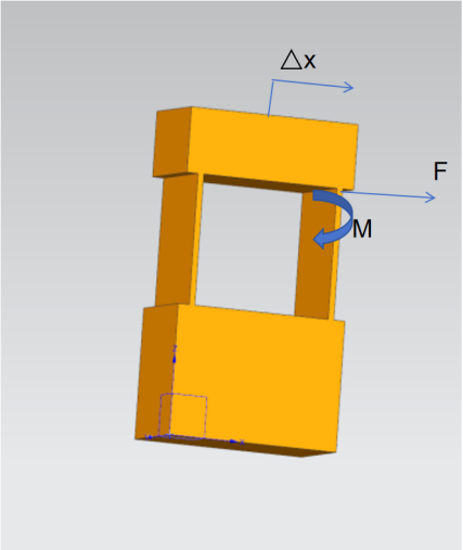
Figure 2: Single Parallelogram Compliant Mechanism
2.3. Mirrored Single Parallelogram Mechanism
The actual installation method of the compliant motion stage in the experimental setup determines which parts are fully fixed. For example, if the motion stage is bolted to a rigid base, the nodes corresponding to the bolted connections in the model are set with full displacement constraints. This means no displacement is allowed in the three translational directions (x,y,z) or the three rotational directions (θx, θy, θz). The upper and lower parts of the mechanism provide structural support. The theoretical stiffness k of the mirrored single parallelogram mechanism (as shown in Figure 3) is four times that of the single parallelogram mechanism, i.e., 4K.
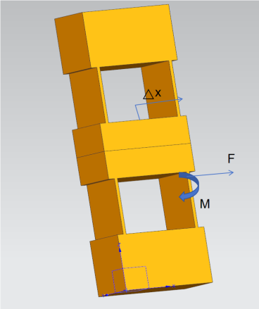
Figure 3: Mirrored Single Parallelogram Compliant Mechanism
2.4. Mirrored Double Parallelogram Mechanism
The external loads experienced by the compliant motion stage during actual operation, such as the weight of transported objects or cutting forces during processing, are considered. The magnitude, direction, and application point of the load forces are determined using force sensors or theoretical calculations and are applied in the model accordingly. For instance, in an experiment simulating the motion stage transporting heavy objects, the load force is determined based on the object’s mass and gravitational acceleration. This load is then applied to the contact area between the motion stage and the object to analyze the mechanical performance and deformation of the motion stage under the applied load. The theoretical stiffness k of the mirrored double parallelogram mechanism (as shown in Figure 4) is twice that of the double parallelogram mechanism, i.e., 2K.
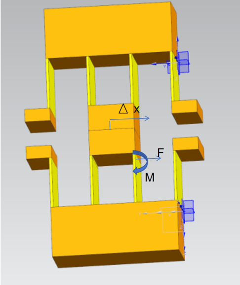
Figure 4: Mirrored Double Parallelogram Compliant Mechanism
3. Simulation Data
The finite element model is used to discretize the structure of the compliant motion stage. Based on the principles of mechanics of materials and elasticity theory, the mechanical relationships between nodes and elements are constructed to simulate the stress-strain distribution and deformation under different loads (e.g., gravity, driving force, frictional force). The finite element model is chosen due to the complex structure of the compliant motion stage, involving multiple materials and intricate geometries. The finite element method effectively handles such complexity, providing detailed local and global mechanical information.
The model is created using the engineering simulation software ANSYS. First, the material properties of aluminum, such as density and elastic modulus, are configured in ANSYS. The UG model is then imported into the ANSYS software, and the material is set to aluminum. A Cartesian coordinate system is established. The surface of the model is meshed, with the grid size for the beams being half the size of the rest. The static structure of the model is then edited by selecting the support surface and the load surface. A load of 10 N is applied perpendicular to the beam’s surface outward, incremented in 10 steps of 1 N each. Finally, simulation data are solved and compared with theoretical values to observe the relationship between the two datasets.
3.1. Single Parallelogram Mechanism
In the single parallelogram compliant motion mechanism (as shown in Figure 5), the dimensions of the beam are 1mm*20mm*20mm. The UG model is imported into ANSYS, and the material is set to aluminum, with its hardness and elastic modulus data improved. A Cartesian coordinate system is established [8]-[10], and the grid size is set to 0.5mm*0.5mm. The right side of the model is chosen as the support surface, and a force perpendicular to the surface is applied inward. The force magnitude ranges from 1 to 10 N, divided into ten steps, with each step increasing by 1 N. The stiffness values are solved, and a finite element analysis curve is obtained. The finite element analysis deformation results for the single parallelogram mechanism are shown in Figure 5, and the finite element analysis data results are shown in Figure 6.
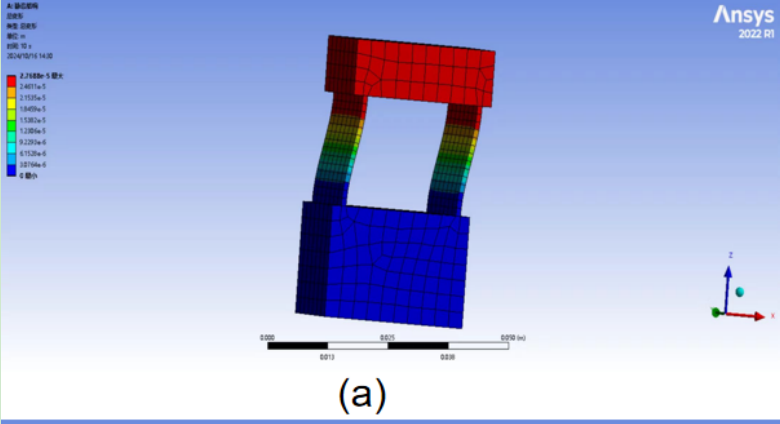
Figure 5: Finite Element Analysis Deformation Results of Single Parallelogram Compliant Mechanism

Figure 6: Finite Element Analysis Data Results of Single Parallelogram Compliant Mechanism
By substituting the dimensions into theoretical formula (5), the theoretical stiffness calculation result is obtained as shown in formula (6):
` \( {K_{1}} \) = \( \frac{{2Ebh^{3}}}{{l^{3}}} \) =3.55× \( {10^{5}} \) N/m (6)
Based on simulation results, the stiffness calculation result is as follows:
\( {K \prime _{1}} \) = \( \frac{1}{2.7688×{10^{-6}}} \) N/m=3.612× \( {10^{5}} \) N/m (7)
After calculation, the deviation between the theoretical stiffness and simulated stiffness of the single parallelogram compliant mechanism is 1.9%.
3.2. Mirrored Single Parallelogram Mechanism
In the mirrored single parallelogram compliant motion mechanism (as shown in Figure 7), the beam dimensions are 1mm*20mm*20mm (the dimensions of all four beams are identical). The UG model is imported into ANSYS, and the material is set to aluminum, with its hardness and elastic modulus data improved. A Cartesian coordinate system is established [8]-[10], and the grid size is set to 0.5mm*0.5mm. The right side of the model is chosen as the support surface, and a force perpendicular to the surface is applied inward. The force magnitude ranges from 1 to 10 N, divided into ten steps, with each step increasing by 1 N. The stiffness values are solved, and a finite element analysis curve is obtained.
The finite element analysis deformation results for the mirrored single parallelogram mechanism are shown in Figure 7, and the finite element analysis data results are shown in Figure 8.
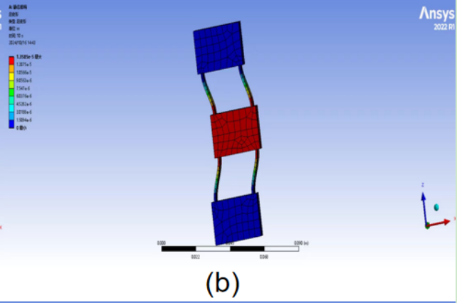
Figure 7: Finite Element Analysis Deformation Results of Mirrored Single Parallelogram Compliant Mechanism
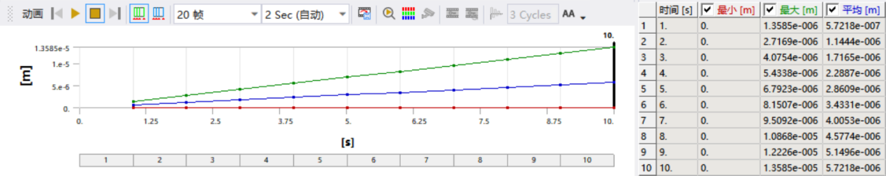
Figure 8: Finite Element Analysis Data Results of Mirrored Single Parallelogram Compliant Mechanism
By substituting the dimensions into theoretical formula (5), the theoretical stiffness calculation result is obtained as shown in formula (8):
\( {K_{2}} \) = \( \frac{{4Ebh^{3}}}{{l^{3}}} \) =7.1× \( {10^{5}} \) N/m (8)
Based on simulation results, the stiffness calculation result is as follows:
\( {K \prime _{2}} \) = \( \frac{1}{1.3585×{10^{-6}}} \) N/m=7.361× \( {10^{5}} \) N/m (9)
After calculation, the deviation between the theoretical stiffness and simulated stiffness of the mirrored single parallelogram compliant mechanism is 3.5%.
3.3. Double Parallel Workpiece
The double-parallel flexible mechanism (as shown in Figure 9) has beam dimensions of 1 mm*20 mm*20 mm. The UG model is imported into the ANSYS engineering simulation software, where the material is set as aluminum, and its hardness and elastic modulus are defined. A Cartesian coordinate system is established [8]-[10]. The model is meshed with a grid size of 0.5 mm*0.5 mm, with the right side designated as the support surface. Force is applied perpendicularly inward, ranging from 1 N to 10 N, divided into ten steps with a 1 N increment per step. Finally, the stiffness values are calculated, and the finite element analysis curve is generated.
The deformation results from the finite element analysis of the double-parallel quadrilateral flexible mechanism are shown in Figure 9, while the data results are shown in Figure 10.
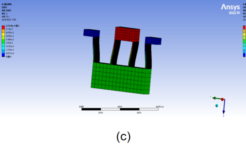
Figure 9: Deformation Results of the Double-Parallel Quadrilateral Flexible Mechanism Finite Element Analysis
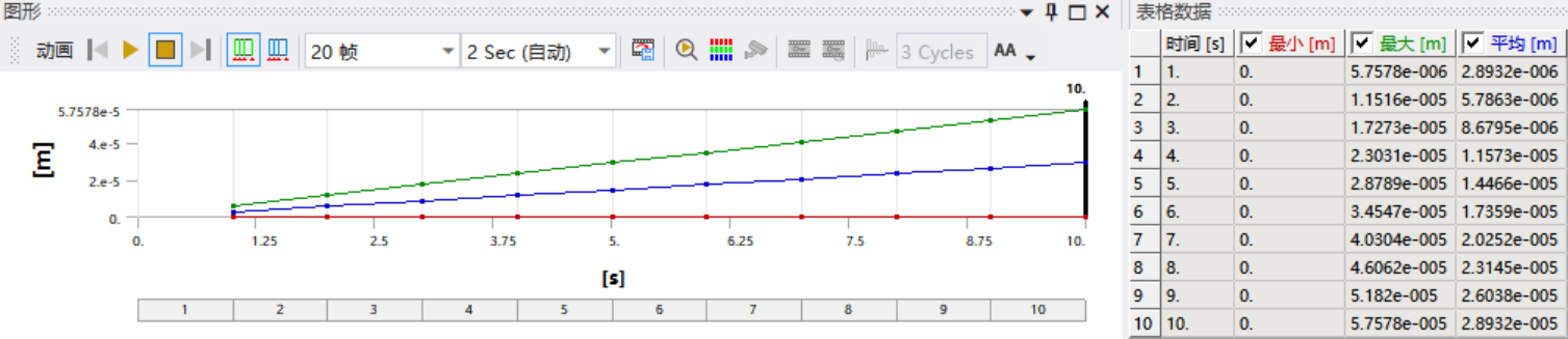
Figure 10: Data Results of the Double-Parallel Quadrilateral Flexible Mechanism Finite Element Analysis
The theoretical stiffness calculation results are obtained by substituting the dimensions into Equation (5), as shown in Equation (10):
\( {K_{3}} \) = \( \frac{{Ebh^{3}}}{{l^{3}}} \) =1.775× \( {10^{5}} \) N/m (10)
Based on the simulation results, the stiffness is calculated as shown in Equation (11):
\( {K \prime _{3}} \) = \( \frac{1}{5.7578×{10^{-6}}} \) N/m=1.737× \( {10^{5}} \) N/m (11)
The deviation between the theoretical stiffness and the simulation stiffness of the double-parallel quadrilateral flexible mechanism is 2.1%.
3.4. Mirrored Double Parallel Workpiece
The mirrored double-parallel flexible mechanism (as shown in Figure 11) has beam dimensions of 1 mm*20 mm*20 mm. The UG model is imported into the ANSYS engineering simulation software, where the material is set as aluminum, and its hardness and elastic modulus are defined. A Cartesian coordinate system is established [8]-[10]. The model is meshed with a grid size of 0.5 mm*0.5 mm, with the right side designated as the support surface. Force is applied perpendicularly inward, ranging from 1 N to 10 N, divided into ten steps with a 1 N increment per step. Finally, the stiffness values are calculated, and the finite element analysis curve is generated.
The deformation results from the finite element analysis of the mirrored double-parallel quadrilateral flexible mechanism are shown in Figure 11, while the data results are shown in Figure 12.
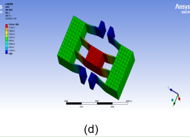
Figure 11: Deformation Results of the Mirrored Double-Parallel Quadrilateral Flexible Mechanism Finite Element Analysis
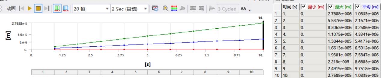
Figure 12: Data Results of the Mirrored Double-Parallel Quadrilateral Flexible Mechanism Finite Element Analysis
The theoretical stiffness calculation results are obtained by substituting the dimensions into Equation (5), as shown in Equation (12):
\( {K_{4}} \) = \( \frac{{2Ebh^{3}}}{{l^{3}}} \) =3.55× \( {10^{5}} \) N/m (12)
Based on the simulation results, the stiffness is calculated as shown in Equation (13):
\( {K \prime _{4}} \) = \( \frac{1}{2.7688×{10^{-6}}} \) N/m=3.612× \( {10^{5}} \) N/m (13)
The deviation between the theoretical stiffness and the simulation stiffness of the mirrored double-parallel quadrilateral flexible mechanism is 1.7%.
4. Conclusion
In this study, the mechanical analysis and stiffness model of a double-parallel quadrilateral flexible mechanism were first established. Subsequently, stiffness models were developed for single-parallel quadrilateral, mirrored single-parallel quadrilateral, double-parallel quadrilateral, and mirrored double-parallel flexible mechanisms based on the serial-parallel combinations of flexible mechanisms. To verify the stiffness models of the four types of flexible mechanisms, three-dimensional models were built using UG and finite element analysis was conducted using ANSYS software. The deviations between the theoretical stiffness and simulation stiffness for the respective mechanisms are as follows:
Single-parallel quadrilateral flexible mechanism: 1.9%
Mirrored single-parallel quadrilateral flexible mechanism: 3.5%
Double-parallel quadrilateral flexible mechanism: 2.1%
Mirrored double-parallel quadrilateral flexible mechanism: 1.7%
The results of the finite element analysis validate the accuracy of the established stiffness models, laying a foundation for the design of flexible mechanisms.
References
[1]. Teo, T. J., Chen, I.-M., Yang, G., & Lin, W. (2008). A flexure-based electromagnetic linear actuator. Nanotechnology, 19(31), 315501.
[2]. Ding, X., & Dai, J. S. (2010). Compliance analysis of mechanisms with spatial continuous compliance in the context of screw theory and Lie groups. Proceedings of the Institution of Mechanical Engineers, Part C: Journal of Mechanical Engineering Science, 224(11), 2493–2504.
[3]. Choi, J., Hong, S., Lee, W., Kang, S., & Kim, M. (2011). A robot joint with variable stiffness using leaf springs. IEEE Transactions on Robotics, 27(2), 229–238.
[4]. DiBiasio, C. M., Culpepper, M. L., Panas, R., Howell, L. L., & Magleby, S. P. (2008). Comparison of molecular simulation and pseudo-rigid-body model predictions for a carbon nanotube-based compliant parallel-guiding mechanism. Journal of Mechanical Design, 130(4), 042308.
[5]. Liaw, H. C., Shirinzadeh, B., & Smith, J. (2008). Sliding-mode enhanced adaptive motion tracking control of piezoelectric actuation systems for micro/nano manipulation. IEEE Transactions on Control Systems Technology, 16(4), 826–833.
[6]. Li, Y., & Xu, Q. (2011). A novel piezoactuated XY stage with parallel, decoupled, and stacked flexure structure for micro-/nanopositioning. IEEE Transactions on Industrial Electronics, 58(8), 3601–3615.
[7]. Krohs, F., Onal, C., Sitti, M., & Fatikow, S. (2009). Towards automated nanoassembly with the atomic force microscope: A versatile drift compensation procedure. Journal of Dynamic Systems, Measurement, and Control, 131(6), 061106.
[8]. Leang, K. K., Zou, Q., & Devasia, S. (2009). Feedforward control of piezoactuators in atomic force microscope systems: Inversion-based compensation for dynamics and hysteresis. IEEE Control Systems Magazine, 29(1), 70–82.
[9]. Yong, Y. K., Aphale, S., & Moheimani, S. O. R. (2009). Design, identification, and control of a flexure-based XY stage for fast nanoscale positioning. IEEE Transactions on Nanotechnology, 8(1), 46–54.
[10]. Polit, S., & Dong, J. (2011). Development of a high-bandwidth XY nanopositioning stage for high-rate micro-/nanomanufacturing. IEEE/ASME Transactions on Mechatronics, 16(4), 724–733.
Cite this article
Liu,H. (2025). Design Analysis and Verification of Leaf Spring-Based Compliant Mechanisms. Applied and Computational Engineering,143,8-17.
Data availability
The datasets used and/or analyzed during the current study will be available from the authors upon reasonable request.
Disclaimer/Publisher's Note
The statements, opinions and data contained in all publications are solely those of the individual author(s) and contributor(s) and not of EWA Publishing and/or the editor(s). EWA Publishing and/or the editor(s) disclaim responsibility for any injury to people or property resulting from any ideas, methods, instructions or products referred to in the content.
About volume
Volume title: Proceedings of the 3rd International Conference on Functional Materials and Civil Engineering
© 2024 by the author(s). Licensee EWA Publishing, Oxford, UK. This article is an open access article distributed under the terms and
conditions of the Creative Commons Attribution (CC BY) license. Authors who
publish this series agree to the following terms:
1. Authors retain copyright and grant the series right of first publication with the work simultaneously licensed under a Creative Commons
Attribution License that allows others to share the work with an acknowledgment of the work's authorship and initial publication in this
series.
2. Authors are able to enter into separate, additional contractual arrangements for the non-exclusive distribution of the series's published
version of the work (e.g., post it to an institutional repository or publish it in a book), with an acknowledgment of its initial
publication in this series.
3. Authors are permitted and encouraged to post their work online (e.g., in institutional repositories or on their website) prior to and
during the submission process, as it can lead to productive exchanges, as well as earlier and greater citation of published work (See
Open access policy for details).
References
[1]. Teo, T. J., Chen, I.-M., Yang, G., & Lin, W. (2008). A flexure-based electromagnetic linear actuator. Nanotechnology, 19(31), 315501.
[2]. Ding, X., & Dai, J. S. (2010). Compliance analysis of mechanisms with spatial continuous compliance in the context of screw theory and Lie groups. Proceedings of the Institution of Mechanical Engineers, Part C: Journal of Mechanical Engineering Science, 224(11), 2493–2504.
[3]. Choi, J., Hong, S., Lee, W., Kang, S., & Kim, M. (2011). A robot joint with variable stiffness using leaf springs. IEEE Transactions on Robotics, 27(2), 229–238.
[4]. DiBiasio, C. M., Culpepper, M. L., Panas, R., Howell, L. L., & Magleby, S. P. (2008). Comparison of molecular simulation and pseudo-rigid-body model predictions for a carbon nanotube-based compliant parallel-guiding mechanism. Journal of Mechanical Design, 130(4), 042308.
[5]. Liaw, H. C., Shirinzadeh, B., & Smith, J. (2008). Sliding-mode enhanced adaptive motion tracking control of piezoelectric actuation systems for micro/nano manipulation. IEEE Transactions on Control Systems Technology, 16(4), 826–833.
[6]. Li, Y., & Xu, Q. (2011). A novel piezoactuated XY stage with parallel, decoupled, and stacked flexure structure for micro-/nanopositioning. IEEE Transactions on Industrial Electronics, 58(8), 3601–3615.
[7]. Krohs, F., Onal, C., Sitti, M., & Fatikow, S. (2009). Towards automated nanoassembly with the atomic force microscope: A versatile drift compensation procedure. Journal of Dynamic Systems, Measurement, and Control, 131(6), 061106.
[8]. Leang, K. K., Zou, Q., & Devasia, S. (2009). Feedforward control of piezoactuators in atomic force microscope systems: Inversion-based compensation for dynamics and hysteresis. IEEE Control Systems Magazine, 29(1), 70–82.
[9]. Yong, Y. K., Aphale, S., & Moheimani, S. O. R. (2009). Design, identification, and control of a flexure-based XY stage for fast nanoscale positioning. IEEE Transactions on Nanotechnology, 8(1), 46–54.
[10]. Polit, S., & Dong, J. (2011). Development of a high-bandwidth XY nanopositioning stage for high-rate micro-/nanomanufacturing. IEEE/ASME Transactions on Mechatronics, 16(4), 724–733.