


1. Introduction
This article thoroughly investigates the performance of robotic systems operating under low Reynolds number conditions, where viscous forces are more significant than inertial forces. In such scenarios, fluid dynamics at the microscopic scale display characteristics that differ markedly from those at the macroscopic scale. According to the scallop theorem [1], mutual motion cannot result in net displacement. This necessitates innovative designs for micro-robots to overcome viscous resistance effectively.
Micro-robots have significant potential for various applications, especially in the biomedical field [2]. For instance, this micro-robotic can navigate blood vessels and other bodily fluids, facilitating targeted drug delivery to specific locations. This capability not only boosts therapeutic efficacy but also minimizes potential side effects associated with systemic treatments. Furthermore, micro-robots can fulfill crucial functions in real-time physiological monitoring, enabling the detection of early disease indicators, such as cancer or infections, and collecting biological samples for further analysis [3]. Despite the considerable potential of these technologies, the design and control of micro-robots encounter significant challenges when operating in low Reynolds number environments.
Extensive research has been dedicated to comprehending low Reynolds number fluid dynamics, particularly in biological organisms like bacteria and sperm, which exhibit effective locomotion strategies to traverse high-viscosity environments [4]. Inspired by these movement patterns, this article aims to design a biomimetic micro-robot that integrates flagellar propulsion mechanisms, emulating the natural motion of these organisms. Using a computational model, this research examines the dynamic performance of the proposed robotic design in viscous fluids [5]. The results of this investigation are intended to offer a solid theoretical framework and practical insights that can enhance the energy efficiency and motion control of micro-robots in low Reynolds number conditions [6].
2. Theoretical framework
2.1. Calculation example
In Figure 1, an explicit situation is shown for calculating a microorganism's biggest velocity with the change of the pitch angle of its tail.
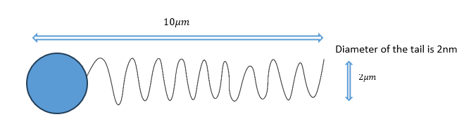
Figure 1: explicit situation of a microorganism
2.2. Calculating bacterial motion
Table 1: Parameters necessary for calculating bacterial motion
Symbol | parameter | value |
\( {μ_{0}} \) | Viscosity of water at 25°C in Pa·s | 0.89e-3 |
\( L \) | Length of flagellar filament in meters | 10e-6 |
\( r \) | Radius of flagellar helix in meters | 20e-9 |
\( p \) | Pitch of flagellar helix in meters | 2e-6 |
\( {w_{f}} \) | Flagellar rotation rate in rad/s (200 Hz) | 2*pi*200 |
\( a \) | Cell width / 2 in meters | 1e-6 |
\( b \) | Cell length / 2 in meters | 1e-6 |
\( d \) | Diameter of the flagellar helix | 2 * r |
\( {α_{c}},{β_{c}} \) | Drag coefficients of cell body | |
\( {α_{f}},{β_{f}},{γ_{f }} \) | Drag coefficients of cell body | |
\( {v_{N}},{v_{T}} \) | velocities in the normal and tangential directions | |
\( {dF_{N}},{dF_{T}} \) | Hydrodynamic forces acting on ds in the normal and tangential directions |
In the following stages, the final velocities will be calculated in the normal and tangential directions step by step. The parameters used for calculating bacterial motion are listed in Table 1. The first step is about calculating the Drag coefficients of the cell body [7]:
Assuming that the shape of a cell body is a spheroid, the drag coefficients, α_c, and β_c, are formulated by viscosity and cell shape in traditional low-Reynolds-number hydrodynamics. So in a polymer solution, the viscosity, μ, in α_c should be modified to μ_N^*,μ_T^* in each direction (but the value should be the same), a virtual space around the cell body moves as the cell body moves translationally, and the virtual space doesn’t move when the cell body rotates. Therefore the equations are written below.
\( {α_{c}}=-6πμ_{N}^{*}a\lbrace 1-\frac{1}{5}(1-\frac{b}{a})\rbrace \) | (1) |
\( {β_{c}}=-6πμ_{T}^{*}a\lbrace 1-\frac{1}{5}(1-\frac{b}{a})\rbrace \) | (2) |
Then, assuming that the shape of a flagellum is a helical thin filament, the drag coefficients,α_(f),β_(f,) γ_(f) are given as follows in the traditional RFT [8]
\( {α_{f}}=\frac{2πμL}{(log{[d/2p]}+1/2)(4{π^{2}}{r^{2}}+{p^{2}})×(8{π^{2}}{r^{2}}+{p^{2}})} \) | (3) |
\( {β_{f}}=\frac{2πμL}{(log{[d/2p]}+1/2)(4{π^{2}}{r^{2}}+{p^{2}})×(4{π^{2}}{r^{2}}+{2p^{2}}){r^{2}}} \) | (4) |
\( {γ_{f}}=\frac{2πμL}{(log{[d/2p]}+1/2)(4{π^{2}}{r^{2}}+{p^{2}})×(-2π{r^{2}}p)} \) | (5) |
The next step is to note that the actual motor torque has been reported to remain approximately constant up to a specific knee rotation rate. Beyond this point, it decreases gradually with increasing rotation rate, as documented in sources [9,10], and [11]. It is assumed that the motor torque decreases linearly with the motor rotation rate, especially since the motor in a free-swimming cell typically operates above this knee rotation rate.
The simultaneous equations from 6 to 10 were analytically resolved as follows:
\( {K_{0}}=-(\frac{{ω_{f}}}{{α_{c}}{β_{c}}+{α_{f}}{β_{c}}}) \) | (6) |
\( v={K_{0}}{β_{c}}{γ_{f}} \) | (7) |
Subsequent to that, calculating the value of v_N,v_T, which can be expressed by using v and ω_fas shown below:
\( tan{[θ]}=\frac{p}{2πr} \) | (8) |
\( {v_{N}}=vcos{[θ]-r{ω_{f}}sin{[θ]}} \) | (9) |
\( {v_{T}}=vsin{[θ]+r{ω_{f}}cos{[θ]}} \) | (10) |
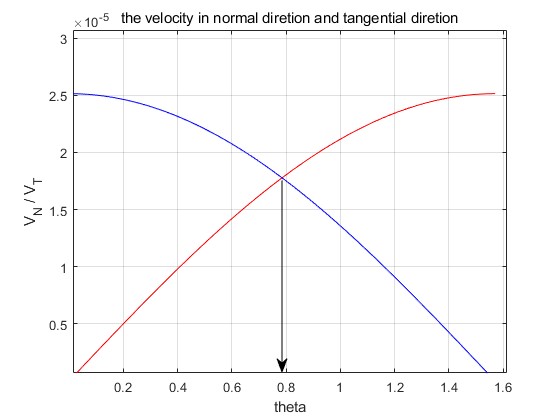
Figure 2: The bacterium achieves its highest speed when the angle is 45 degrees.
Equipped with the final velocities in each direction, a figure aimed at determining the angle at which the bacterium achieves its highest speed is created by MATLAB, and the specific code will be shown in the Appendix. According to Figure 2, when theta is equal to (√2)/2≈0.71, then the velocity is the biggest one. So the theta of the flagellum should be 45 degrees in the following design and experiments, which shows maximum propulsion efficiency for bacterial flagellum with similar configurations under low Reynolds conditions.
2.3. Simulation and modeling
The simulated prototype in SolidWorks is shown in Figure 3. The plan is to make the flagella tilt at a 45-degree Angle, mimicking the shape of sperm [12].
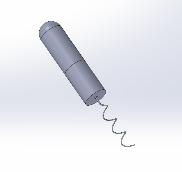
Figure 3: Simulation prototypes on SolidWorks
2.4. The explanation of the design and limitations
This section outlines the design choices for the robot. Its shape enables efficient spiral propulsion in low Reynolds number environments, where viscous forces dominate and fluid resistance is significant. Similar to how bacteria generate thrust with their rotating flagella, the spiral structure effectively propels fluid through rotation, allowing for stable motion. The cylindrical body minimizes fluid separation and disturbances, promoting smooth flow while reducing drag. Furthermore, the inclusion of a spiral tail enhances thrust in viscous fluids. This design is particularly well-suited for microfluidic and biomedical applications, facilitating precise operations in blood, viscous solutions, or microtubes.
However, aiming to apply it in biomedical and microfluidic fields, there are some limitations remaining as I mentioned in the discussion and conclusion. The following contents ignore the non-Newtonian effects and simplify the detailed energy analysis. What’s more, the robust error analysis is simplified as well.
3. Experiment setup
After all the stages above, the robot prototype is printed out by the 3D printer, aiming to test its dynamic performance in different liquids. And at the same time, simulation of its dynamic performance will be tested in MATLAB.
3.1. Dynamic simulation
Using the code provided in Appendix 2, we can observe the ideal relationship in Figure 4 between the velocity and the rotation speed of the flagellum in water.
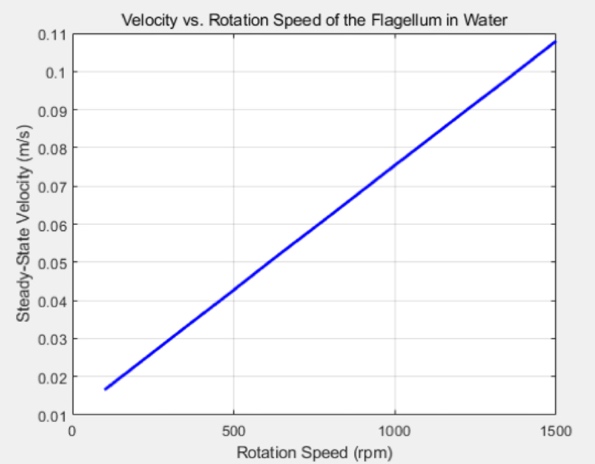
Figure 4: The ideal relationship between the velocity and rotational speed
3.2. Simulation in water
Secondly, here is the prototype, which is hundreds of times bigger than the tiny robot.
|
|
Figure 5: Beginning | Figure 6: Ending |
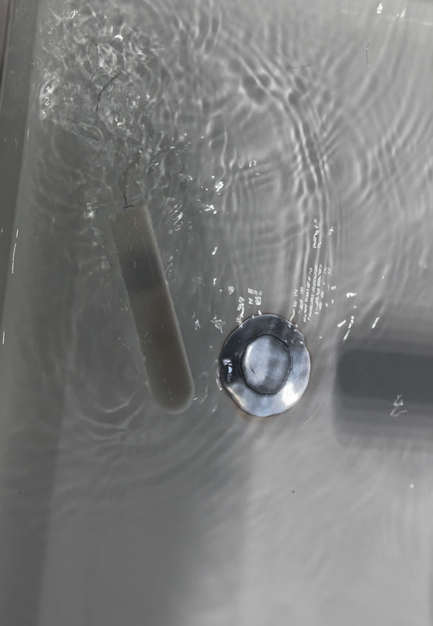
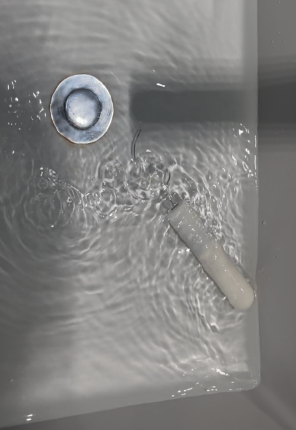
The first picture is T1 and the second picture is T2, and I will document the distance the robot ran during the time. Then, we can calculate the velocity by the following equation:
\( V=\frac{D}{{T_{2}}-{T_{1}}} \) | (11) |
After that, adjust the engine's rotation rate to investigate whether the velocity and rotation speed meet the aforementioned expectation. Here is the average of the three experiments :
Table 2: the experimental results
Rotation speed(rpm) | Time beginning (s) | Time end (s) | Distance (m) | Velocity (m/s) |
300 | 0 | 2.84 | 0.34 | 0.12 |
600 | 0 | 1.27 | 0.33 | 0.26 |
900 | 0 | 0.87 | 0.37 | 0.43 |
1200 | 0 | 0.54 | 0.29 | 0.57 |
1500 | 0 | 0.47 | 0.34 | 0.72 |
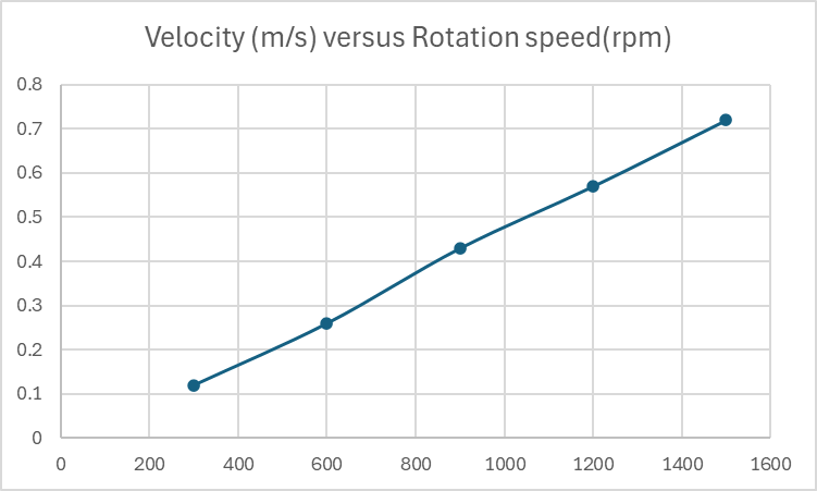
Figure 7: The experimental results
The comparable results between the ideal situation simulated in MATLAB and the experimental data indicate that this type of robot can achieve good energy efficiency and optimised motion in viscous fluids for biomedical and microfluidic applications. The experimental results in Figure 7 show a strong correlation between rotational speed and velocity, aligning with the MATLAB simulations in Figure 4. However, deviations at higher speeds(e.g., 1500 rpm) suggest potential nonlinear effects, such as increased turbulence or motor inefficiency, which were not accounted for in the idealised model.
4. Discussion and conclusion
Based on bionic design and theoretical analysis, this paper proposes a microrobot suitable for a low Reynolds number environment. Its movement mechanism is based on the flagellar propulsion principle of bacteria and sperm. Combined with computational fluid dynamics models and experimental verification, this study reveals the key role of non-reciprocal motion modes in viscosity-dominated environments. The theoretical derivation shows that when the inclination Angle of the flagellar spiral structure is 45 degrees, the robot can obtain the maximum propulsion speed (about 0.72 m/s), which is highly consistent with the MATLAB simulation results (the speed increases linearly with the speed under ideal conditions). Experimental data further validate the design's high energy utilization in Newtonian fluids, where the steady-state velocity is positively correlated with the rotation rate (up to 0.72 m/s at 1500 rpm), confirming the advantages of the helical structure in overcoming viscous resistance. Moreover, the 45-degree helical angle shown in Figure 2 maximizes propulsion efficiency, which is critical for biomedical applications with stringent energy constraints. On this basis, future designs could explore adaptive angles to handle varying fluid viscosities.
However, this study still has some limitations: the complex rheological properties of non-Newtonian fluids are not considered, the energy dissipation model is simplified, and the experimental prototype size is different from the actual micron-scale robot. Future work needs to further explore the stability of motion in non-uniform flow fields, multi-physical coupling effects (such as electromagnetic drive and fluid interaction), and optimization of miniaturized manufacturing processes. Beyond that, real-world biomedical fluids (e.g., blood [13]) exhibit shear-thing behavior, which may significantly alter propulsion dynamics. Addressing this requires incorporating viscoelastic fluid models in future studies. The results of this study provide a theoretical basis and technical reference for the applications of biomedical targeted drug delivery, microfluidic manipulation, and in vivo diagnosis, as well as promote the practical process of microrobot design in a low Reynolds number environment.
5. Appendix
5.1. Code 1
% Given constants and parameters
mu_0 = 0.89e-3; % Viscosity of water at 25°C in Pa·s
L = 10e-6; % Length of flagellar filament in meters
r = 20e-9; % Radius of flagellar helix in meters
p = 2e-6; % Pitch of flagellar helix in meters
omega_f =2*pi*200; % Flagellar rotation rate in rad/s (200 Hz)
a = 1e-6; % Cell width / 2 in meters
b = 1e-6; % Cell length / 2 in meters
d = 2 * r; % Diameter of the flagellar helix
theta = linspace(0,pi/2,400); %helical angle of flageller helix;
% Corrected equations from the paper
alpha_c = -6 * pi * mu_0 * a * (1 - (1/5) * (1 - (a/b)));
beta_c = -8 * pi * mu_0 * a^3 * (1 - (3/5) * (1 - (a/b)));
alpha_f = 2 * pi * mu_0 * L / (log(d/(2*p)) + 0.5) * (4 * pi^2 * r^2 + p^2) * (8 * pi^2 * r^2 + (mu_0/mu_0) * p^2);
beta_f = 2 * pi * mu_0 * L / (log(d/(2*p)) + 0.5) * (4 * pi^2 * r^2 + p^2) * (2 * p^2 + (mu_0/mu_0) * 4 * pi^2 * r^2) * r^2;
gamma_f = 2 * pi * mu_0 * L / (log(d/(2*p)) + 0.5) * (4 * pi^2 * r^2 + p^2) * (2 - (mu_0/mu_0)) * (-2 * pi * r^2 * p);
% Calculation of K0, v, and omega_c, V_N and V_T;
K0 = -omega_f/((alpha_c * beta_c)+(alpha_f * beta_c));
v = K0 * beta_c * gamma_f;
V_N = abs(v*cos(theta)-r*omega_f*sin(theta));
V_T = v*sin(theta)+r*omega_f*cos(theta);
% Display the calculated speeds
figure;% creates a new figure window
plot(theta,V_N,'r');
title('the velocity in normal diretion and tangential diretion');
hold on;
plot(theta,V_T,'b');
xlabel('theta');
ylabel('V_N / V_T');
5.2. Code 2
% Parameters
R_head = 0.012; % Head radius (m)
R_body = 0.012; % Body radius (m)
L_body = 0.11; % Body length (m)
L_tail = 0.1; % Tail length (m)
slope = 45; % Helix slope (degrees)
R_helix = 0.01; % Helix radius (m)
% Fluid properties
rho = 1000; % Water density (kg/m^3)
% Drag coefficients
Cd_head = 0.47; % Approximate drag coefficient for a hemisphere
Cd_body = 1.2; % Approximate drag coefficient for a cylinder
% Cross-sectional areas
A_head = pi * R_head^2; % Cross-sectional area of the head (m^2)
A_body = 2 * R_body * L_body; % Cross-sectional area of the body (m^2)
% Range of rotational rates
rpm_range = 100:50:1500; % Rotation speed range (rpm)
velocities = zeros(size(rpm_range)); % To store calculated velocities
% Loop over each rotational rate
for j = 1:length(rpm_range)
rpm = rpm_range(j); % Current rotational rate
omega = rpm * 2 * pi / 60; % Convert rpm to rad/s
% Calculate propulsive force (simplified model)
F_prop = 2 * pi * R_helix * omega * L_tail; % Propulsive force in N (arbitrary units)
% Initial guess for velocity (m/s)
v = 0.01;
% Iteratively solve for the velocity where F_prop = F_drag
for i = 1:1000
% Drag forces
F_drag_head = 0.5 * Cd_head * rho * v^2 * A_head;
F_drag_body = 0.5 * Cd_body * rho * v^2 * A_body;
% Total drag force
F_drag_total = F_drag_head + F_drag_body;
% Net force (should be zero at steady state)
F_net = F_prop - F_drag_total;
% Adjust velocity based on net force (simple iterative approach)
v = v + 0.0001 * F_net; % Adjust velocity towards balance
end
% Store the calculated velocity
velocities(j) = v;
end
% Plotting the results
figure;
plot(rpm_range, velocities, 'b-', 'LineWidth', 2);
xlabel('Rotation Rate (rpm)');
ylabel('Steady-State Velocity (m/s)');
title('Velocity vs. Rotation Rate of the Flagellum in Water');
grid on;
References
[1]. Hubert M, et al. 2021. Scallop theorem and swimming at the mesoscale. Phys Rev Lett. 126(22):224501. doi: 10.1103/PhysRevLett.126.224501
[2]. Purcell, E. M. (1977), "Life at low reynolds number", American Journal of Physics, 45 (1): 3–11, Bibcode:1977AmJPh..45....3P, doi:10.1119/1.10903, hdl:2433/226838
[3]. Berg, H. C. 2000. Constraints on models for flagellar rotary motor. Phil.Trans. R. Soc. Lond. B. 355:491–501.
[4]. Holwill, M. E. J., and R. E. Burge. 1963. A hydrodynamic study of the motility of flagellated bacteria. Arch. Biochem. Biophys. 101:249 –260.
[5]. Magariyama, Y., S. Sugiyama, K. Muramoto, I. Kawagishi, Y. Imae, and S. Kudo. 1995. Simultaneous measurement of bacterial flagellar rotation rate and swimming speed. Biophys. J. 69:2154 –2162.
[6]. Derr NJ, Dombrowski T, Rycroft CH, Klotsa D. 2022. Reciprocal swimming at intermediate Reynolds number. J Fluid Mech. 952:A8. doi: 10.1017/jfm.2022.873
[7]. Berg, H. C. 2000. Constraints on models for flagellar rotary motor. Phil. Trans. R. Soc. Lond. B. 355:491–501.
[8]. Ryu, W. S., R. M. Berry, and H. C. Berg. 2000. Torque-generating units of the flagellar motor of Escherichia coli have a high duty ratio. Nature.403:444 – 447.
[9]. Chen, X., and H. C. Berg. 2000. Torque-speed relationship of the flagellar
[10]. Berg HC & Anderson RA (1973). "Bacteria swim by rotating their flagellar filaments". Nature. 245 (5425): 380–382. Bibcode:1973Natur.245..380B. doi:10.1038/245380a0. PMID 4593496. S2CID 4173914
[11]. Silverman M & Simon M (1974). "Flagellar rotation and the mechanism of bacterial motility". Nature. 249 (100): 73–74. Bibcode:1974Natur.249...73S. doi:10.1038/249073a0. PMID 4598030. S2CID 10370084
[12]. Jahanshaloo L, Sidik NAC, Fazeli A, Pesaran H A M.(2016). An overview of boundary implementation in lattice Boltzmann method for computational heat and mass transfer. Int Commun Heat Mass Tran. 78:1–12.
[13]. Pandey, R., & Yadav, P. K. (2022). Effect of Reynolds number and blood viscosity models on the left coronary artery with multiple stenoses. Physics of Fluids, 34(9), 091903. https://doi.org/10.1063/5.0099822
Cite this article
Zhang,Y. (2025). Biomimetic Design an Performance Analysis of Micro-Robot in Low Reynolds Number Environments. Applied and Computational Engineering,147,40-48.
Data availability
The datasets used and/or analyzed during the current study will be available from the authors upon reasonable request.
Disclaimer/Publisher's Note
The statements, opinions and data contained in all publications are solely those of the individual author(s) and contributor(s) and not of EWA Publishing and/or the editor(s). EWA Publishing and/or the editor(s) disclaim responsibility for any injury to people or property resulting from any ideas, methods, instructions or products referred to in the content.
About volume
Volume title: Proceedings of the 3rd International Conference on Mechatronics and Smart Systems
© 2024 by the author(s). Licensee EWA Publishing, Oxford, UK. This article is an open access article distributed under the terms and
conditions of the Creative Commons Attribution (CC BY) license. Authors who
publish this series agree to the following terms:
1. Authors retain copyright and grant the series right of first publication with the work simultaneously licensed under a Creative Commons
Attribution License that allows others to share the work with an acknowledgment of the work's authorship and initial publication in this
series.
2. Authors are able to enter into separate, additional contractual arrangements for the non-exclusive distribution of the series's published
version of the work (e.g., post it to an institutional repository or publish it in a book), with an acknowledgment of its initial
publication in this series.
3. Authors are permitted and encouraged to post their work online (e.g., in institutional repositories or on their website) prior to and
during the submission process, as it can lead to productive exchanges, as well as earlier and greater citation of published work (See
Open access policy for details).
References
[1]. Hubert M, et al. 2021. Scallop theorem and swimming at the mesoscale. Phys Rev Lett. 126(22):224501. doi: 10.1103/PhysRevLett.126.224501
[2]. Purcell, E. M. (1977), "Life at low reynolds number", American Journal of Physics, 45 (1): 3–11, Bibcode:1977AmJPh..45....3P, doi:10.1119/1.10903, hdl:2433/226838
[3]. Berg, H. C. 2000. Constraints on models for flagellar rotary motor. Phil.Trans. R. Soc. Lond. B. 355:491–501.
[4]. Holwill, M. E. J., and R. E. Burge. 1963. A hydrodynamic study of the motility of flagellated bacteria. Arch. Biochem. Biophys. 101:249 –260.
[5]. Magariyama, Y., S. Sugiyama, K. Muramoto, I. Kawagishi, Y. Imae, and S. Kudo. 1995. Simultaneous measurement of bacterial flagellar rotation rate and swimming speed. Biophys. J. 69:2154 –2162.
[6]. Derr NJ, Dombrowski T, Rycroft CH, Klotsa D. 2022. Reciprocal swimming at intermediate Reynolds number. J Fluid Mech. 952:A8. doi: 10.1017/jfm.2022.873
[7]. Berg, H. C. 2000. Constraints on models for flagellar rotary motor. Phil. Trans. R. Soc. Lond. B. 355:491–501.
[8]. Ryu, W. S., R. M. Berry, and H. C. Berg. 2000. Torque-generating units of the flagellar motor of Escherichia coli have a high duty ratio. Nature.403:444 – 447.
[9]. Chen, X., and H. C. Berg. 2000. Torque-speed relationship of the flagellar
[10]. Berg HC & Anderson RA (1973). "Bacteria swim by rotating their flagellar filaments". Nature. 245 (5425): 380–382. Bibcode:1973Natur.245..380B. doi:10.1038/245380a0. PMID 4593496. S2CID 4173914
[11]. Silverman M & Simon M (1974). "Flagellar rotation and the mechanism of bacterial motility". Nature. 249 (100): 73–74. Bibcode:1974Natur.249...73S. doi:10.1038/249073a0. PMID 4598030. S2CID 10370084
[12]. Jahanshaloo L, Sidik NAC, Fazeli A, Pesaran H A M.(2016). An overview of boundary implementation in lattice Boltzmann method for computational heat and mass transfer. Int Commun Heat Mass Tran. 78:1–12.
[13]. Pandey, R., & Yadav, P. K. (2022). Effect of Reynolds number and blood viscosity models on the left coronary artery with multiple stenoses. Physics of Fluids, 34(9), 091903. https://doi.org/10.1063/5.0099822