


1. Introduction
At present, there are four main types of aero-engines: turbojet engine, gas turbine fan engine, gas turbine shaft engine and gas turbine propeller engine. Our research focuses on the thrust-to-weight ratio and energy efficiency. At the same time, the invention of turbojet engine marks the development of engine from piston type to jet type. At present, turbo engine is still one of the most commonly used engines in aerospace, aerospace and ships. A turbocharged engine is an air compressor that uses the exhaust gas from a turbo engine as its power to drive the turbine located in the exhaust pipe. When the turbine rotates, it drives the coaxial impeller located in the intake duct, compresses the fresh air in the air filter tube and feeds it into the cylinder. With the increase of air compression, the intake volume of the engine increases accordingly, the combustion in the cylinder is more complete and the power output is higher. At the same time, as the engine speed increases, high-speed exhaust gas will drive the turbine speed to increase, and the exhaust emission speed and turbine speed will also accelerate simultaneously. However, its obvious disadvantage is that due to material limitations, gas combustion is incomplete and fuel consumption is high.
In terms of power source, turbo-jet engine mainly uses compressor and compressor to provide power. However, with the continuous development of aerospace industry, the requirements and requirements for engine power of various military and civil aircraft are increasing, which puts forward new requirements for Aeroengine design. However, the high thrust of aircraft is always only in the temporary state of starting, climbing, emergency maneuver and so on. In order to solve this situation, the engine put forward the concept of “rear force”. Performance characteristics of both naturally aspirated and turbo engines.
2. Turbine Engine Power System
2.1. Working Principle of Engine
2.1.1. Engine Structure Composition. In this article, part of the turbojet engine is shown. In this case, this article is interested in what happens to the air passing through the engine. A large amount of ambient air is continuously brought into the engine inlet. A tubular entrance is shown here, as seen on an airliner. Figure 1 shows the structure of the engine.
|
Fig. 1. Engine structure diagram [1]. |
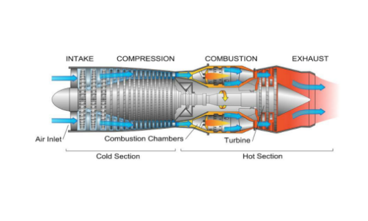
However, the shape and size of the intake ports depend on the load and thrust ratio required by the aircraft. Compressors are like rows of wings, each producing a small pressure leap. A compressor is like an electric fan. Energy must be provided to turn the compressor. At the bottom of the intake port, air enters the compressor. At the outlet of the compressor, the pressure of air is much higher than that of free flow. Turbines extract energy from the air stream by rotating blades in the air stream [2]. In a burner, a small amount of fuel combines with air and is ignited. Leaving the burner, hot exhaust gas passes through the turbine. Most of the time, turbines work like windmills. For jet engines, the energy extracted from the turbine is used to turn the compressor, which is connected to the turbine through a central shaft. Turbines absorb some energy from high-temperature exhaust gases, but the remaining energy is transferred through the nozzles to increase speed and provide thrust for the jet engine [2].
2.1.2. Type of Turbine Engine. Depending on the classification, turbine engines can be classified into many different types. For example, if the positions of combustor and rotor are distinguished, there are gas turbine engines belonging to the type of external gas turbine and turbofan engines belonging to the type of internal combustion engine.
In practice, a turbo engine will run in the opposite direction, turning it into an input power device for moving fluids, such as a compressor and a pump. Some turbo engines themselves have multiple sets of vanes, one that draws power from the fluid and the other that drives it. However, the functions of the two cannot be confused [3]. For example, in most turbo and turboprop engines, the actual function of the fan blades in front of the combustion chamber is to pressurize the intake air and should therefore be considered a compressor. The true turbine part is a fan located at the rear of the combustion chamber, powered by the exhaust gas generated after combustion. Energy eventually delivers power through the axial main fan blade (turbo engine) or the propeller (turbo engine) in the engine.
2.2. The Working Principle of Afterburner
Afterburner is a component that injection, ignition and combustion to the gas or the airflow behind the fan on the afterburner engine to increase the temperature of the airflow and increase the engine thrust in a short period of time. Afterburners are commonly used in the engines of supersonic aircraft, such as fighter jets [4].
The incoming flow in the afterburner is the exhaust of the main combustion chamber, resulting in the oxygen content of afterburner combustion is lower than that of the main combustion chamber, which puts forward a severe test to the combustion structure in the afterburner. In view of this problem, the relevant research mainly focuses on changing the structural parameters of the stabilizer, designing the integrated stabilizer, etc., and obtains relatively comprehensive and perfect research results.
At the same time, different inlet parameters and stabilizer structure will affect the performance parameters of afterburner. Currently, there are three performance testing methods.
1. The steady state parameters were simulated by numerical simulation method for different stabilizer Angle, different stabilizer width, different inlet air temperature and different fuel jet velocity [4].
2. A more comprehensive understanding of afterburner is obtained by combining steady-state numerical simulation with transient test [4].
3. A new ignition method of high temperature thermal jet which generates high temperature heat flow by injecting extra oil into the main combustion chamber to ignite the afterburner. The thermal jet ignition method with extra oil injection in the main combustion chamber can effectively ignite the afterburner to make it work normally, but the disadvantage is that the turbine needs to withstand instantaneous high temperature. Increasing the length of afterburner can effectively improve the combustion efficiency of afterburner and increase the thrust of engine [4].
2.3. Engine Application Status
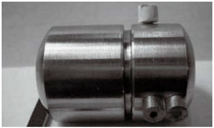
The most advanced microturbine engines are mostly used in the military field, and their parameters are a secret of each country's military development. At present, one of the most commonly used in military applications is as the driving force of missiles. The power of this micro turbine engine is usually large, mostly of 60 kg thrust, and the material quality and design structure are more perfect than the general micro turbine engine [5]. In the future military research, the micro-turbine engine should also be used for the flight of UAVs to provide continuous power [5].When it is applied to the field of UAV flight, the power of the engine itself has more strict requirements, and the research on the power needs to be further strengthened. Figure 2 is a schematic diagram of a micro turbine engine.
|
Fig. 2. Micro turbine engine [5]. |
Application of micro turbine engine on small locomotive The application of micro turbine engine in this field is mainly popular among some locomotive enthusiasts. Many people install micro turbine engine on their locomotive in order to pursue the speed of driving. The power of this kind of engine is usually relatively large, about dozens of kg level, the most basic power requirement is to significantly improve the speed of the locomotive.
3. Performance and Development Status of Aeroengine
3.1. Performance Comparison of Aeroengine
In order to analyze the performance characteristics of turbojet engine more intuitively, the difference between naturally aspirated engine and turbojet engine can be studied from the power of turbojet engine. Figure 3 shows the power comparison between the naturally aspirated engine and the turbojet engine.
|
Fig. 3. Power comparison between naturally aspirated engine and turbojet engine [6]. |
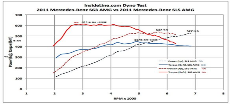
1. From the perspective of torque, the turbocharged engine has been greater than the natural intake engine from 2000 RPM to 6500 RPM. Until 6500 RPM and close torque. The turbocharged engine reaches maximum torque from 2500 RPM and continues to decrease until around 4500 RPM, while the natural intake engine reaches maximum torque from 4000 RPM to 6500 RPM. It can be seen that the maximum torque of the turbocharged engine appears at low RPM and transfer number, while the natural intake engine appears at transfer number to high RPM.
2. From the point of view of horsepower, since the turbocharged engine reaches the maximum torque from 2500 RPM, the horsepower is also increased faster, reaching the maximum horsepower at 4500 RPM, and basically maintaining the maximum horsepower from 4500 RPM to 6500 RPM. Look at natural intake horsepower engine basic maintain a straight line, the largest horsepower in maximum revolutions.
3.2. Current status of Industrial Development
The aircraft engine market includes turbo-powered engines such as turboprop and turbo-shaft engines, jet engines such as turbo-jet and turbo-fan engines, pulse jet engines, rocket and reciprocating engines, and many others. According to the 2009 CFM Aircraft Engine Market Report with 39% international market share [6], the most common aircraft engine, especially in commercial aircraft applications, is the turbofan engine. Figure 4 shows the trend of the engine market.
|
Fig. 4. Engine Market Change Trend Map [7]. |
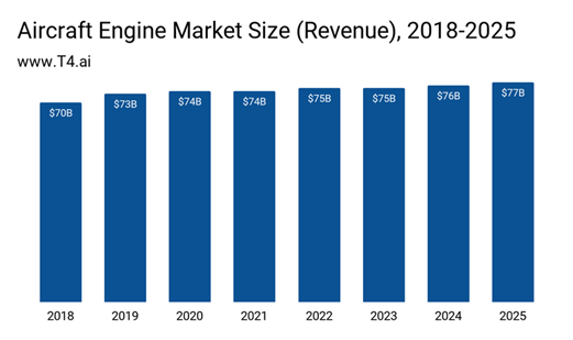
From an economic perspective, the engine market is a growing trend. According to statistics, the size of the aircraft engine industry is 73 billion US dollars in 2019 and is expected to grow by 0.8% by 2020 [6]. From 2018 to 2025, the aircraft engine industry is expected to grow by an average of 1% per year [6].The development of the aero-engine industry depends mainly on the performance of the new generation of engines and the demand of the transportation industry from the current global economic development. The increase of demand will promote the improvement of industrial manufacturing capacity. At the same time, the impact of the current world new crown pneumonia epidemic makes the reduction of aero-engine demand also bring about a considerable impact on the aerospace industry.
4. Future Direction can be Improved
As for plasma engine, it is a kind of electric propulsion system, which has been widely used at home and abroad, and its main application medium is plasma. Figure 5 shows the plasma engine model.
|
Fig. 5. Plasma engine model [8]. |
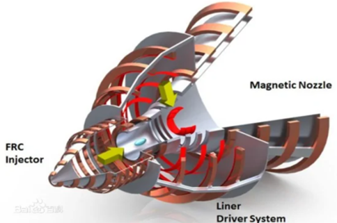
It uses Lorentz forces to accelerate charged atoms or ions through a magnetic field to drive spacecraft in reverse, in the same way particle accelerators and airguns work. Because of high power, high altitude performance. It is often used to power fighter jets [9].
At present, the biggest drawback of plasma engine is that the thrust-weight ratio is too small. Although the conventional rocket engine has a relatively high thrust weight, it consumes fuel at a very low specific impulse in a very short time. Today's ion engines can run for months or even years, so that while the thrust is small, it can be accumulated over a long period of time to achieve a higher total impulse [10].
5. Conclusion
In this paper, the structure and performance of the turbine engine and the combustion efficiency of the combustion chamber are discussed. The defects of the current engine and improved components were found. It is hoped that the combustion efficiency can be improved by changing the inlet structure design. The power and torque of turbine engine and natural intake engine are compared. The turbo engine has better thrust. Current afterburners will make turbocharged engines the power source for the next generation of supersonic fighters. The gas pressure in the combustion chamber is already very high and it may not be possible to increase the pressure any further. As there is no bypass in the turbo-jet engine, improving the turbine front temperature is the only way to improve the performance of the turbo-jet engine.
In this study, we found that for the combustion chamber, increasing the distribution density and atomization of the injector nozzle can achieve higher power at higher speeds. In terms of energy consumption, methods such as saving fuel, using biofuels, new energy, etc. can be used or better aerodynamic design and pneumatic layout can be used. Finally, the possible future plasma engines are discussed. Although the thrust-to-gravity ratio is the biggest problem of plasma engine at present, its efficient energy utilization and very low energy consumption are still worth studying.
References
[1]. Ando S. 1983 Current Status and Future of Intelligent Industrial Robots. Industrial Electronics IEEE Transactions on, 19: 81-83.
[2]. Yan D Y. 1985 Modelling the Axial-Flow Compressors for Calculating Starting of Turbojet Engines. Asme Beijing International Gas Turbine Symposium & Exposition. American Society of Mechanical Engineers, 30: 70-85.
[3]. Guillot-Salomon D, Potagnik N. 2005 Process and device for supplying the turbojets of an aircraft during automatic flight. Energies, 20: 205-211.
[4]. Hwang D, Wontae D. 2020 Fuel Stratification for Low-Load HCCI Combustion: Performance and Fuel-PLIF Measurements. 20: 107-109.
[5]. Peng A. 2007 Study the ethanol SI/HCCI combustion mode transition by using the fast thermal management system. Chinese Science Bulletin, 20: 109-116.
[6]. Kim H, Lee R K. 2007 A study on the characteristics of spray and combustion in a HCCI engine according to various injection angles and timings. Journal of Mechanical Science&Technology, 20: 207-218.
[7]. Bunce P. 2014 For 2013 large bizjets, turboprops and helicopters were up with smaller jet and piston models continuing to struggle. Professional Pilot, 48: 103-116.
[8]. Liu H, Zheng Z, Zhang B. 2009 Influence of fuel characteristics on combustion and operating range of HCCI engine. Journal of Internal Combustion Engine, 27 (3): 9.
[9]. Cullemore R. 2010 Regional jets and turboprops : the new Russian and Chinese products. Aviation Strategy, 10(158): 4-9.
[10]. Wang Y, Zhou L B, Jiang D M. 2002 Research Development and Main Challenge of Homogeneous Charge Compression Ignition(HCCI). Vehicle Engine, 20: 302-308.
Cite this article
Yu,M. (2023). Current status of turbojets and their future . Applied and Computational Engineering,5,475-480.
Data availability
The datasets used and/or analyzed during the current study will be available from the authors upon reasonable request.
Disclaimer/Publisher's Note
The statements, opinions and data contained in all publications are solely those of the individual author(s) and contributor(s) and not of EWA Publishing and/or the editor(s). EWA Publishing and/or the editor(s) disclaim responsibility for any injury to people or property resulting from any ideas, methods, instructions or products referred to in the content.
About volume
Volume title: Proceedings of the 3rd International Conference on Signal Processing and Machine Learning
© 2024 by the author(s). Licensee EWA Publishing, Oxford, UK. This article is an open access article distributed under the terms and
conditions of the Creative Commons Attribution (CC BY) license. Authors who
publish this series agree to the following terms:
1. Authors retain copyright and grant the series right of first publication with the work simultaneously licensed under a Creative Commons
Attribution License that allows others to share the work with an acknowledgment of the work's authorship and initial publication in this
series.
2. Authors are able to enter into separate, additional contractual arrangements for the non-exclusive distribution of the series's published
version of the work (e.g., post it to an institutional repository or publish it in a book), with an acknowledgment of its initial
publication in this series.
3. Authors are permitted and encouraged to post their work online (e.g., in institutional repositories or on their website) prior to and
during the submission process, as it can lead to productive exchanges, as well as earlier and greater citation of published work (See
Open access policy for details).
References
[1]. Ando S. 1983 Current Status and Future of Intelligent Industrial Robots. Industrial Electronics IEEE Transactions on, 19: 81-83.
[2]. Yan D Y. 1985 Modelling the Axial-Flow Compressors for Calculating Starting of Turbojet Engines. Asme Beijing International Gas Turbine Symposium & Exposition. American Society of Mechanical Engineers, 30: 70-85.
[3]. Guillot-Salomon D, Potagnik N. 2005 Process and device for supplying the turbojets of an aircraft during automatic flight. Energies, 20: 205-211.
[4]. Hwang D, Wontae D. 2020 Fuel Stratification for Low-Load HCCI Combustion: Performance and Fuel-PLIF Measurements. 20: 107-109.
[5]. Peng A. 2007 Study the ethanol SI/HCCI combustion mode transition by using the fast thermal management system. Chinese Science Bulletin, 20: 109-116.
[6]. Kim H, Lee R K. 2007 A study on the characteristics of spray and combustion in a HCCI engine according to various injection angles and timings. Journal of Mechanical Science&Technology, 20: 207-218.
[7]. Bunce P. 2014 For 2013 large bizjets, turboprops and helicopters were up with smaller jet and piston models continuing to struggle. Professional Pilot, 48: 103-116.
[8]. Liu H, Zheng Z, Zhang B. 2009 Influence of fuel characteristics on combustion and operating range of HCCI engine. Journal of Internal Combustion Engine, 27 (3): 9.
[9]. Cullemore R. 2010 Regional jets and turboprops : the new Russian and Chinese products. Aviation Strategy, 10(158): 4-9.
[10]. Wang Y, Zhou L B, Jiang D M. 2002 Research Development and Main Challenge of Homogeneous Charge Compression Ignition(HCCI). Vehicle Engine, 20: 302-308.