


1. Introduction
Since modern times, the world economy has developed rapidly, urban construction has been accelerating, and the demand for energy and resource extraction has gradually increased. To meet these development needs, construction machinery has also experienced rapid development. As a key specialized equipment in the fields of energy extraction and construction, the performance and reliability of engineering machinery have a decisive impact on engineering quality and construction efficiency. With the development of the times, the concepts of green mining and green construction have gradually entered the social vision, and environmental protection, energy conservation, and material saving are also one of the main development directions of future construction machinery. This article takes a small excavator as an example to study the optimization design of its boom, in order to reduce weight and save manufacturing materials while meeting safety requirements.
The boom is the core mechanical structural component of an excavator during excavation operations. The design of core mechanical structural components is crucial for excavators, as it directly affects the performance of excavator operations. However, it often leads to excessive design due to the emphasis on safety performance during operation, resulting in safety performance far exceeding established goals while significantly increasing the weight of the structure and the consumption of raw materials during manufacturing. At the same time, the larger weight also requires excavators to consume more energy during operation, which is not in line with the current theme of green development and mining. Therefore, many scientists have conducted optimization design research on the boom of excavators.
Chen et al. [1] took the boom of a hydraulic excavator as the research object, optimized the thickness of each welding plate through Isight software on the premise of meeting the strength requirements, and reduced the weight of the boom by 8%. Zhao et al. [2] took the secondary arm of an excavator as the research object, and used Altair inspire software to optimize its topology. After optimization, the quality of the model was reduced by 33.6%, and the strength and stiffness met the safety requirements. Wang et al. [3] took the boom of a medium-sized excavator as the research object. The boom structure is optimized through the results of ANSYS software static analysis, and the strength and stiffness of the optimized model are improved. Pang et al. [4] took the boom of a hydraulic excavator as the research object, optimized the structure of high stress zone and reduced the thickness of welded plate in low stress zone through the finite element analysis results. After optimization, the boom mass and stress are reduced. Wang et al. [5] used the theory of controllable mechanism to carry out the lightweight design of excavator boom. After optimization, the boom mass is reduced and the performance parameters are improved on the premise of strength safety. Ning et al. [6] took the excavator stick as the research object and optimized the design of the stick through discrete element and topology optimization methods. The optimized model can reduce the weight and maintain the original level of strength. Li et al. [7] took the stick as the research object and optimized the design of the stick through the topology optimization method. After optimization, the stiffness of the stick model increased by 6.58% and the volume decreased by 18.22%. Huang et al. [8] took the boom of an excavator as the research object, obtained its stress distribution and modal shape through finite element analysis, and optimized the boom structure based on this, and the optimized structure met the safety requirements. Jiang et al. [9] took the boom of an excavator as the research object. Under the condition of meeting the stiffness and strength, the weight of the boom was reduced by 21.7% through the lightweight optimization method. Xiang et al. [10] took the boom of an excavator as the research object, and verified its lightweight model through the artificial neural network model. The results show that it is feasible to reduce the weight of the boom by the lightweight method. Bezkorovayny et al. [11] developed a method to determine the parameters of excavator working device based on mass and limit criteria, which can be used to determine the section size of boom and stick and the placement position of hydraulic cylinder. Yang et al. [12] constructed the optimization design coding system of the boom by using knowledge expression and coding processing technology, which realized the automatic optimization design of the boom, accelerated the optimization calculation speed and improved the optimization quality. Mohammad et al. [13] took an excavator stick as the research object and obtained the uncertain load acting on the stick by Monte Carlo method. The optimization results show that the weight of the stick obtained by this method is smaller and the stress value is lower. Sumar et al. [14] took the excavator arm as the research object and proposed a lightweight design scheme that still retains its strength. When the excavator arm meets the safety requirements, the mass is reduced from 4000kg to 3852kg.
Based on the analysis of the research status of the structural optimization design of the excavator working device, it can be seen that experts and scholars have conducted a lot of research on the excavator working device, used a variety of different methods to optimize the excavator boom, and achieved fruitful results. Therefore, this paper will take a small hydraulic excavator as an example, use the method of topology optimization and response surface optimization to optimize its boom, and put forward a complete set of excavator boom optimization process. Compared with the single use of topology optimization, it is easier to obtain the optimization model, which can be used as a reference for the optimization of other working devices of the excavator.
2. Force analysis of excavator boom
In this paper, the boom of the small excavator is the integral bending boom. The advantages of the integral boom are simple structure, light weight and high stiffness. Its disadvantage is that it has few working devices to replace, and its versatility is poor. It is mostly used on excavators with similar long-term operating conditions. The three dimensional model is shown in Figure 1.
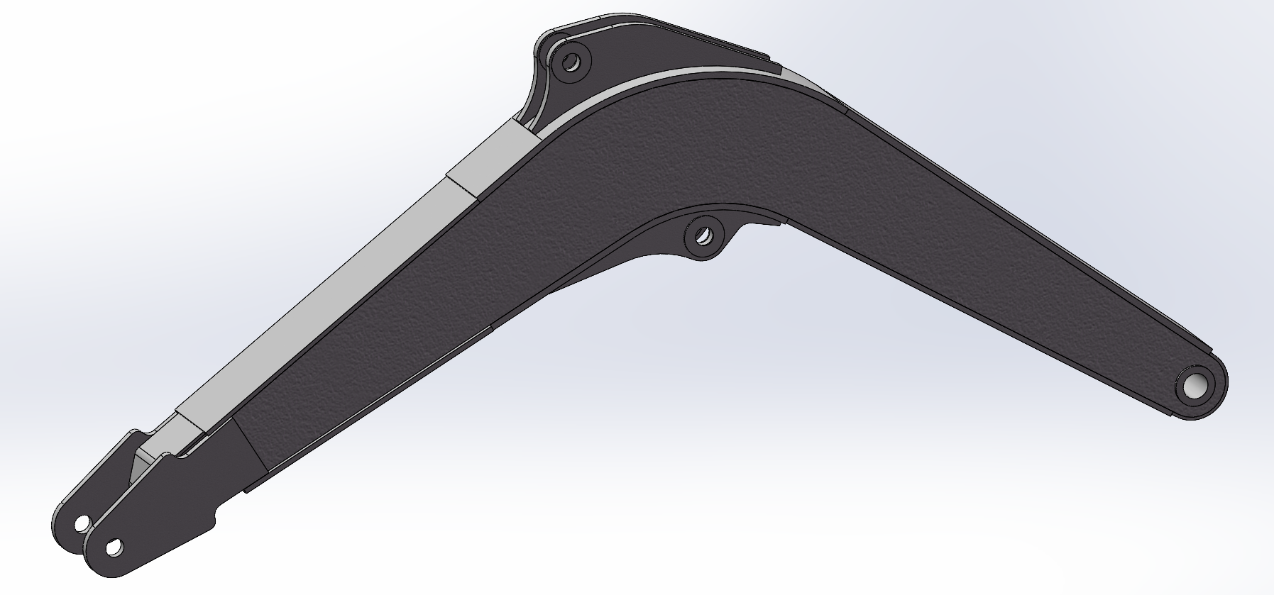
Figure 1: Three dimensional diagram of excavator boom
The typical excavation conditions of excavator excavation operation are divided into bucket excavation, stick excavation and compound excavation. Based on these three conditions, this paper will analyze the force of excavator boom under three conditions. Before analysis, it is necessary to name each hinge point and establish the X-Y axis coordinate system of the excavator, as shown in Figure 2.
Figure 2: Coordinate system regulations for excavators
In the mechanical analysis of the boom, the first thing is to establish its force analysis model. The boom is connected to other components through four hinge points F, I, H and J. the interaction forces borne by these hinge points are located in the X-Y plane and can be characterized by their components in the X and Y directions. When carrying out finite element simulation and structural optimization of the boom, only the force conditions of its connection point F with the stick and the hinge point H with the stick cylinder need to be considered. Based on this simplification principle, the forces at F and H points on the boom can be derived from the interaction relationship between components after calculating the forces at F and G points on the stick. After the stress analysis, the stress results of each articulated point of the boom under three working conditions are shown in Table 1.
Table 1: The force distribution at each hinge point of the boom
Excavation conditions | Direction | F (kN) | H (kN) |
Bucket excavation | X | -250 | 203 |
Y | -187 | 183 | |
Z | 0 | 0 | |
Stick excavation | X | -165 | 141 |
Y | -110 | 113 | |
Z | 0 | 0 | |
Compound excavation | X | -278 | 297 |
Y | -172 | 160 | |
Z | 0 | 0 |
3. Finite element static analysis of excavator boom
Taking the three dimensional model of the boom as the basis of the finite element analysis model, the finite element model of the boom obtained by importing the model established by SolidWorks into Ansys Workbench is shown in Figure 3.
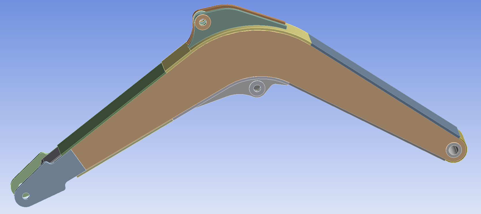
Figure 3: Finite element model of the boom
The materials used in the structural design of excavators are usually high-strength alloy plates of different specifications or precision cast steel parts. Set the default value in the Ansys Workbench material library according to its material parameters. The material data interface after setting is shown in Figure 4.
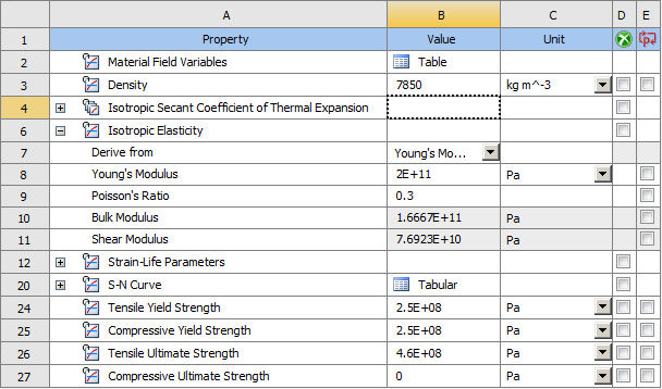
Figure 4: Material data setting diagram
In the process of mesh generation, the default mesh size is set to 5mm, and sparse meshes can be used in non critical parts to reduce the computational pressure of simulation operation. Proper control of grid density can make the simulation efficient while maintaining accuracy. The mesh division of the boom is shown in Figure 5.
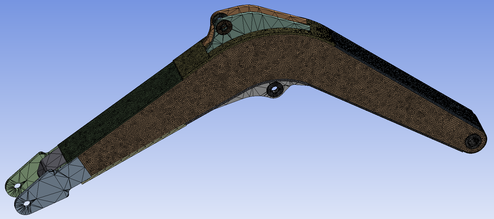
Figure 5: Boom network division diagram
The finite element simulation analysis is based on the modeling coordinate system of the model, while the stress analysis is based on the coordinate system with the gravity direction as the Y-axis. In order to ensure the consistency of the coordinate system during the simulation, the stress analysis results in the previous chapter need to be converted to the modeling coordinate system, and the transformed stress results are shown in Table 2.
Table 2: Force of each hinge point of the boom in modeling coordinate system
Excavation conditions | Point | X direction (kN) | Y direction (kN) | Z direction (kN) |
Bucket excavation | F | -296 | -99 | 0 |
H | 250 | 110 | 0 | |
Stick excavation | F | -191 | -52 | 0 |
H | 169 | 63 | 0 | |
Compound excavation | F | -302 | -125 | 0 |
H | 319 | 110 | 0 |
The working devices of excavators have large mass characteristics. In the process of finite element static analysis, it is necessary to decompose the gravity vector in X-axis and Y-axis. The effect of gravity field can be accurately simulated by applying acceleration which is opposite to the direction of gravity field and equal in size. The acceleration simulation of gravity in the modeling coordinate system under various working conditions is shown in Table 3.
Table 3: Gravity acceleration simulation value
Excavation conditions | Bucket excavation | Stick excavation | Compound excavation | |
Gravitational acceleration | Gx | 3092 | 3092 | 1569 |
Gy | 9306 | 9306 | 9680 | |
In the finite element analysis of the boom, the motion characteristics of the boom should be simulated first, and appropriate constraints should be imposed on the key nodes to ensure the accuracy of the motion behavior. For the boom structure, it is hinged to the body of the excavator and hinged to the boom hydraulic cylinder. These two places will not produce displacement, but will rotate around the hinge. Therefore, set its X, Y, Z, Rot X, Rot Y to 0, and its Rot Z to Free.
After adding materials, meshing, applying loads and constraints to the model, the finite model can be solved, and the stress nephogram and displacement nephogram of the boom model under three working conditions can be obtained.
(1) The stress nephogram and displacement nephogram of the boom under bucket excavation conditions are shown in Figure 6 and Figure 7.
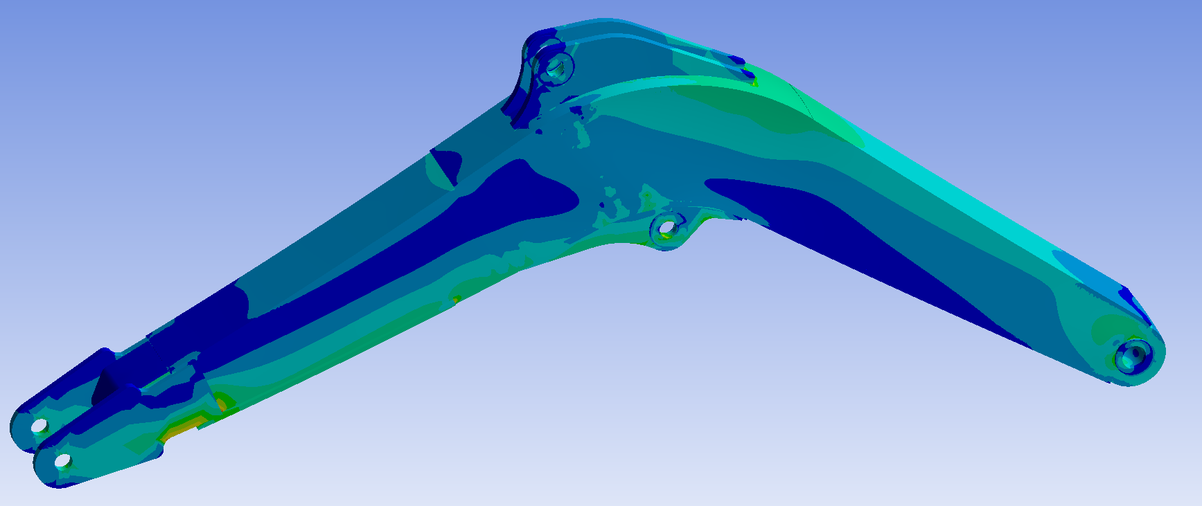
Figure 6: Stress nephogram of bucket excavation boom
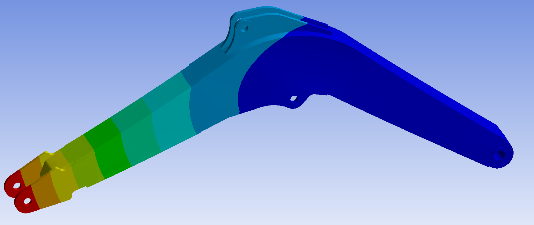
Figure 7: Displacement nephogram of bucket excavation boom
From Figure 6, it can be seen that the maximum stress on the boom is 197.56 MPa, located near the stick. Two low stress zones have appeared at the belly plate of the boom, which can be used as reference positions for optimization. From Figure 7, it can be seen that the maximum displacement is 5.9138 mm, located at the hinge between the boom and the stick.
(2) The stress nephogram and displacement nephogram of the boom under stick excavation conditions are shown in Figure 8 and Figure 9.
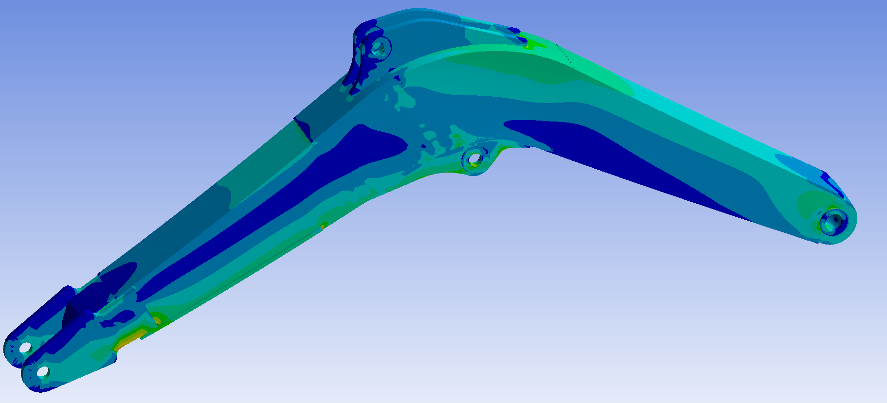
Figure 8: Stress nephogram of stick excavation boom
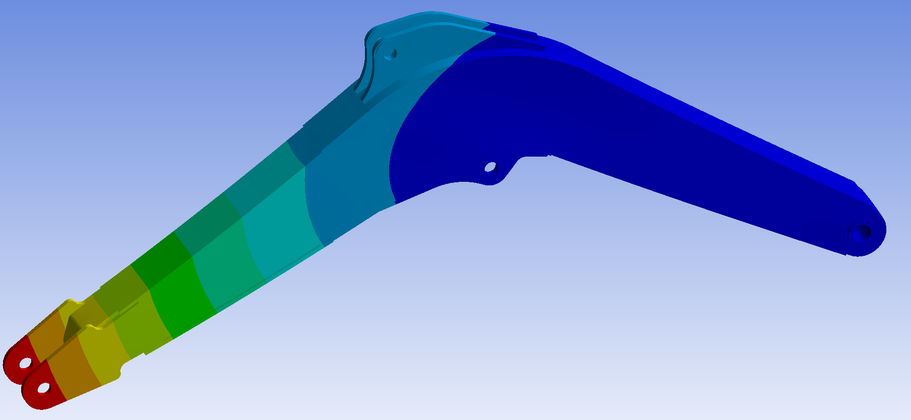
Figure 9: Displacement nephogram of stick excavation boom
From Figure 8, it can be seen that the maximum stress on the boom is 142.82 MPa, located near the stick. Two low stress zones have appeared at the belly plate of the boom, which can be used as reference positions for optimization. From Figure 9, it can be seen that the maximum displacement is 4.6828 mm, located at the hinge between the boom and the stick.
(3) The stress nephogram and displacement nephogram of the boom under compound excavation conditions are shown in Figure 10 and Figure 11.
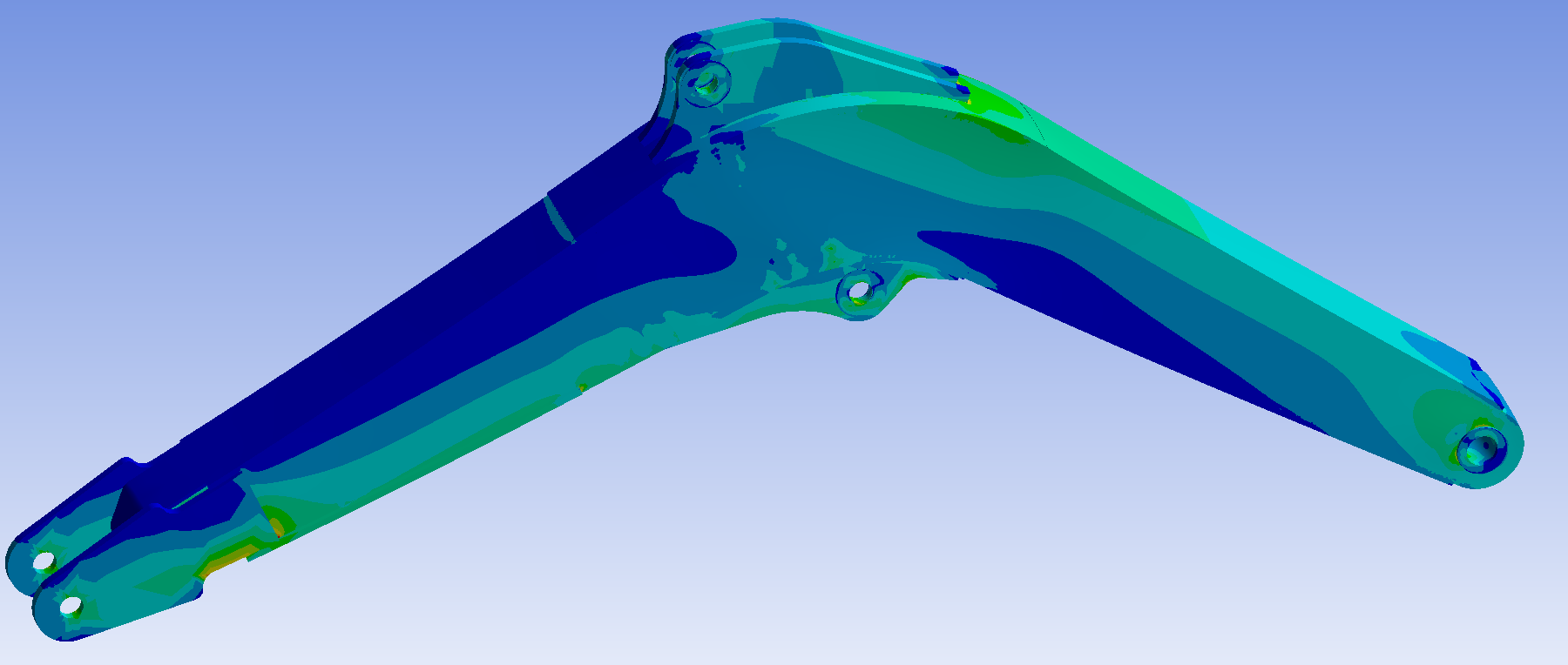
Figure 10: Stress nephogram of compound excavation boom
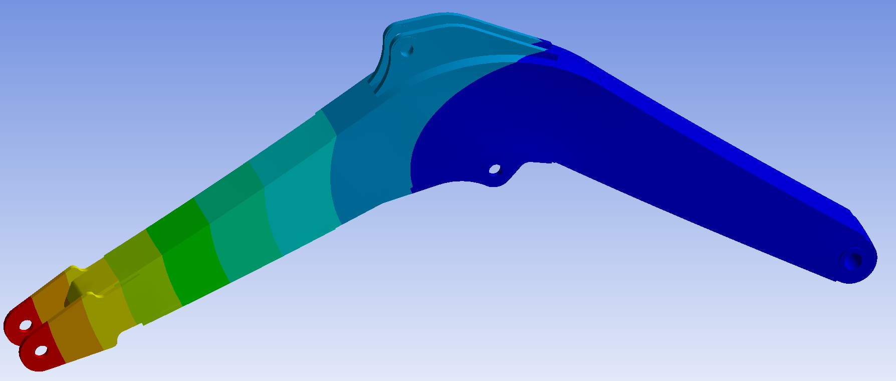
Figure 11: Displacement nephogram of compound excavation boom
From Figure 10, it can be seen that the maximum stress on the boom is 170.43 MPa, located near the stick. Two low stress zones have appeared at the belly plate of the boom, which can be used as reference positions for optimization. From Figure 11, it can be seen that the maximum displacement is 4.7345 mm, located at the hinge between the boom and the stick.
From the results of finite element analysis, it can be seen that the maximum stress of the boom under the three working conditions is 197.56 MPa under the bucket excavation condition, and the maximum displacement is 5.9138 mm under the bucket excavation condition. According to the material properties of the boom, its yield strength can be determined to be 345 MPa. Because this article ignored the effects of bias and friction on the force analysis of the boom, a safety factor of 1.4 was selected. The allowable stress of the boom under this safety factor is 246.42 MPa, which is greater than the maximum stress under various working conditions. It is concluded that the structure meets the strength requirements. Because the excavator boom is a large-sized component, the maximum displacement values under various working conditions are much smaller than the overall size of the structure, so the structure meets safety requirements.
4. Optimization of excavator boom structure and dimensions
4.1. Topology optimization of the boom structure
Choose Ansys Workbench as the platform for optimizing the structure of the boom mechanism, establish a coupling optimization framework for the boom static simulation A module and topology optimization B module as shown in Figure 12, and use this optimization framework to solve the topology optimization results.
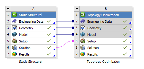
Figure 12: Coupling optimization framework
Topology optimization must clearly define the feasible region for optimization, which allows for material reduction and structural volume reduction operations. However, key areas in the structure, such as load-bearing surfaces, assembly holes, and load-bearing surfaces, usually need to maintain their integrity and are therefore not included in the optimization candidate range. Therefore, the optimization area for the boom is specified as shown in Figure 13.
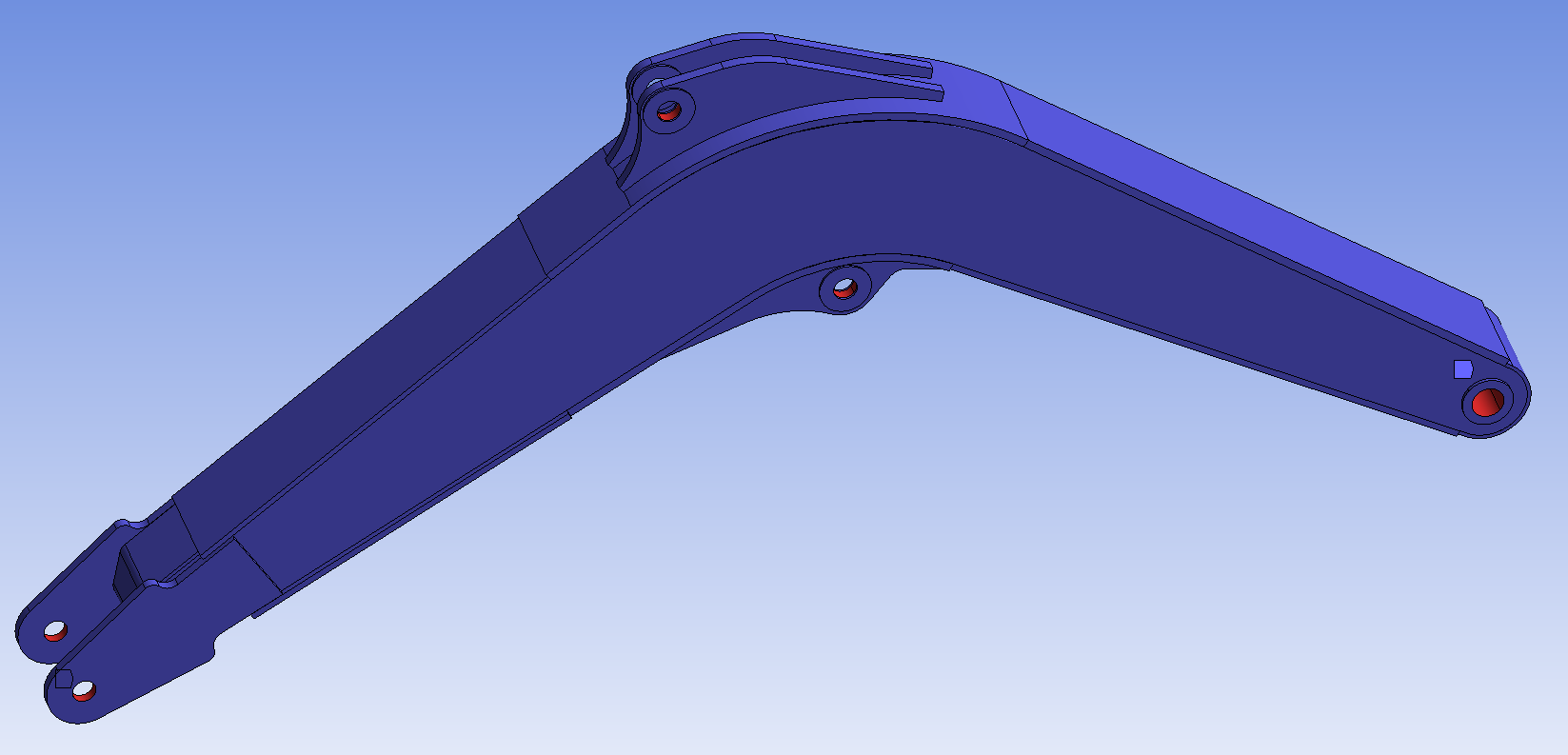
Figure 13: Optimization area of the boom
Set the number of iterations to 300, convergence accuracy to 0.1%, and quality retention to 80%, and perform iterative calculations. When solving, the working condition corresponding to the maximum stress of the boom is selected to obtain the topology optimization model of the boom as shown in Figure 14.
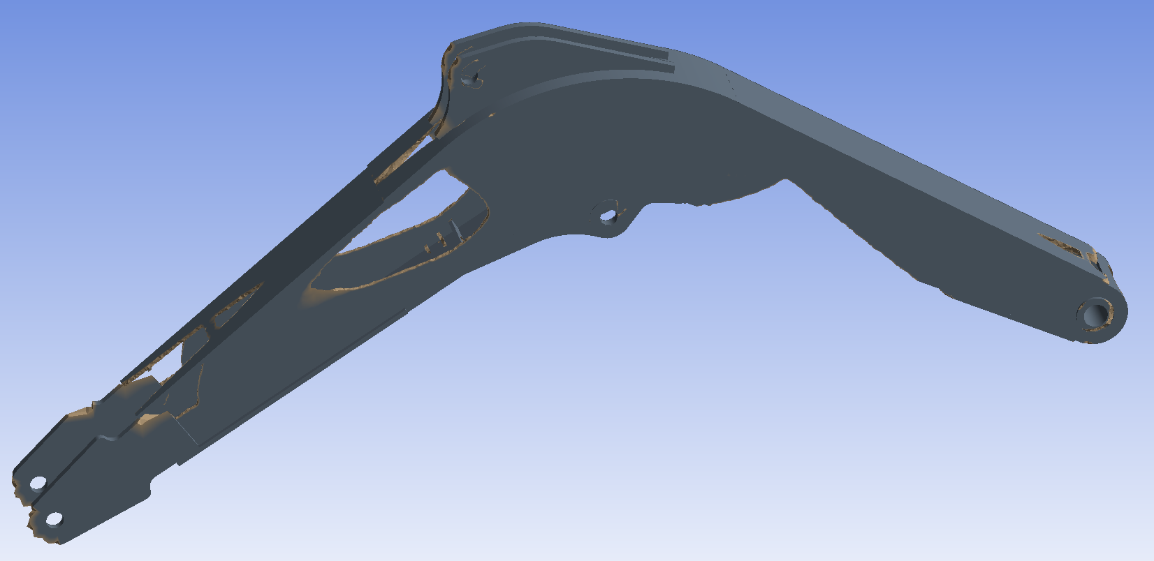
Figure 14: Results of the topology optimization model for the boom
According to the topology optimization model results of the boom shown in Figure 14, the boom optimization diagram is determined as shown in Figure 15.
Figure 15: Schematic diagram of the boom resection model
In Figure 15, the cut portion is the lower area of the upper ear plate, which is a quasi right angled triangle area. The lengths of the two right angled sides are e and f, respectively, and the length side of f is parallel to the front upper wing plate of the boom.
4.2. Optimization of response surface for the boom size
The response surface methodology describes the relationship between variables by constructing a mathematical model, typically represented by polynomial equations. This method can continuously analyze various levels of experiments and obtain more reasonable and reliable results. This article uses a second-order polynomial model to fit the response surface.
When establishing the mathematical model of the boom, the lengths e and f of the two right angled edges in the cutting area in Figure 15, the thickness g of the boom web, the thickness h of the front section of the upper wing plate, the thickness i of the rear section of the upper wing plate, the thickness j of the front section of the lower wing plate, and the thickness k of the rear section of the lower wing plate are selected as independent variables. The range of size changes of the boom is based on the size range optimized by topology, and a seven factor three-level orthogonal simulation experiment code is set as shown in Table 4.
Table 4: Factors and levels of the boom test
Factors | Levels | ||
1 | 2 | 3 | |
e (mm) | 110 | 165 | 220 |
f (mm) | 380 | 490 | 600 |
g (mm) | 7 | 10 | 13 |
h (mm) | 6 | 9 | 12 |
i (mm) | 8 | 13 | 18 |
j (mm) | 6 | 10 | 14 |
k (mm) | 6 | 10 | 14 |
Add the experimental factors and levels in Table 4 to the analysis software to generate a statistical table of response surface test results. Obtain the equivalent stress and mass results through finite element static analysis, and fill the results into the table. The results are shown in Table 5.
Table 5: Statistics of response surface test results for the boom
Number | e (mm) | f (mm) | g (mm) | h (mm) | i (mm) | j (mm) | k (mm) | P (MPa) | M (kg) |
1 | 220 | 380 | 10 | 6 | 13 | 10 | 10 | 257.98 | 362.69 |
2 | 165 | 380 | 7 | 9 | 13 | 14 | 10 | 255.57 | 339.6 |
3 | 165 | 490 | 10 | 9 | 13 | 10 | 10 | 247.43 | 367.28 |
4 | 220 | 490 | 10 | 9 | 13 | 6 | 6 | 337.67 | 350.46 |
5 | 165 | 490 | 10 | 6 | 8 | 14 | 10 | 261.92 | 357.58 |
... | |||||||||
55 | 165 | 490 | 7 | 12 | 13 | 10 | 6 | 305.13 | 328.46 |
56 | 165 | 490 | 7 | 6 | 13 | 10 | 14 | 311.33 | 335.94 |
57 | 165 | 490 | 10 | 9 | 13 | 10 | 10 | 247.43 | 367.28 |
58 | 220 | 490 | 7 | 9 | 18 | 10 | 10 | 307.94 | 341.39 |
59 | 165 | 600 | 10 | 9 | 18 | 10 | 6 | 250.92 | 367.48 |
Construct a linear regression model between response variables and multiple factors based on simulation experiment data using the analysis module. The results of the variance analysis of the mass and equivalent stress of the boom are shown in Tables 6 and 7.
Table 6: Analysis of variance of the boom mass
Source | Sum of squares | Free degree | Mean square error | F | P | |
Model | 35728.62 | 35 | 1020.82 | 2.254E+08 | < 0.0001 | significant |
e | 131.79 | 1 | 131.79 | 2.910E+07 | < 0.0001 | |
f | 105.50 | 1 | 105.50 | 2.330E+07 | < 0.0001 | |
g | 29522.63 | 1 | 29522.63 | 6.519E+09 | < 0.0001 | |
… | ||||||
h2 | 7.500E-06 | 1 | 7.500E-06 | 1.66 | 0.2109 | |
i2 | 0.0000 | 1 | 0.0000 | 5.07 | 0.0342 | |
j2 | 0.0000 | 1 | 0.0000 | 5.07 | 0.0342 | |
k2 | 0.0000 | 1 | 0.0000 | 10.35 | 0.0038 | |
Table 7: Analysis of variance of the boom equivalent stress
Source | Sum of squares | Free degree | Mean square error | F | P | |
Model | 1.361E+05 | 35 | 3887.50 | 35.74 | < 0.0001 | significant |
e | 2474.98 | 1 | 2474.98 | 22.75 | < 0.0001 | |
f | 194.31 | 1 | 194.31 | 1.79 | 0.1945 | |
g | 54341.12 | 1 | 54341.12 | 499.55 | < 0.0001 | |
… | ||||||
h2 | 70.15 | 1 | 70.15 | 0.6448 | 0.4302 | |
i2 | 852.31 | 1 | 852.31 | 7.84 | 0.0102 | |
j2 | 1900.85 | 1 | 1900.85 | 17.47 | 0.0004 | |
k2 | 3.51 | 1 | 3.51 | 0.0322 | 0.8591 | |
As shown in Table 6 and Table 7, the evaluation of the mass model and equivalent stress model of the boom is significant, so the construction of the model is correct. The simulation item with P value < 0.05 in the figure is an important simulation item, which has a more significant impact on the results than the rest.
When using Design-Expert software to carry out multiple linear regression analysis on the boom, according to the generated response surface regression model and based on the simulation test data, the mathematical regression equation between the boom stress and mass and its various factors can be obtained. At the same time, the residual normal distribution of equivalent stress and mass of the boom is also generated, as shown in Figures 16 and 17.
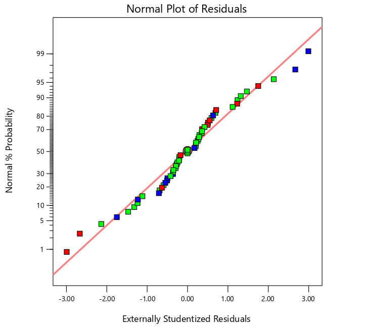
Figure 16: Normal distribution of residual equivalent stress of the boom
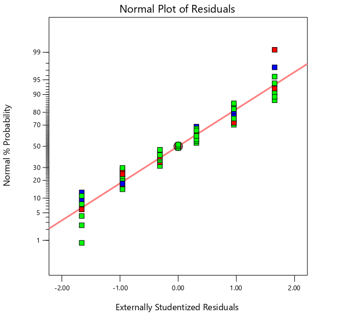
Figure 17: Normal distribution of residual mass of the boom
The linear distribution characteristics of the normal distribution of residuals can be used as an important index to evaluate the fitting degree of response surface model. It can be seen from Figures 16 and 17 that the residual data points of the boom show a good linear distribution trend, which fully shows that the established response surface model of the boom mass and equivalent stress has high fitting accuracy. Based on this, it can be considered that the calculation results of the regression equation have high reliability.
It can be concluded that the method of solving the optimal model parameters through the mathematical regression equation of the boom and obtaining the optimal parameter group is reasonable. In order to obtain the specific parameters of the optimized model, the Numerical module of Design-Expert software is used to solve the regression equation of the boom, and the optimal parameter solution of the boom can be calculated based on the objective function and constraints. The combination of optimal parameter solutions of the boom calculated by the mathematical regression model fitted by response surface software is shown in Table 8.
Objective function:
\( M=f(e,f,g,h,i,j,k)→min \) (1)
Constraint condition:
\( \begin{cases} \begin{array}{c} M≥0, 0≤P≤246 \\ 110≤e≤220, 380≤f≤600 \\ 7≤g≤13, 6≤h≤12 \\ 8≤i≤18, 6≤j≤14 \\ 6≤k≤14 \end{array} \end{cases} \) (2)
Table 8: Optimal parameter combination of the boom
Model | e (mm) | f (mm) | g (mm) | h (mm) | i (mm) | j (mm) | k (mm) | P (MPa) | M (kg) |
Before optimization | 0 | 0 | 10 | 12 | 18 | 14 | 14 | 197.56 | 407.6 |
After optimization | 144.3 | 600 | 7 | 6 | 14.9 | 13.9 | 6.1 | 244.7 | 328.4 |
Optimized proportion % | 19.31 | ||||||||
5. Model performance evaluation of excavator boom after optimization
Through the optimal design of the boom in the previous chapter, the optimal design model of the boom is obtained. In the actual excavation operation of excavator, the working device will inevitably hit objects with high hardness during excavation, and the boom will produce certain vibration. Therefore, the optimized boom model needs not only finite element static analysis and verification, but also modal analysis to analyze its vibration characteristics.
5.1. Finite element static analysis of the boom
Because in the previous analysis, the working condition with the maximum equivalent stress among the three working conditions was selected as the dangerous working condition, and this working condition was used as the basis for optimization. Therefore, when evaluating the performance of the optimized model, the previously selected hazardous conditions are still used as the evaluation basis. The obtained boom stress nephogram and displacement nephogram are shown in Figure 18 and Figure 19.
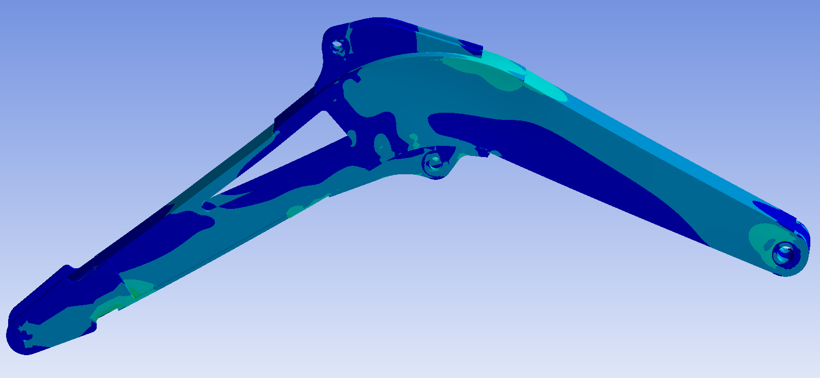
Figure 18: Stress nephogram of the boom
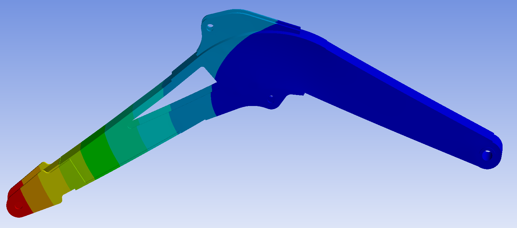
Figure 19: Displacement nephogram of the boom
According to Figures 18 and 19, the maximum stress value of the boom is located at the front of the boom, with a size of 387.2mpa, which is much larger than 246mpa under the safety factor. There is a problem here, so the image here is enlarged, as shown in Figure 20.
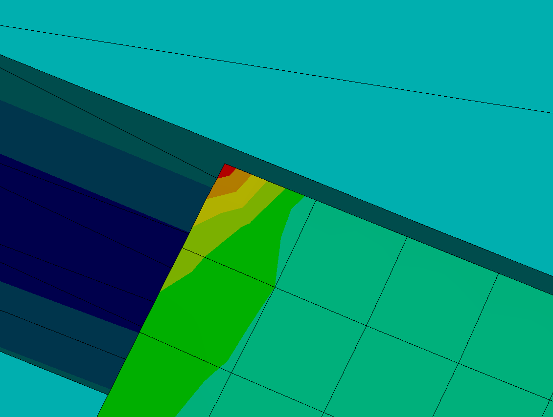
Figure 20: Location of maximum boom stress value
It can be seen from the figure that the area of maximum stress is very small, and the range is far less than one cell, and except here, the stress of the whole boom is in the normal range, so it is determined that there is a stress singularity during the simulation, which will not exist in reality, so it is excluded. The maximum displacement of the boom is at the hinge between the boom and the stick, and its value is 7.2793 mm, which meets the safety requirements. Therefore, the composite strength of the optimized boom model is required.
5.2. Modal analysis of the boom
Create a Modal module in Ansys Workbench, mesh the optimization model after importing the boom optimization model, and constrain the boom in order to simulate the impact. In the boom model, only Z-direction rotational degrees of freedom are reserved at the joints between the boom and the fuselage and between the boom cylinder and the boom, and the other five degrees of freedom are limited. No external load is set. The vibration mode diagrams as shown in Figures 21 to 26 are obtained.
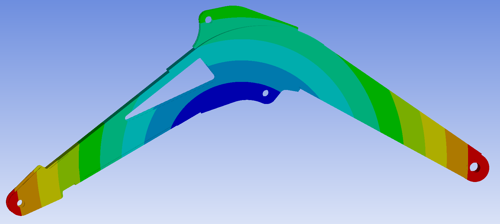
Figure 21: First order vibration mode of the boom
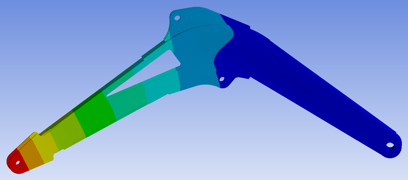
Figure 22: Second order vibration mode of the boom
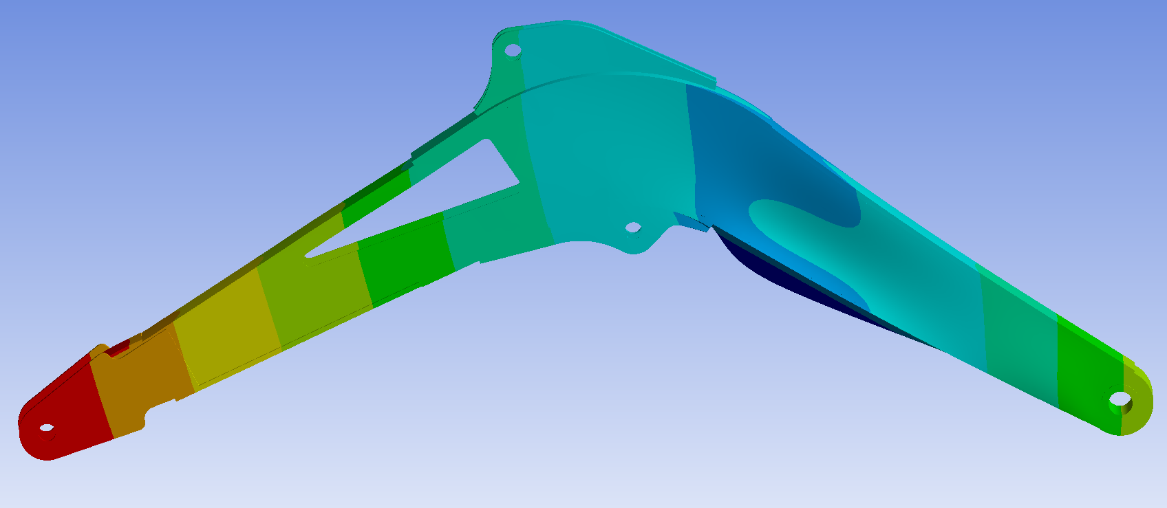
Figure 23: Third order vibration mode of the boom
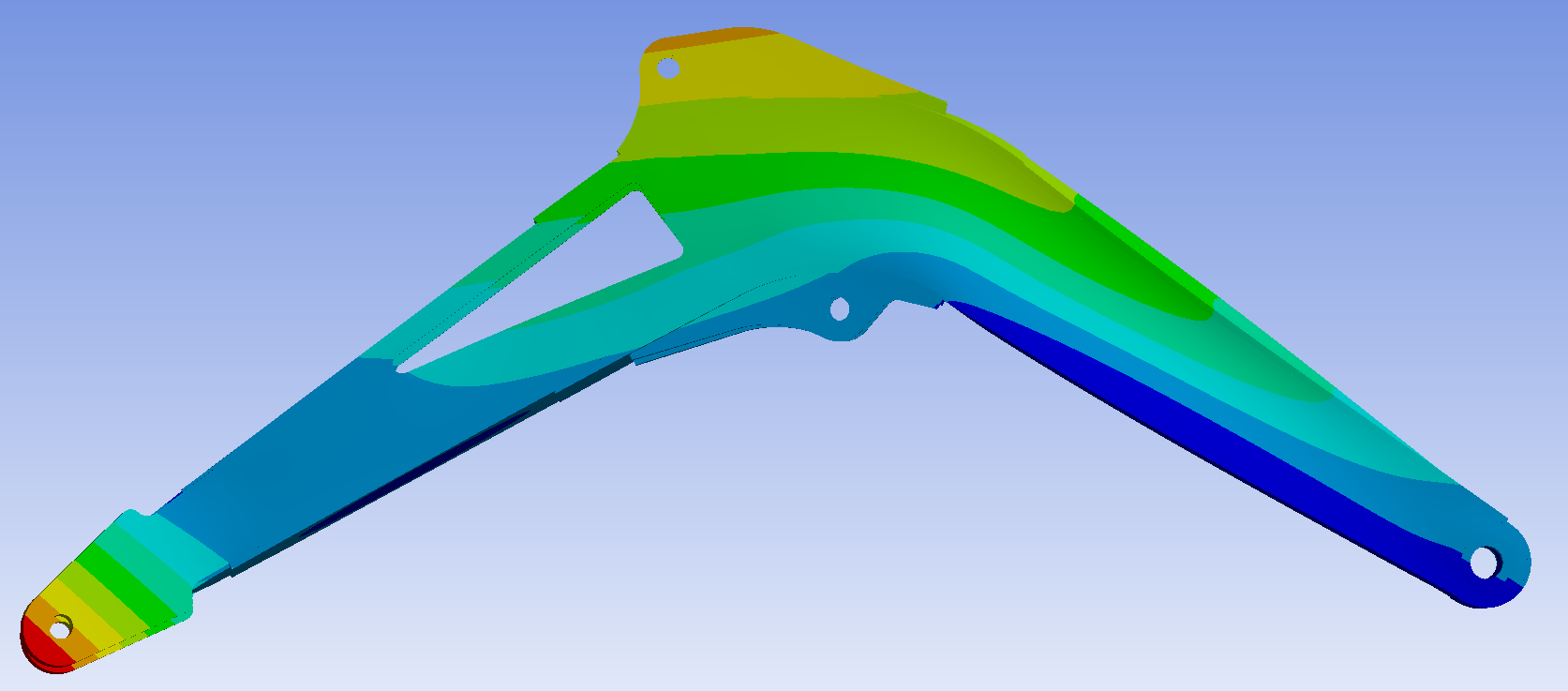
Figure 24: Fourth order vibration mode of the boom
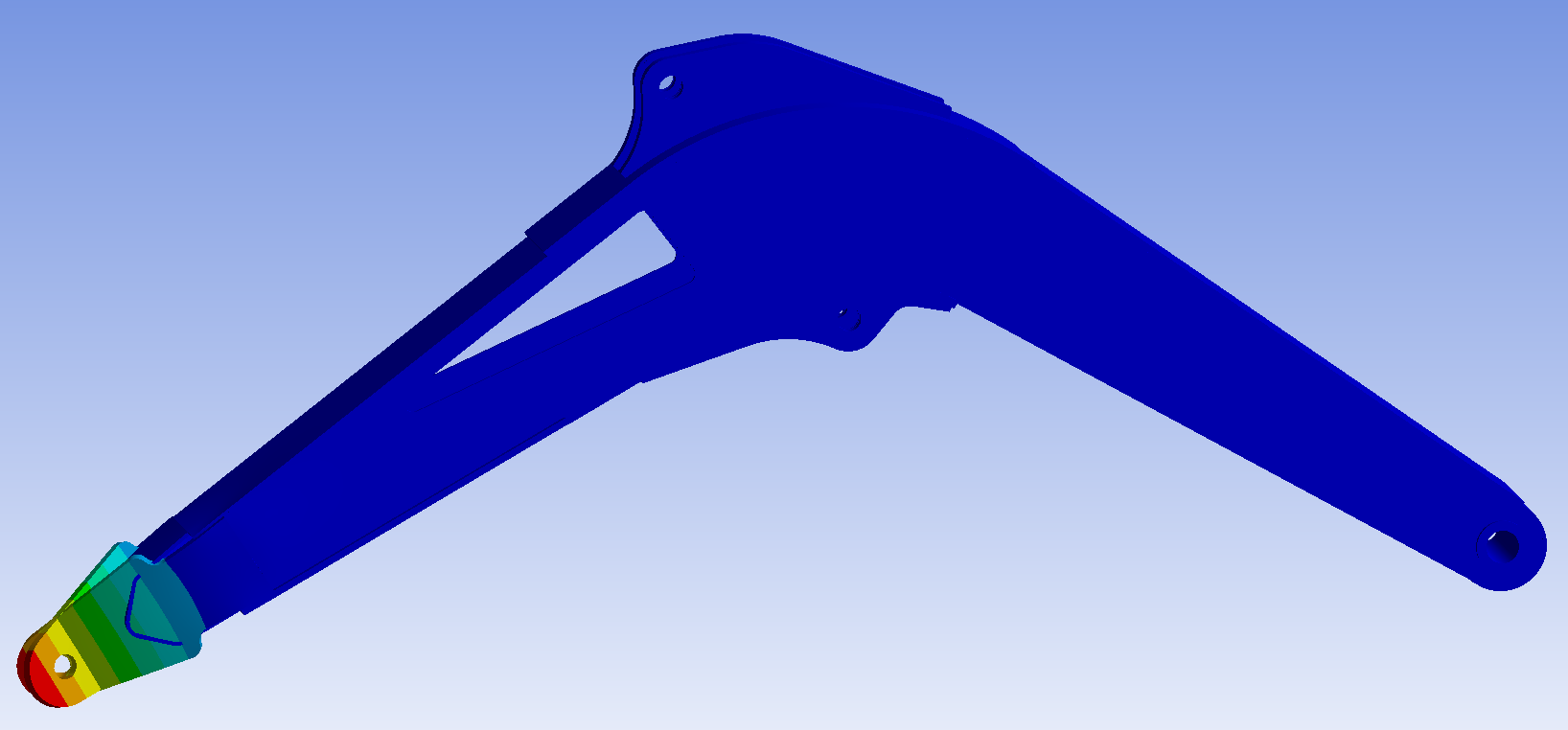
Figure 25: Fifth order vibration mode of the boom
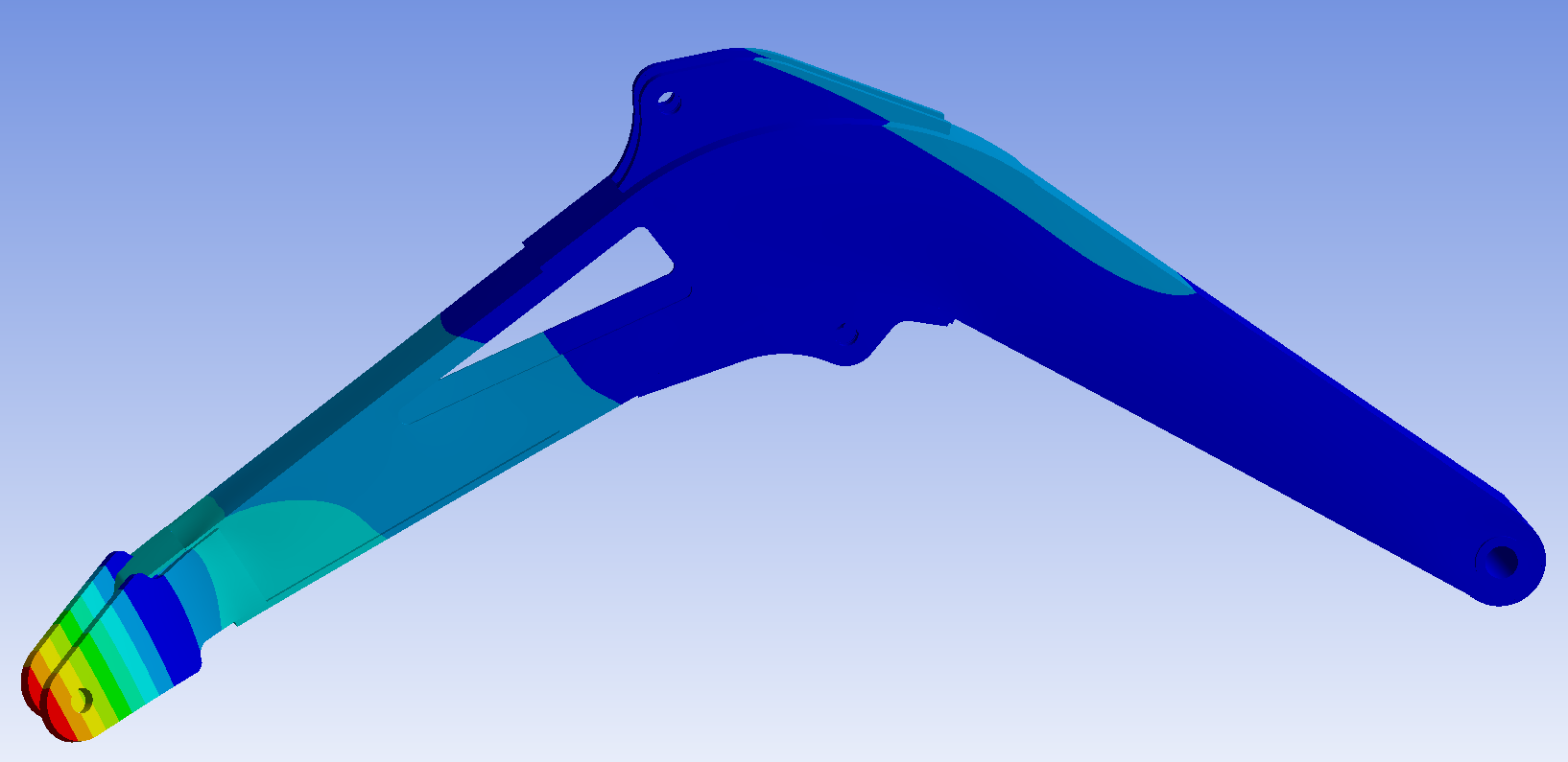
Figure 26: Sixth order vibration mode of the boom
After the boom is restrained, the first order vibration mode of the boom is the swing vibration at the hinge between the boom and the stick; The second order vibration mode is the left-right vibration of the first half of the boom; The third order vibration mode is the up and down vibration at the hinge between the boom and the stick and at the hinge between the boom and the fuselage; The fourth order vibration mode is the left-right opposite direction vibration of the articulated part between the boom and the stick and the upper ear plate of the boom; The fifth order vibration mode is the left-right opening and closing vibration at the articulation of the boom and the stick; The sixth order vibration mode is left-right vibration at the junction of the boom and the stick and at the middle of boom. The high-order vibration mode diagrams of the boom are relatively complex. In the actual production process, appropriate additional reinforcement can be made at these positions to increase its service life.
6. Conclusion
In this paper, the excavator boom is optimized based on Ansys and Design-Expert software. The optimization conclusions are as follows:
(1) Through the results of the finite element analysis, it can be seen that the maximum stress of the boom under the three working conditions is 197.56 MPa under the bucket excavation working condition, the maximum displacement is 5.9138 mm under the bucket excavation working condition, and the bucket excavation working condition is the dangerous working condition under the three typical working conditions.
(2) Through the variance analysis table, we can know that the mathematical model is significant, which shows that the mathematical model is correct, and through the mathematical regression equation, we can get the optimal solution combination of the corresponding boom parameters. The optimized boom mass is reduced by 19.31%.
(3) The performance of the optimized boom model is evaluated, and the strength and stiffness of the optimized model are proved to meet the safety requirements through finite element static analysis. The modal analysis provides reference suggestions for the subsequent design.
(4) This paper has guiding significance for the design and performance improvement of excavator boom in the future, and also provides ideas and methods for the optimization of similar mechanical structures.
Funding
The paper is funded by the Jiangsu Normal University Graduate Research Innovation Program (2024XKT0642).
Author contributions
Xing proposed the concept and approach of research and guided its progress. Sun conducted literature search, experimental design, data collection, data analysis, and drafting of manuscripts. Xing has conducted multiple reviews of the manuscript and proposed important revision suggestions, guiding Sun to revise and improve this manuscript. All authors have read and agreed to the content of the manuscript.
References
[1]. Chen, X., Liu, Q. and Zhang, M. (2024) Multi Objective Optimization Design and Verification of Boom of Medium Hydraulic Excavator. Construction Machinery and Equipmen, 55, 127-130.
[2]. Zhao, Z.Y., Zhu, Y. and Cheng, X.Q. et al. (2024) Topology Optimization Design and Simulation Analysis of The Secondary Arm of Three Arm Excavator Based on Inspire. Journal of Machine Design, 2023, 1-6.
[3]. Wang, Z.S., Wang, Z.D. and Zhang, S.H. (2022) Optimization Design of Boom Structure of Hydraulic Excavator. Chinese Journal of Construction Machinery, 20, 75-80.
[4]. Pang, C.L. and Wu, S.J. (2022) Strength Check and Lightweight Design of Excavator Boom Based on Finite Element Analysis. Equipment Manufacturing Technology, 2, 47-49.
[5]. Wang, F.F. and Yang, L.H. (2024) Optimization Design of Mechanical Structure of A Controllable Excavator. Construction Machinery Technology & Management, 37, 38-41.
[6]. Ning, X.B., Liu, Y.R. and Li, J. et al. (2017) New Structure of Large Hydraulic Excavator Stick Based on Topology Optimization Method. China Mechanical Engineering, 28, 1936-1942.
[7]. Li, J.J. and Sui, Z. (2019) Topology Optimization Design of Hydraulic Excavator Stick Structure. Group Technology & Production Modernization, 36, 10-14.
[8]. Huang, J.N., Wang, X. and Liu, S.L. (2019) Finite Element Analysis and Optimization Design of Hydraulic Excavator Boom. Tractor & Farm Transporter, 46, 29-32.
[9]. Jiang, L.G., Chu, J.R. and Liu, P.C. (2017) Research on Lightweight Design of Excavator Boom Structure. Agricultural Equipment & Vehicle Engineering, 55, 79-84.
[10]. Xiang, Q., Zhang, H. and Hu, X.L. (2015) Research on Lightweight Design Method of Hydraulic Excavator Boom Based on Ansys and Neural Network. Machine Tool & Hydraulics, 43, 136-140.
[11]. Bezkorovayny, P.G., Shestakov, V.S. and Nesterov, V.I. (2021) Optimization of Work Equipment Hydraulic Excavators. Mining Equipment and Electromechanics, 158, 3-8.
[12]. Qiang, S.Y., Long, X.H. and Hui, Z.S. et al. (2021) Knowledge-Based Structure Optimization Design for Boom of Excavator. Mathematical Problems in Engineering, 2021, 1-14.
[13]. Jalal, M., Irina, O. and Vitaly, G. et al. (2021) Optimization Design of The Stick of An Excavator Under Uncertain Loading (in the conditions of the Syrian Arab Republic). Matec Web of Conferences, 341, 1-9.
[14]. Suryo, H.S., Harto, H. and Yunianto, B. (2020) Optimization of Cat 374D L Arm Excavator Structure Topology Design Using Finite Element Methods. Rotasi, 22, 79-86.
Cite this article
Sun,B.;Xing,B. (2025). Research on Optimization Design of Excavator Boom Structure Based on Finite Element Analysis. Applied and Computational Engineering,153,26-42.
Data availability
The datasets used and/or analyzed during the current study will be available from the authors upon reasonable request.
Disclaimer/Publisher's Note
The statements, opinions and data contained in all publications are solely those of the individual author(s) and contributor(s) and not of EWA Publishing and/or the editor(s). EWA Publishing and/or the editor(s) disclaim responsibility for any injury to people or property resulting from any ideas, methods, instructions or products referred to in the content.
About volume
Volume title: Proceedings of the 3rd International Conference on Mechatronics and Smart Systems
© 2024 by the author(s). Licensee EWA Publishing, Oxford, UK. This article is an open access article distributed under the terms and
conditions of the Creative Commons Attribution (CC BY) license. Authors who
publish this series agree to the following terms:
1. Authors retain copyright and grant the series right of first publication with the work simultaneously licensed under a Creative Commons
Attribution License that allows others to share the work with an acknowledgment of the work's authorship and initial publication in this
series.
2. Authors are able to enter into separate, additional contractual arrangements for the non-exclusive distribution of the series's published
version of the work (e.g., post it to an institutional repository or publish it in a book), with an acknowledgment of its initial
publication in this series.
3. Authors are permitted and encouraged to post their work online (e.g., in institutional repositories or on their website) prior to and
during the submission process, as it can lead to productive exchanges, as well as earlier and greater citation of published work (See
Open access policy for details).
References
[1]. Chen, X., Liu, Q. and Zhang, M. (2024) Multi Objective Optimization Design and Verification of Boom of Medium Hydraulic Excavator. Construction Machinery and Equipmen, 55, 127-130.
[2]. Zhao, Z.Y., Zhu, Y. and Cheng, X.Q. et al. (2024) Topology Optimization Design and Simulation Analysis of The Secondary Arm of Three Arm Excavator Based on Inspire. Journal of Machine Design, 2023, 1-6.
[3]. Wang, Z.S., Wang, Z.D. and Zhang, S.H. (2022) Optimization Design of Boom Structure of Hydraulic Excavator. Chinese Journal of Construction Machinery, 20, 75-80.
[4]. Pang, C.L. and Wu, S.J. (2022) Strength Check and Lightweight Design of Excavator Boom Based on Finite Element Analysis. Equipment Manufacturing Technology, 2, 47-49.
[5]. Wang, F.F. and Yang, L.H. (2024) Optimization Design of Mechanical Structure of A Controllable Excavator. Construction Machinery Technology & Management, 37, 38-41.
[6]. Ning, X.B., Liu, Y.R. and Li, J. et al. (2017) New Structure of Large Hydraulic Excavator Stick Based on Topology Optimization Method. China Mechanical Engineering, 28, 1936-1942.
[7]. Li, J.J. and Sui, Z. (2019) Topology Optimization Design of Hydraulic Excavator Stick Structure. Group Technology & Production Modernization, 36, 10-14.
[8]. Huang, J.N., Wang, X. and Liu, S.L. (2019) Finite Element Analysis and Optimization Design of Hydraulic Excavator Boom. Tractor & Farm Transporter, 46, 29-32.
[9]. Jiang, L.G., Chu, J.R. and Liu, P.C. (2017) Research on Lightweight Design of Excavator Boom Structure. Agricultural Equipment & Vehicle Engineering, 55, 79-84.
[10]. Xiang, Q., Zhang, H. and Hu, X.L. (2015) Research on Lightweight Design Method of Hydraulic Excavator Boom Based on Ansys and Neural Network. Machine Tool & Hydraulics, 43, 136-140.
[11]. Bezkorovayny, P.G., Shestakov, V.S. and Nesterov, V.I. (2021) Optimization of Work Equipment Hydraulic Excavators. Mining Equipment and Electromechanics, 158, 3-8.
[12]. Qiang, S.Y., Long, X.H. and Hui, Z.S. et al. (2021) Knowledge-Based Structure Optimization Design for Boom of Excavator. Mathematical Problems in Engineering, 2021, 1-14.
[13]. Jalal, M., Irina, O. and Vitaly, G. et al. (2021) Optimization Design of The Stick of An Excavator Under Uncertain Loading (in the conditions of the Syrian Arab Republic). Matec Web of Conferences, 341, 1-9.
[14]. Suryo, H.S., Harto, H. and Yunianto, B. (2020) Optimization of Cat 374D L Arm Excavator Structure Topology Design Using Finite Element Methods. Rotasi, 22, 79-86.