


1. Introduction
Energy deficiency is a huge problem that many countries have struggled with. In the past few years, many thermal power plants have been closed because of high costs and pollution and replaced by renewable power plants. However, not until recently, especially in China, dramatic climate changes are frequently striking new records of the highest air temperature, which is a catastrophe for both hydraulic and wind power systems. There is a tremendous drop in water lines, and behaviors of airstreams have also been affected significantly. To cope with this unexpected energy crisis, many electricity rationing policies are proposed, and many thermal power plants are resumed.
The thermal power system is still the most reliable electric energy generation method that humans can currently get control of, and this reflects the importance of heat engine studies.
Nowadays, the majority of thermal power plants are in the form of gas turbines. Thus, countless types of research on this topic have long been carried out by predecessors in which most of them are pursuing the same goal, achieving high efficiency. The efficiency of a stationary gas turbine determines how much useful energy can be produced in a given amount of resources, and that is vital to any power plant economically and environmentally. In this report, the content and information this research discovered will be presented, revolving around power plant systems. Different design mechanisms and maintenance methods for improving thermal efficiency are explained.
2. Design Mechanism
In this section, various design concepts that engineers have developed to increase the thermal efficiency of a gas turbine system are explained. Design mechanisms can be divided into two major categories: Complex cycle and Combined cycle.
2.1. Simple to Complex
Normally, a gas turbine is modeled and analyzed by an air-standard Brayton cycle, in which the efficiency is given by: Work Output/Heat Input.
A simple Brayton cycle has a thermal efficiency of 20~35%, where the back work ratio (work demand from the compressor compared to the work output from the turbine) is around 60% which significantly limits the efficiency [1]. To improve based on that, a standard Brayton cycle can be made into a complex one with more networks and higher efficiency. Three methods are mentioned below.
2.1.1. Regeneration. Considering an opened loop gas turbine system, exhaust gases passing out from the turbine always have a higher temperature than the inlet gases and the ambient environment, which means that heat is always rejected from the system to the environment. The more significant the temperature difference, the less heat has been utilized in useful work, so the efficiency is kept low.
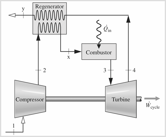
In this case, a regeneration system is usually added so that rejected heat can be recovered to some degree by heating up gases before the combustion stage. Since exhaust gas has a higher temperature than the inlet gas, when placed close enough in a regenerator, heat will spontaneously transfer to the latter. In turn, according to figure 1, Tx will be greater than T2, so less fuel is required during the combustion stage for the gas expansion. Consequently, less fuel demand stands for lower heat in, and thermal efficiency increases. Calculations have shown that the overall efficiency could increase by more than 10% [2].
2.1.2. Reheat
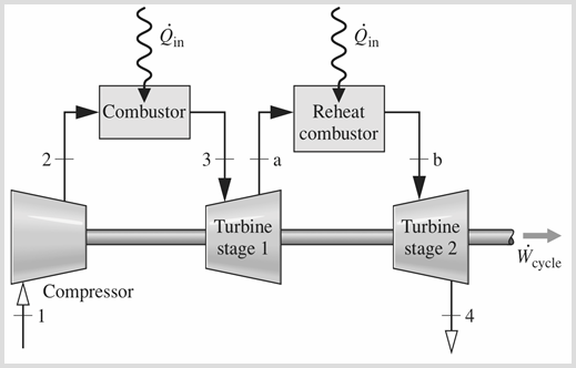
In another method, the reheat process, second or even more turbines are added to the system, and the exhaust gas from the first turbine will be reheated to power the second turbine, producing more work. In other words, the expansion stage has been divided into two or more.
|
Fig. 1. Regeneration schematic. |
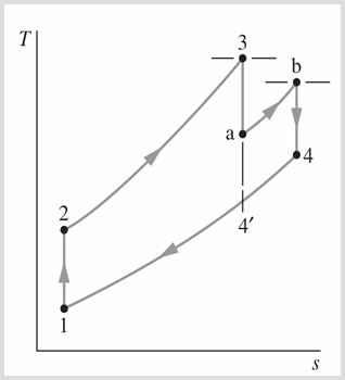
By looking at the T-S diagram from figure 3, noticing that instead of expanding from state 3 to 4´, it expands halfway to state a, then heats up again to state b, and lastly expands again to state 4.
The benefit of a reheat process is that it produces more work in a cycle. However, more work output does not necessarily mean that efficiency increases. In fact, the reheat process always decreases the efficiency, when it is used alone. That is because there is more heat input happening at the reheat combustor. It can be seen in figure 4, where T4 is higher than T4´, suggesting that ∆T between state 4 and state 1 is larger and that thermal efficiency decreases.
Even though a high exhaust temperature may not be ideal for thermal efficiency, it provides a great potential to add a regenerator, as the large temperature difference will offer a high rate of heat transfer from the exhaust gas to the inlet gas. This is also the reason why reheat is often combined with the regeneration process.
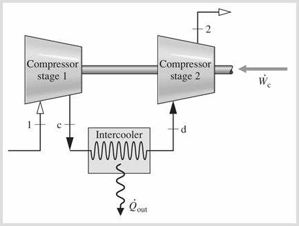
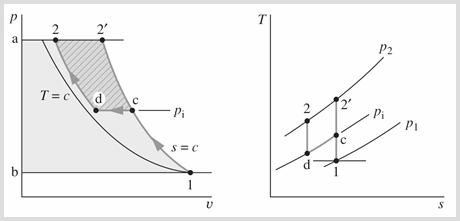
2.1.3. Inter-cooling. The inter-cooling process is similar to reheat; it is a multi-stage compression process in which a second compressor is introduced. During the process, the gas is cooled before entering the second compressor. Since cooling the gas makes it denser and easier to be compressed, it results in a decrement in compressor work demand. Then, as the back work ratio drops, the work output from the turbine increases.
From the P-V diagram in figure 5, comparing the normal compression process (1-c-2`) and the inter-cooling compression process (1-c-d-2), the area under the inter-cooling path from limits a and b is relatively smaller, which means that less work is required for inter-cooling compression.
|
|
Fig. 2. Reheat schematic. | Fig. 3. TS Diagram of reheat. |
Nevertheless, having the same issue with reheat, the inter-cooling process could decrease the efficiency due to the fact that extra heat is rejected to the environment at the intercooler. So, it is also often combined with a regenerator.
|
|
Fig. 4. Inter-cooling schematic. | Fig. 5. PV & TS diagram of inter-cooling. |
2.1.4. Complex Cycle. As the previous paragraphs explained, regeneration, reheat, and inter-cooling processes have great potential to work together. When they are combined, they alter a simple Brayton cycle into a more complex one and maximize the work output and efficiency [3].
2.2. Combined Cycle
Apart from concerning only one power cycle, more cycles can be implemented into the system to improve efficiency. The wasted heat rejected from the primary cycle can be reused to power a secondary or subsidiary power cycle. This type of system can utilize more heat to work, so-called combined cycles.
There are lots of different combinations of cycles, using energy from gas, steam, or biomass. Nowadays, the most common and efficient one is the combined steam and gas turbine power system.
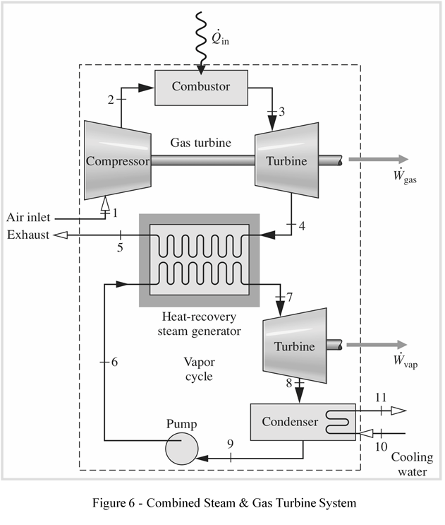
2.2.1. Combined Steam and Gas Turbine System. As the name suggests, this is a power system that operates under two cycles, steam, and gas. The gas turbine is the primary cycle where heat is put into the system through combustion, and the rejected heat from this cycle is recovered to power the secondary steam cycle which does not require any extra heat. Both cycles produce work from their rotating turbines and are connected to electric generators. Figure 6 shows a simplified plain view of this type of system.
When it comes to system analysis and calculations, it is relatively more complicated because there are two different cycles and dependent on each other. While the primary gas turbine is modeled by the Brayton cycle, the steam turbine is classified into the Rankine cycle.
Steam and gas combined power plants can also be designed into different configurations, where the most common ones are 1x1 and 2x1.
• 1x1 multi-axis — one gas turbine works with one steam turbine, connecting to two independent generators.
• 1x1 uniaxial — one gas turbine with one steam turbine but connect to one common generator.
• 2x1 — two independent gas turbines are operated with individual generators and heat recovery systems, powering one steam turbine.
Multi-axis configurations have an advantage over single axis in that the gas turbine can work individually under steam turbine failures. However, multi-axis configuration requires more investment and space in construction [4].
When uni-axial confronts the problem of steam turbine failures, a clutch is usually added. The clutch can disconnect the steam turbine from the generator. So when it fails, it will not affect the power generation of the gas turbine.
The advantage of a 2x1 is that two steam recovery systems are powering the steam turbine together so that no auxiliary boiler is needed for the process. Moreover, since generators all work individually, regular inspections and maintenance can be carried out easily. Nevertheless, due to the size and number of components of the system, the investment in the project is extremely high.
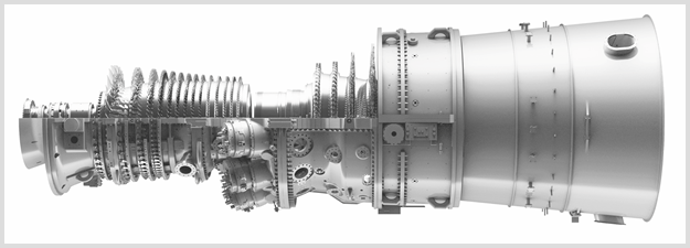
2.2.2. GE’s 7HA Gas Turbine Power Plant. In Nagoya, Japan, 2018, Chubu electric power station block No. 7-1 has set the new record of the greatest overall efficiency for the stationary gas turbine as high as 63.08% [5]. The system is a combined steam and gas with a configuration of 3x1, which means that three gas turbines with one steam turbine. The system uses the 7HA gas turbine provided by the general electric company (GE) in United State. This H-class turbine is powered by liquified natural gas and is capable of working under a condition of 1600˚C and a pressure ratio of 21:1. The power output is around 1,188,200 kW [6].
|
Fig. 6. Combined steam & gas turbine system. |
GE has been improving on the 7HA gas turbine from version 7HA.01 to 7HA.03 with a single cycle power increment from 290MW to 430MW. They also offer their 7HA turbine for different cycle configurations [6].
3. Maintenance
Previous sections are explaining how different design mechanisms can be used to achieve high efficiency in a power system. However, the maintenance of a gas turbine plays an equally important role in the system's efficiency. Remembering that many components of a gas turbine are like consumables, they become older and older. In a long term, they affect efficiency significantly and contribute to many types of performance deteriorations.
|
Fig. 7. GE’s 7HA gas turbine. |
3.1. The Source of Performance Deterioration
Thus, it is necessary to understand why machines get old and practical solutions to maintain their performance. Three main factors cause performance deterioration: fouling, erosion, and corrosion.
3.1.1. Fouling. Fouling happens when adhesive contaminants gradually build up in the system. This would alter the aero-geometry of airfoils [7], change the air inlet angle, increase the surface roughness of components, and raise the overall friction, contributing to the efficiency loss.
Fouling is an issue every gas turbine confronts, especially in the compressor where fouling takes place the most. According to research from Marco Zuniga [8], computational and experimental models have estimated that around 80% of compressor performance loss is due to fouling, resulting in a 5% drop in mass flow rate and 3.5% of overall efficiency decrement.
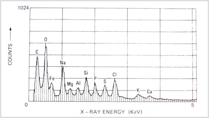
From the same research, an X-ray spectrum of different elements from the deposition on compressor blades is provided in figure 8. As the numbers suggest, carbon and oxygen take up the most counts, followed alone by other elements such as magnesium and aluminum. Moreover, the average size of contaminant particles is smaller than 2µm.
The source of contaminants is mainly dirt, dust, pollen, insects, oil vapor, and other industrial chemicals. Depending on the location, seawater salts could also be one for stations near coastlines.
On the other hand, fouling can be found in turbine blades as a result of contaminants produced by combustions. It is less significant compared to the compressor.
3.1.2. Erosion. Erosion is quite the opposite of fouling. Instead of building contaminants up in the system, it takes place when a relatively larger solid particle, around 20µm in diameter, enters the system, strikes hard on the original components in the flow path, and breaks materials off. The source of contaminants can be particles from ambient air, broken materials of the engine itself, or pieces of ice from cooling systems.
|
Fig. 8. X-Ray spectrum table. |
Similar to fouling, erosion causes undesirable shapes of airfoils and increases the roughness and friction of the system, leading to performance degradation. In addition, erosion is a non-reversible process, which makes it not easy to recover.
3.1.3. Corrosion. When the original components react chemically with contaminants, the system could suffer from corrosion. Corrosion in the compressor is referred to cold corrosion, while hot corrosion is in combustor and turbine sections.
Cold corrosion takes place when wet contaminants such as salts, mineral acids, reactive gases, chlorine, or sulfides react with the component. In hot corrosion, under an extremely high temperature and pressure environment, oxidation between metals and oxygen could be happening easily [9].
Again, erosion changes the component's shape and surface quality, causing efficiency to decrease. Same to erosion, it is a non-reversible deterioration.
3.2. Maintenance Solutions
Many maintenance methods have been developed to cope with performance deterioration problems mentioned above. The most effective and common ones are filtration, washing, and coating. They are explained below, revolving around the compressor and turbine.
3.2.1. Compressor Maintenance Considerations. One key factor that makes compressor performance degradation so severe is due to the inter-cooling system. In many power plants, inter-cooling is achieved by an inlet fogging system in which water droplets are sprayed into the compressing hot air to cool them down by evaporation. This was designed to evaporate all of the water before the air enters the compressor. Unfortunately, in practice, there is always some moisture getting into the compressor which increases the rate of fouling, erosion, and corrosion.
The maintenance of the compressor can be derived from two-point: preventing contaminants from entering the compressor and washing or recovering the compressor when deterioration already happened.
Compressor Filtration. A filter can be installed to avoid contaminants present in the system. It is relatively easier for stationary gas turbine systems to install filters than aviation turbines. The modern filtration process consists of multiple stages. In the case of compressor maintenance, it is referenced to inlet air filtration.
Inlet air filtration is responsible for the quality of the ambient air entering the system. Many parameters such as filter media, filter size, filter density, and electrostatic charges will affect the way a filter removes contaminants [9].
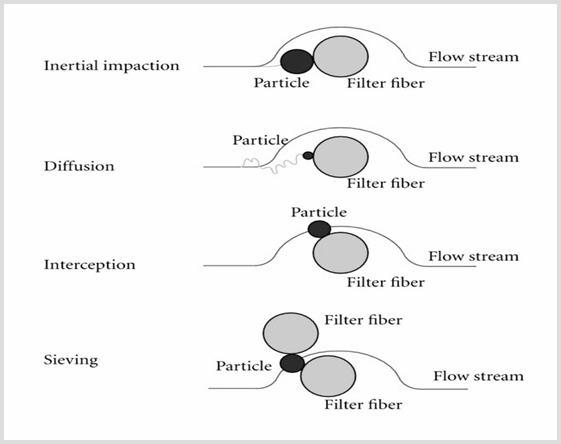
Figure 9 shows some mechanisms that how contaminant particles of various sizes can be trapped in a filter. The sieving is the most common one where the particle is not small enough to pass through the filter gap. Inertial Impaction works when the contaminant particle is larger than 1µm. The particle will have relatively larger inertia when moving at a high velocity so that it will attach to the filtration media as they collide. Nevertheless, smaller particles, around 0.01µm to 1µm, can be attracted to the filter even by electrostatic charges. This method is very effective, but over time, filter gradually loses their charges and become neutral [9].
A downside of filtration is that it reduces the pressure ratio and the engine performance due to airflow restrictions. Consequently, more fuel is needed or power output has to be taken down.
Compressor Washing. As mentioned above, filters can reduce the number of contaminants entering the system, but fouling will eventually happen, so washing is important. There are two major types of washing: off-line washing and on-line washing.
Off-line washing can be carried out only when the power system is turned off, and components are dissembled for washing. Components are cleaned manually with brushes or by ingesting synthetic particles to hit off depositions on blades. Off-line washing is very effective for fouling and is a suitable solution for severe fouling. In fact, washing off-line could also be erosive to the components, causing some material to lose.
|
Fig. 9. Common filtration mechanism. |
On-line washing was developed later for less severe fouling and can be done while the system is still operating. In the process, demineralized water, detergent, or specific solvent are chosen to be injected into the system. As the system runs through a cycle, washing liquid will clean the system [8].
Protective Coating. The Coating is very effective for preventing corrosion as it provides a protective layer between the original components and reactive chemicals.
|
Fig. 10. Material corrosion resistance comparison. |
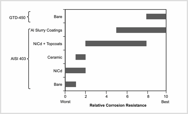
Whether a coating is needed or not depends on the material used in the component. Older types of compressor or turbine blades are usually made in stainless steel which is very reactive to chemicals. So, the coating is pretty essential. However, lots of new materials of alloys are invented that naturally have good resistance to chemical contaminants. The table in figure 10 below, provided by Robert Hoeft [10], shows a comparison between two types of blade materials, 403SS and GTD-450.
403SS is made of stainless steel. As the table indicates, when it is used uncoated, it provides little corrosion resistance. When it is coated with ceramics or aluminum, the resistance increases. On the contrary, looking at GTD-450 which is a metal alloy having its debut in MS7001F turbine, even when it is used barely, it has excellent corrosion resistance. However, the disadvantage of GTD-450 is that this material is extremely expensive, and requires more time for cooling processes.
Ceramic coating is frequently used to resist corrosion, but ceramic itself is a brittle material that is fragile to erosions, and it needs professional installations and very high costs.
3.2.2. Turbine Maintenance Considerations. The performance degradation of the turbine is not that significant compared with the compressor, but it is still necessary. For the maintenance of the turbine, filtration, washing, and coating are still used even though the cause of the problem is different.
The biggest difference in turbine performance degradation is the fuel choice. The hot sections of a gas turbine include the combustor and the turbine which undergo the combustion stages and emission gases. Different choices of fuel results in different composition and types of emission gases, causing corrosion at various levels.
Controlling the combustion in the system is key for the life span of hot section components. Overheating and over-fueling can cause serious damage to the system and even causes safety issues. Damages include fuel control stability problems and internal injector blockage over time. As a consequence, they could lead to severe explosions [10].
4. Conclusion
In conclusion, there are many factors affecting the thermal efficiency of a stationary gas turbine. Every gas turbine station varies due to its specific applications, locations, the material available, and project budget.
On the side of the system design mechanism, complex cycles and combined cycles can be implemented to increase the overall power and efficiency. While regeneration, reheat, or inter-cooling processes can maximize the efficiency of one power cycle, secondary cycles such as steam turbines can also be very effective on heat recoveries. On the side of system performance maintenance, filtration, washing, and protective coating are often used to slow down the process of fouling, erosion, and corrosion, thus reducing the rate of performance degradation.
As the report explained, there are countless combinations and ways that a gas turbine power station can be designed or maintained, and yet there are still tons of topics waiting to be discovered and studied.
References
[1]. [2022, "Thermal efficiency - Wikipedia", En.wikipedia.org [Online]. Available: https://en.wikipedia.org/wiki/Thermal_efficiency. [Accessed: 04- Aug- 2022]
[2]. Goktun, S., and Yavuz, H., 1999, "Thermal efficiency of a regenerative Brayton cycle with isothermal heat addition", Maritime Faculty, Tuzla, Istanbul, Turkey.
[3]. Ibrahim, T., Mohammed, M., Al Door, W., Al-Sammarraie, A., and Basrawi, F., 2020, "Study of The Performance of The Gas Turbine Power Plants From The Simple To Complex Cycle: A Technical Review", Department of Mechanical Engineering, Tikrit University, Tikrit, Iraq.
[4]. Larson, A., 2018, "Benefits of Single-Shaft Combined Cycle Power Plants", POWER Magazine.
[5]. 2018, "GE's HA Gas Turbine Delivers Second World Record for Efficiency | GE News", Ge.com [Online]. Available: https://www.ge.com/news/press-releases/ges-ha-gas-turbine-delivers-second-world-record-efficiency. [Accessed: 22- Aug- 2022].
[6]. "7HA Gas Turbine | GE Gas Power", gepower-v2 [Online]. Available: https://www.ge.com/gas-power/products/gas-turbines/7ha. [Accessed: 24- Aug- 2022].
[7]. 2020, "What Causes Performance Degradation in a Gas Turbine Engine", Sensatek, 850.321.5993.
[8]. VIGUERAS ZUÑIGA, M., 2007, "ANALYSIS OF GAS TURBINE COMPRESSOR FOULING AND WASHING ON LINE", PhD, Cranfield University.
[9]. Kurz, R., and Brun, K., 2012, "Technology Review of Modern Gas Turbine Inlet Filtration Systems", Hindawi, 2012(128134).
[10]. Hoeft, R., Janawitz, J., and Keck, R., Heavy-Duty Gas Turbine Operating and Maintenance Considerations, General Electric (GE), Atlanta.
Cite this article
Wu,Y. (2023). Achieving a high efficiency on stationary gas turbine. Applied and Computational Engineering,5,263-272.
Data availability
The datasets used and/or analyzed during the current study will be available from the authors upon reasonable request.
Disclaimer/Publisher's Note
The statements, opinions and data contained in all publications are solely those of the individual author(s) and contributor(s) and not of EWA Publishing and/or the editor(s). EWA Publishing and/or the editor(s) disclaim responsibility for any injury to people or property resulting from any ideas, methods, instructions or products referred to in the content.
About volume
Volume title: Proceedings of the 3rd International Conference on Signal Processing and Machine Learning
© 2024 by the author(s). Licensee EWA Publishing, Oxford, UK. This article is an open access article distributed under the terms and
conditions of the Creative Commons Attribution (CC BY) license. Authors who
publish this series agree to the following terms:
1. Authors retain copyright and grant the series right of first publication with the work simultaneously licensed under a Creative Commons
Attribution License that allows others to share the work with an acknowledgment of the work's authorship and initial publication in this
series.
2. Authors are able to enter into separate, additional contractual arrangements for the non-exclusive distribution of the series's published
version of the work (e.g., post it to an institutional repository or publish it in a book), with an acknowledgment of its initial
publication in this series.
3. Authors are permitted and encouraged to post their work online (e.g., in institutional repositories or on their website) prior to and
during the submission process, as it can lead to productive exchanges, as well as earlier and greater citation of published work (See
Open access policy for details).
References
[1]. [2022, "Thermal efficiency - Wikipedia", En.wikipedia.org [Online]. Available: https://en.wikipedia.org/wiki/Thermal_efficiency. [Accessed: 04- Aug- 2022]
[2]. Goktun, S., and Yavuz, H., 1999, "Thermal efficiency of a regenerative Brayton cycle with isothermal heat addition", Maritime Faculty, Tuzla, Istanbul, Turkey.
[3]. Ibrahim, T., Mohammed, M., Al Door, W., Al-Sammarraie, A., and Basrawi, F., 2020, "Study of The Performance of The Gas Turbine Power Plants From The Simple To Complex Cycle: A Technical Review", Department of Mechanical Engineering, Tikrit University, Tikrit, Iraq.
[4]. Larson, A., 2018, "Benefits of Single-Shaft Combined Cycle Power Plants", POWER Magazine.
[5]. 2018, "GE's HA Gas Turbine Delivers Second World Record for Efficiency | GE News", Ge.com [Online]. Available: https://www.ge.com/news/press-releases/ges-ha-gas-turbine-delivers-second-world-record-efficiency. [Accessed: 22- Aug- 2022].
[6]. "7HA Gas Turbine | GE Gas Power", gepower-v2 [Online]. Available: https://www.ge.com/gas-power/products/gas-turbines/7ha. [Accessed: 24- Aug- 2022].
[7]. 2020, "What Causes Performance Degradation in a Gas Turbine Engine", Sensatek, 850.321.5993.
[8]. VIGUERAS ZUÑIGA, M., 2007, "ANALYSIS OF GAS TURBINE COMPRESSOR FOULING AND WASHING ON LINE", PhD, Cranfield University.
[9]. Kurz, R., and Brun, K., 2012, "Technology Review of Modern Gas Turbine Inlet Filtration Systems", Hindawi, 2012(128134).
[10]. Hoeft, R., Janawitz, J., and Keck, R., Heavy-Duty Gas Turbine Operating and Maintenance Considerations, General Electric (GE), Atlanta.