


1. Introduction
With the rapid advancement of the global economy and technological innovation, the automotive industry has witnessed remarkable growth [1-2]. In 2023, global vehicle sales reached approximately 86 million units, underscoring the sector's substantial scale and societal integration [3]. While automobiles have significantly enhanced daily mobility, traditional internal combustion engine (ICE) vehicles [4-5] face increasingly evident limitations, particularly in energy scarcity and environmental pollution. As a result, the development of zero-emission electric vehicles (EVs) [6] driven by renewable energy has become a dominant trend in the automotive industry, reflecting a critical shift toward sustainability and technological innovation.
Recent advancements in battery and motor technologies have significantly enhanced the performance of EVs. However, the rising popularity of high-power EVs has also led to a surge in traffic accidents caused by improper driver operation or deficiencies in vehicle control systems. Effectively managing these "beasts" has thus become a critical concern. Four-wheel-independently driven distributed drive systems can dynamically and optimally distribute the total demanded torque to each actuator, improving vehicle yaw and sideslip control, thereby enhancing handling stability and safety [7].
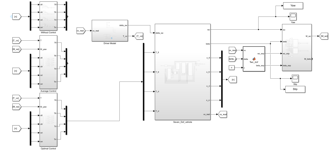
In this study, a MATLAB simulation model was developed based on research into four-motor distributed drive systems. The control performance of three strategies—no control, average torque distribution, and optimal torque distribution—was compared. The results demonstrate that optimal torque distribution significantly enhances vehicle stability under most operating conditions [8].
2. Dynamic simulation
2.1. Vehicle motion equation
2.1.1. Optimal control allocation
Objective: Distribute the four-wheel torques
Optimization Objective Function: Minimize the sum of squared tire load ratios, i.e., minimize energy loss:
Constraints:
1. Total driving force equilibrium: The sum of the torques from all four wheels equals the total driving force:
2. Yaw moment equilibrium: The torque difference between the left and right wheels balances the desired yaw moment:
The Lagrangian function is constructed using Lagrange multipliers:
Taking partial derivatives with respect to each torque and setting them to zero yields:
The equations reveal symmetry between
Substituting these into the constraints:
Total driving force constraint:
Yaw moment constraint:
Solving these equations gives:
Rear wheel torques are then:
Coefficient Simplification:
Similarly, we obtain:
Then:
2.1.2. Average control allocation
Objective: Distribute the total driving force equally among four wheels, while adjusting the left-right torque difference via
The torque difference
The aforementioned equally distributed torque allocation scenario is more suitable for simple, low-dynamic conditions. In this method, an increase in torque demand on one side results in a corresponding decrease on the opposite side. However, this approach has inherent limitations, as it neglects vertical load variations, potentially leading to wheel slippage or inefficient torque distribution. In contrast, the optimal allocation strategy accounts for vertical loads, enabling enhanced dynamic performance and energy efficiency.
2.1.3. Linear two-degree-of-freedom vehicle model
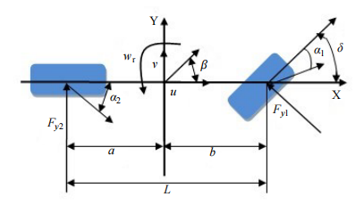
Differential Equations:
Vertical Loads:
The wheelbase
2.2. Select electric vehicle parameters
The vehicle model and selected vehicle parameters are shown in Figure 2 and Table 1
|
Vehicle Parameters |
|
|
Projects |
Values |
|
Vehicle mass |
1765kg |
|
Front axle track |
1.6m |
|
Rear axle track |
1.6m |
|
CG to front axle distance |
1.2m |
|
CG to rear axle distance |
1.4m |
|
Wheelbase |
2.6m |
|
CG height |
0.5m |
|
Yaw moment of inertia |
2700kg*m^2 |
|
Wheel moment of inertia |
2.5 kg*m^2 |
|
Cornering stiffness of the front axle |
-200e3N/rad |
|
Cornering stiffness of the rear axle |
-200e3N/rad |
2.3. Analysis of simulation results
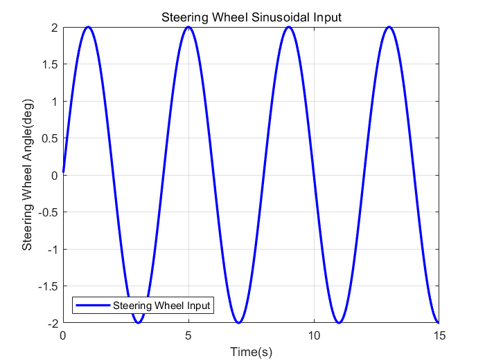
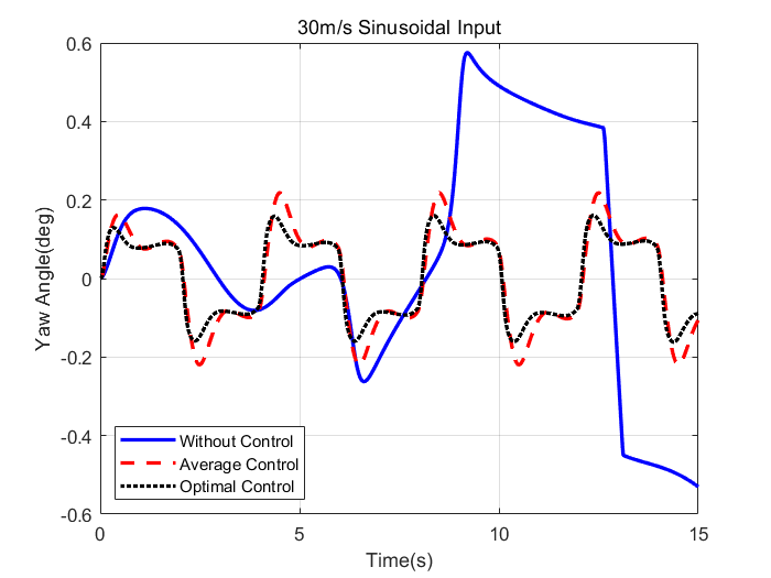
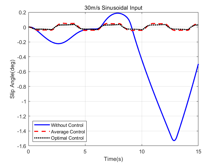
The simulation results of the vehicle at 30 m/s with sinusoidal steering wheel angle input (Figure 3) are shown in figure 4 and 5.
The experimental results under more working conditions are shown in Table 2 and Table 3.
|
Path |
Metric |
Sinusoidal Input |
||||
|
Without Control |
Average Control |
Improved |
Optimal Control |
Improved |
||
|
10m/s |
RMS Yaw Angle(deg) |
0.1984 |
0.2316 |
-16.75% |
0.2288 |
-15.31% |
|
Max Yaw Angle(deg) |
0.4947 |
0.3254 |
34.22% |
0.3257 |
34.15% |
|
|
RMS Slip Angle(deg) |
0.4616 |
0.0084 |
98.18% |
0.0065 |
98.59% |
|
|
Max Slip Angle(deg) |
1.4660 |
0.0208 |
98.58% |
0.0137 |
99.06% |
|
|
20m/s |
RMS Yaw Angle(deg) |
0.2087 |
0.1589 |
23.87% |
0.1415 |
32.19% |
|
Max Yaw Angle(deg) |
0.5744 |
0.2301 |
59.94% |
0.1929 |
66.41% |
|
|
RMS Slip Angle(deg) |
0.2322 |
0.0338 |
84.44% |
0.0250 |
89.26% |
|
|
Max Slip Angle(deg) |
0.8025 |
0.0455 |
94.33% |
0.0327 |
95.93% |
|
|
30m/s |
RMS Yaw Angle(deg) |
0.3023 |
0.1268 |
58.05% |
0.1036 |
65.72% |
|
Max Yaw Angle(deg) |
0.5751 |
0.2195 |
61.83% |
0.1619 |
71.86% |
|
|
RMS Slip Angle(deg) |
0.6379 |
0.0391 |
93.88% |
0.0264 |
95.87% |
|
|
Max Slip Angle(deg) |
1.5284 |
0.0512 |
96.65% |
0.0345 |
97.75% |
|
|
Path |
Metric |
Delayed Sinusoidal Input |
||||
|
Without Control |
Average Control |
Improved |
Optimal Control |
Improved |
||
|
10m/s |
RMS Yaw Angle(deg) |
0.1761 |
0.2098 |
-19.12% |
0.2067 |
-17.39% |
|
Max Yaw Angle(deg) |
0.4537 |
0.3260 |
28.15% |
0.3242 |
28.56% |
|
|
RMS Slip Angle(deg) |
0.2219 |
0.0072 |
96.77% |
0.0055 |
97.53% |
|
|
Max Slip Angle(deg) |
0.7501 |
0.0177 |
97.64% |
0.0116 |
98.45% |
|
|
20m/s |
RMS Yaw Angle(deg) |
0.1880 |
0.1411 |
24.92% |
0.1265 |
32.74% |
|
Max Yaw Angle(deg) |
0.4765 |
0.2294 |
51.86% |
0.1916 |
59.79% |
|
|
RMS Slip Angle(deg) |
0.3073 |
0.0304 |
90.1% |
0.0224 |
92.7% |
|
|
Max Slip Angle(deg) |
0.9797 |
0.0452 |
95.39% |
0.0326 |
96.67% |
|
|
30m/s |
RMS Yaw Angle(deg) |
0.2910 |
0.1177 |
59.54% |
0.0966 |
66.8% |
|
Max Yaw Angle(deg) |
0.5989 |
0.2195 |
63.36% |
0.1620 |
72.95% |
|
|
RMS Slip Angle(deg) |
0.5477 |
0.0359 |
93.44% |
0.0243 |
95.56% |
|
|
Max Slip Angle(deg) |
1.5494 |
0.0508 |
96.72% |
0.0345 |
97.77% |
|
Based on the data presented in Figures 4, 5 and Tables 2, 3, Under the optimal control, the maximum and RMS values of the vehicle's yaw angle and slip angle are significantly improved compared to those under average control and no control. This demonstrates that the optimal control effectively enhances vehicle stability and handling performance at speeds of 20 m/s and 30 m/s under both sinusoidal and delayed sinusoidal steering inputs.
However, the results indicate that the proposed algorithm does not achieve optimal control over the yaw angle RMS value in certain scenarios, such as at a speed of 10 m/s with sinusoidal or delayed sinusoidal steering inputs. Nevertheless, its impact on the yaw angle remains marginal, while the maximum value is substantially optimized. Therefore, it can still be concluded that vehicle stability is improved to some extent even under these conditions.
3. Conclusion
This study conducts a systematic analysis of torque distribution strategies for four-motor distributed drive vehicles, revealing the influence mechanisms of different control strategies on vehicle stability through theoretical modeling and simulation verification. The research establishes an optimal torque distribution model aiming to minimize the sum of squared tire load ratios. By incorporating constraints of total driving force and yaw moment, analytical expressions for four-wheel torques are derived using the Lagrangian multiplier method, and compared with the average distribution strategy and uncontrolled state. Simulation results show that under sinusoidal and delayed sinusoidal steering inputs, the optimal control strategy significantly enhances vehicle dynamic stability:
High-speed conditions (20–30 m/s): The maximum yaw angle is reduced by 58%–72%, and the root mean square (RMS) value is reduced by 58%–66%; the maximum sideslip angle is optimized by 93%–98%, and the RMS value is optimized by 89%–96%, effectively suppressing the risk of excessive yaw and sideslip during vehicle steering. Low-speed conditions (10 m/s): Although the optimization effect on the yaw angle RMS is limited (slightly increased in some scenarios), the sideslip angle is still optimized by 96%–99%, indicating the universal applicability of the optimal strategy for dynamic management of tire grip.
The study further finds that the average distribution strategy tends to cause uneven torque distribution under high-dynamic conditions due to neglecting differences in tire vertical loads. In contrast, the optimal strategy achieves collaborative optimization of driving force and yaw moment by introducing load weight coefficients, significantly improving tire friction utilization and energy efficiency.
In summary, the optimal torque distribution strategy effectively enhances vehicle handling stability and safety under most working conditions by dynamically adjusting four-wheel torques, providing a theoretical basis for the design of control algorithms for distributed drive vehicles. Future research can further integrate real-time road parameter sensing to optimize the robustness of the torque distribution model and adapt to complex driving environments.
References
[1]. A fast and parametric torque distribution strategy for four-wheel-drive energy-efficient electric vehiclesDizqah, A.M.; Lenzo, B.; Sorniotti, A.IEEE Trans Ind Electron, v 63, n 7, p 4367-4376, 2016
[2]. Torque optimization control for electric vehicles with four in-wheel motors equipped with regenerative braking systemXu, W.; Chen, H.; Zhao, H.Mechatronics, v 57, p 95-108, 2019
[3]. Road surface recognition based slip rate and stability control of distributed drive electric vehicles under different conditionsHongbo, W.; Boyang, Z.; Jinfang, H.Proc IMechE, Part D: J Automob Eng, v 237, n 10-11, p 2511-2526, 2023
[4]. All-wheel-drive torque distribution strategy for electric vehicle optimal efficiency considering tire slipCao, K.; Hu, M.; Wang, D.IEEE Access, v 9, p 25245-25257, 2021
[5]. Cooperative control of trajectory tracking and lateral stability of distributed driven electric vehicleZhang, Z.; Jin, B.J Chang Univ Sci Technol Nat Sci, v 20, n 6, p 159-169, 2023
[6]. An integrated control strategy of path following and lateral motion stabilization for autonomous distributed drive electric vehiclesZou, Y.; Guo, N.; Zhang, X.Proc IMechE, Part D: J Automob Eng, v 235, n 4, p 1164-1179, 2021
[7]. A supervisory control strategy of distributed drive electric vehicles for coordinating handling, lateral stability, and energy efficiencyGuo, N.; Zhang, X.; Zou, Y.rans Transp Electrification, v 7, n 4, p 2488-2504, 2021
[8]. MPC-based integrated control of trajectory tracking and handling stability for intelligent driving vehicle driven by four hub motorZhai, L.; Wang, C.; Hou, Y.IEEE Trans Vehicular Technol, v 71, n 3, p 2668-2680, 2022
Cite this article
Zhao,J. (2025). Research on Torque Distribution Strategy for Four-Motor Distributed Drive Vehicles. Applied and Computational Engineering,169,77-85.
Data availability
The datasets used and/or analyzed during the current study will be available from the authors upon reasonable request.
Disclaimer/Publisher's Note
The statements, opinions and data contained in all publications are solely those of the individual author(s) and contributor(s) and not of EWA Publishing and/or the editor(s). EWA Publishing and/or the editor(s) disclaim responsibility for any injury to people or property resulting from any ideas, methods, instructions or products referred to in the content.
About volume
Volume title: Proceedings of CONF-MSS 2025 Symposium: Machine Vision System
© 2024 by the author(s). Licensee EWA Publishing, Oxford, UK. This article is an open access article distributed under the terms and
conditions of the Creative Commons Attribution (CC BY) license. Authors who
publish this series agree to the following terms:
1. Authors retain copyright and grant the series right of first publication with the work simultaneously licensed under a Creative Commons
Attribution License that allows others to share the work with an acknowledgment of the work's authorship and initial publication in this
series.
2. Authors are able to enter into separate, additional contractual arrangements for the non-exclusive distribution of the series's published
version of the work (e.g., post it to an institutional repository or publish it in a book), with an acknowledgment of its initial
publication in this series.
3. Authors are permitted and encouraged to post their work online (e.g., in institutional repositories or on their website) prior to and
during the submission process, as it can lead to productive exchanges, as well as earlier and greater citation of published work (See
Open access policy for details).
References
[1]. A fast and parametric torque distribution strategy for four-wheel-drive energy-efficient electric vehiclesDizqah, A.M.; Lenzo, B.; Sorniotti, A.IEEE Trans Ind Electron, v 63, n 7, p 4367-4376, 2016
[2]. Torque optimization control for electric vehicles with four in-wheel motors equipped with regenerative braking systemXu, W.; Chen, H.; Zhao, H.Mechatronics, v 57, p 95-108, 2019
[3]. Road surface recognition based slip rate and stability control of distributed drive electric vehicles under different conditionsHongbo, W.; Boyang, Z.; Jinfang, H.Proc IMechE, Part D: J Automob Eng, v 237, n 10-11, p 2511-2526, 2023
[4]. All-wheel-drive torque distribution strategy for electric vehicle optimal efficiency considering tire slipCao, K.; Hu, M.; Wang, D.IEEE Access, v 9, p 25245-25257, 2021
[5]. Cooperative control of trajectory tracking and lateral stability of distributed driven electric vehicleZhang, Z.; Jin, B.J Chang Univ Sci Technol Nat Sci, v 20, n 6, p 159-169, 2023
[6]. An integrated control strategy of path following and lateral motion stabilization for autonomous distributed drive electric vehiclesZou, Y.; Guo, N.; Zhang, X.Proc IMechE, Part D: J Automob Eng, v 235, n 4, p 1164-1179, 2021
[7]. A supervisory control strategy of distributed drive electric vehicles for coordinating handling, lateral stability, and energy efficiencyGuo, N.; Zhang, X.; Zou, Y.rans Transp Electrification, v 7, n 4, p 2488-2504, 2021
[8]. MPC-based integrated control of trajectory tracking and handling stability for intelligent driving vehicle driven by four hub motorZhai, L.; Wang, C.; Hou, Y.IEEE Trans Vehicular Technol, v 71, n 3, p 2668-2680, 2022