


1. Introduction
The global trend towards replacing conventional fossil fuels with environmentally-friendly energy resources in the field of the automatic transmission has led to the increasing demand for automotive vehicles like hybrid electric vehicles (HEV) in the car industry [1]. According to Japanese-based research statistics, new HEV sales worldwide in 2021 rose 33% to around 3.1 million compared with the sales in 2020[2]. However, it seems that current automotive vehicles still suffer from problems like poor energy efficiency, low driving range caused by overweight batteries, and technical failures encountered in other electrical components. As a result, research efforts have been made on Energy Recovery Systems (ERS), which utilize exhaust gas as a source of energy to improve energy efficiency further and meet the increasing demand for advanced vehicle performance.
The types of ERS can be categorized as thermoelectric, Rankine cycle, and electric turbo compound (integrated, serial, parallel). Firstly, a thermoelectric energy recovery system is mainly composed of an Auxiliary Power Unit (APU), which consists of an internal combustion engine and a generator [3]. APU is connected in series with an electric motor and a final drive via an electrical line. The final drive is linked to the rear wheels and transmits power when necessary. The summarized working principle of the whole system is based on the thermoelectric effect (Seebeck Effect [4]). There is a temperature difference between the exhaust gas emitted and those which pass through the coolant [3]. Therefore, an electric voltage is generated as a consequence. It is then supplied to the battery and passed down to the electric motor linked to the final drive. Finally, the final drive drives the rear wheels with excess power, and the overall recovery procedure is accomplished. Numerous works have been carried out to implement thermoelectric technologies in conventional fuel vehicles. In 1988, the idea of inserting a thermoelectric generator into cars was first pointed out in Germany [1]. Later on in 1990s; the technology was tested in truck diesel engines by Hi-Z Technology Incorporation in the United States [1]. BMW has played a vital role in the development of thermoelectric technology; it has tested many prototypes, and the performances of different configurations are compared. In 2003, an experimental prototype produced 80W, and the first vehicle prototype was in 2009, producing around 200W [1]. A further investigation into the interactions between the technology and the powertrain and a prototype that only works at necessary conditions like changing directions was also proposed by the BMW Group in 2009.
The results indicated the necessity of developing economic materials suitable for working at low temperatures with productive efficiency [5]. From the text above, considerable investigations have been made on the technology in traditional fuel vehicles. However, research efforts on the technology in HEV, and EV are sadly rare. Deng et al. investigated the possibility of applying TEG in a hybrid vehicle equipped with a 42 V power net system [6]. Wang et al. studied an ambitious strategy to reach optimum energy saving when switching between different operation modes in the case of thermoelectric generators in HEV. Some advantages and drawbacks are also discussed in this paper: the good thing is that this type of technology is widely used in industrial applications like aerospace, cooling systems, and mobile phone charging. This means that researchers can investigate the efforts being made in other fields [5].
Moreover, the thermoelectric generator has solid-state constructions, ensuring durability during the active phase [7]. It is also favored due to its relative simplicity compared to systems like Rankine cycles. However, figures indicate a 33% higher fuel consumption with thermoelectric generators than conventional internal combustion engines [1]. This is because the whole system occupies a considerable weight and degrades fuel efficiency. Furthermore, strict temperature conditions are required for the system to reach its optimum working status. In other words, the system will perform horribly at temperatures other than the ideal range [3].
Another method to recover the thermal energy lost in the exhaust system is the Rankine cycle, a heat cycle commonly applied in steam power plants. Like the Rankine cycle in power plants, the ranking cycle in the combustion engine's exhaust system uses heat wasted in the exhaust gas to evaporate a coolant fluid and use the fluid's steam to generate electricity through an expander, as shown in Figure 1.
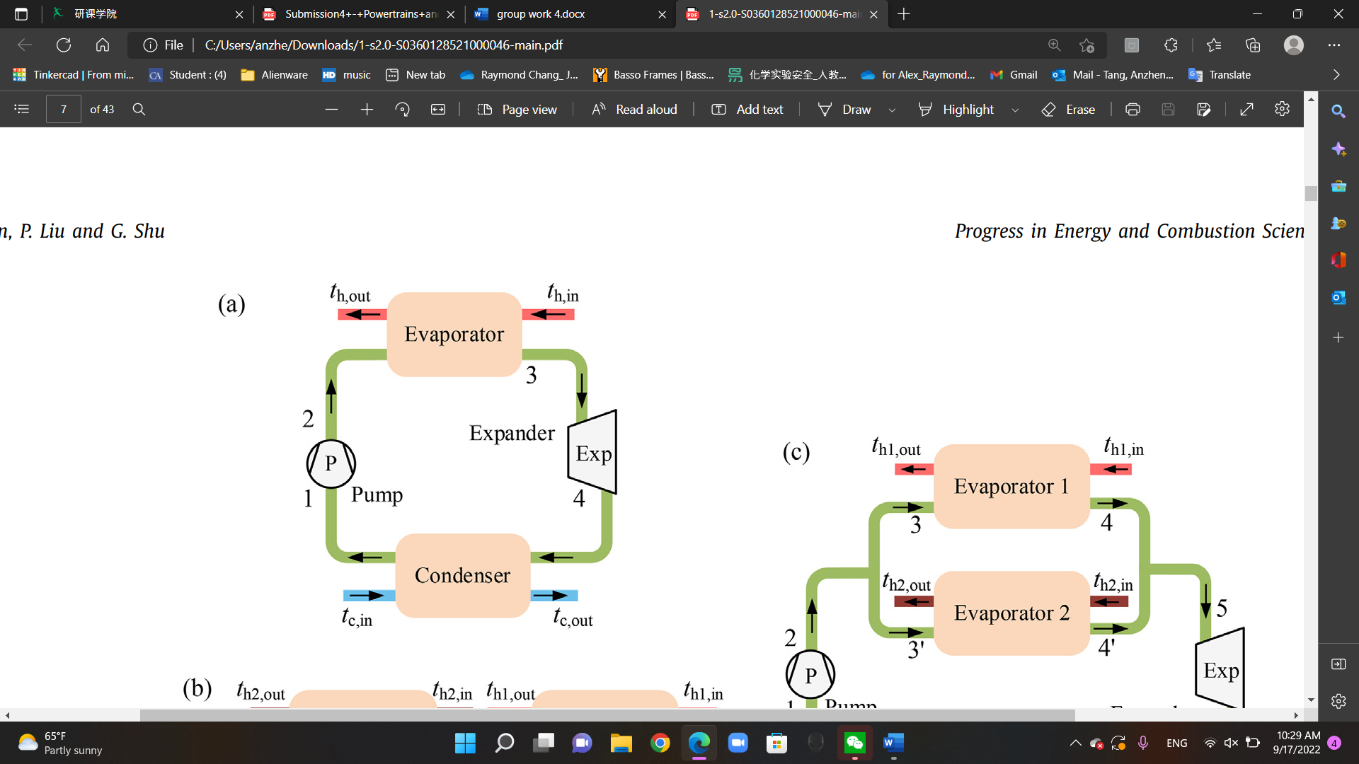
Figure 1 shows a diagram of the basic structure of RC [8]
The advantage of this energy recovery system is that it can be connected to the engine's coolant fluid. In that case, this system can recycle the thermal energy lost in the exhaust system and the energy lost in the engine, which significantly improves fuel efficiency [9]. However, this burdensome system's giant size and substantial weight make it only suitable for heavy-duty automobiles.
Using power turbines to extract additional energy from the exhaust gas is known as turbo compensation. Various mechanical turbochargers have been used in commercial engines to boost performance and improve fuel efficiency. With the modern electrification of automobiles, new turbochargers are introduced to the market. Among those developments, one of the most promising technologies is Electrical Turbo Compound (ETC). ETC has a generator (or power turbine in some cases) that is integrated into, connected in series with, or placed parallel to the turbocharger. The power turbine recovers the kinetic energy lost in the exhaust system by converting the energy into electricity and storing it in a battery. For the integrated ETC (meaning the generator is integrated into the turbocharger), a generator motor is integrated into the turbocharger shaft. Therefore, the generator would be driven when the turbine and the turbocharger compressor start spinning. Because of its capability to vary the amount of power extracted from the exhaust gas, this arrangement provides additional control flexibility. Nonetheless, this arrangement is more suitable for massive engines.
The inline turbocharger, in which the power turbine in series has both a turbocharger turbine and an electric generator, is called ETC in series, also known as sequential ETC.
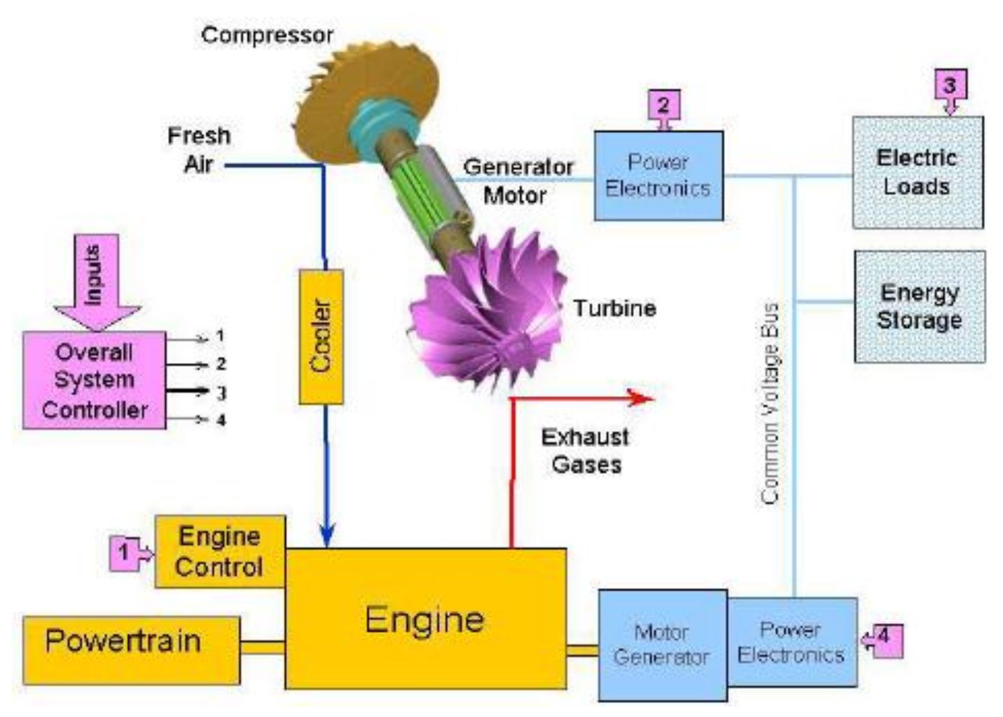
Figure 2 shows the working principle of sequential ETC, aka ETC series [10]
It is one of the basic configurations in heavy-duty engines. The technology can provide a few percent efficiency gains, but these gains can be increased by Exhaust Gas Recirculation (EGR), which diverts airflow away from the power turbine. That is to say, a series ETC contains a standard turbo (or turbos) and a generator simultaneously, which is used to recover the energy that has been discharged. Thanks to the sequential structure, vehicles that use this kind of ETC have advantages in reducing the turbo lag, improving the throttle response, creating an environment that allows a smoother delivery of the power, and allowing some tuning potential. However, as a sacrifice, it is more expensive, less reliable, and has less tuning potential compared with single or parallel turbos. As the beginning of this paragraph said, the sequential ETC (ETC in series) is more suitable on heavy-duty trucks or more powerful boats due to its complexity and size. As a result, the turbo lag is about 30% shorter than that of cars, and the generator can also be fully utilized because of the sufficient supply of the sucked-in water that passes through the turbo of a yacht. Two-stroke low-speed diesel engine is widely employed in the marine industry thanks to their evident advantages in fuel economy and reliability. Typically, a turbocharger and an auxiliary air blower are employed in the two-stroke engine to ensure smooth scavenging over whole propeller characteristics. However, fuel economy and layout compactness of the engine are scarified due to the employment of the auxiliary device [11]. In short, to some extent, the bigger the carrier or the displacement of its engine is, the better it can release the potential of sequential ETC.
Electric turbo compound (ETC) may also be connected in a parallel position. Compared to the in-series position, the exhaust gas from the engine would first go through two throttles, which control whether the exhaust gas flows over the turbocharger or the power turbine. Parallel turbochargers are appropriate when the exhaust energy exceeds the turbocharger's energy requirements and the turbocharger must be bypassed. Also, in order to increase the flexibility, a variable nozzle turbocharger (VNT) can be applied in the electric turbo compound (ETC) system, the power turbine can be driven by a variable nozzle turbocharger (VNT), and one of the throttles can be removed. The throttle can either be closed or opened to transfer all the energy to the turbo or the power turbine, depending on different conditions.
2. Discussion
To step further into the comparison between different energy recovery systems (ERS) applied in hybrid vehicles, a hypothesis needs to be established. Here, for the sake of simplicity, it is assumed that the combustion engines those energy recovery technologies apply to are the same.
2.1Thermoelectric
To achieve energy recovery and fuel efficiency during the operation of vehicles, Thermoelectric Energy Recovery System (TERS) is designed to convert some of the waste heat energy into electricity which can be further supplied to the battery and the electric motor. According to scientific research, about 40% of the engine's energy is lost through exhaust gas heat [1], even in a highly efficient, state-of-the-art internal combustion engine. Therefore, it can be deduced that the vehicle performance will increase to a much higher level if the exhaust gas can be utilized to a greater extent.
A more detailed, specific configuration of the thermoelectric energy recovery system is proposed in the discussion section. In this paper, a modeled extended-range electric vehicle with a simple external combustion Thermoelectric Generator (TEG)-Auxiliary Power Unit (APU) is reviewed and analyzed [3]. The system consists of three main components: the combustion compartment, the TEG module, and a battery connected to the electric motor. The exhaust gas is passed through the combustion chamber blower, followed by the combustion chamber at first. They are then transferred to the exhaust gas heat exchanger, which transfers heat between a source and a working fluid [3]. After that, heat enters the TEG module, consisting of a hot reservoir and a cold one on each end, with thermoelectric materials between the two ends. The materials used are usually good electrical conductors and poor thermal conductors. As a result, semiconductors are considered a good option when selecting materials [4]. During the process in the TEG module, the temperature difference between the hot and cold ends generates a direct current in the TEG module.
The working principle is based on the Seebeck Effect: an electromotive force is developed across two points of an electrically conducting material when there is a temperature difference between them. The potential difference generated is directly proportional to the temperature difference between the two ends. Therefore, the reason why the performance of the TEG ERS system largely depends on the temperature of the exhaust gas is explained. A thermocouple is also used to measure the potential difference across the material's two ends. Finally, the cold reservoir exchanges heat through the cold HEX with the ambient air [3]. The ambient air is slightly heated and, therefore, can aid the electric heater when necessary. The DC generated in the APU is transferred to the battery in the next step.
The battery, connected in series with the DC/AC converter and the electric motor, will therefore be charged. The battery transfers electricity to the DC/AC converter when extra power is needed. The converter will pass on the electricity to the electric motor. The motor finally drives the rear wheel. An APU controller takes charge of the APU system, and it will decide whether to switch on or off the system according to the battery's SOC (state of charge). In general, the recovery process usually occurs during the vehicle's braking phase. When this happens, the hydraulic brake commands installed at the rear-wheel shaft of the vehicle send signals to the vehicle controller to request energy recovery. The APU Controller then triggers the system, and energy is recovered. Notice that the system will be shut down in other driving circumstances for energy saving since it still consumes energy when it is not working.
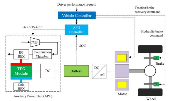
Figure 3 shows the configuration of an HEV equipped with Thermoelectric ERS [1]
The content above depicted a detailed description of the configuration and working principles of a TEG-APU installed in an extended-range electric vehicle. The primary benefits and challenges are analyzed based on the information above. Firstly, as mentioned in the introduction: this technology is based on solid-state constructions. The modules between the two ends are made of solid, fixed materials which do not rely on gases or vacuum [5]. This ensures durability during extreme conditions like cracking, shattering, and other turbulent circumstances. More importantly, the technology has proved itself in the extreme and zero range of gravitational forces [12]. As a result, it has a long history in aerospace due to its robustness in extreme environments in space. A second advantage is that the configuration of a TEG is relatively simple compared to other ERS technologies [6]. The APU system only consists of the combustion compartment, the TEG module, and a battery, which is much simpler than the ERS using Rankine Cycle (See the Rankine Cycle Part).
The drawbacks are also apparent, given that the cost of TEG materials is relatively high. Currently, materials that combine the nature of acceptable prices and ideal performances do not exist [5]. Consequently, the range of materials available for testing is sadly rare due to their expense. According to the University of the Pacific, a single thermoelectric module producing 14 watts of electrical power costs approximately 65 pounds. This is the first challenge encountered by researchers who aim to propagate this technology into passenger cars. Secondly, the TEG itself adds a considerable amount of weight to HEV. The materials used to construct HEV tend to be heavy, a trade-off of cheapness and optimum energy performance. Although it is common knowledge that EVs and HEVs have already suffered from the overweight of batteries, the challenges brought by the imposition of TEGs will outweigh the fuel saving it brings. This is mainly because the most widely used thermoelectric materials are weighty. Also, given that the TEG system is based on solid-state configurations, it has sacrificed its compactness for more durable performance. A third drawback is that backpressure will be produced on the internal combustion engine due to TEG integration in the exhaust line [5]. Past research shows that the engine power loss of backpressure increases as the number of rows of the TEG module increases and the number of columns decreases [3].
Last but not least, the system's performance tends to fluctuate fiercely, corresponding to the temperature. To be more detailed, the system's efficiency cannot be guaranteed with an uneven temperature distribution on the generator. This is a sign of instability which is not welcomed during driving circumstances like urban roads. Cars on urban roads during rush hours must stop from time to time, and it is admittedly recognized that the working temperature cannot be maintained at a certain level.
Suppose this technology is compared with ETC technology. In that case, the results will be disappointing as studies have compared the reduction of CO2 emissions achieved with the TEG and the ETC in two driving cycles. In Figure 4, referring to the NEDC, a decrease of CO2 of about 5% occurs for the vehicle equipped only with the ETC. The TEG implementation in the vehicle model exhibits lower savings, with a figure of only 1.9 % in fuel economy and CO2 reduction. In the NEDC, a reduction of CO2 emissions down to 5.6 % is achieved. The trend of the simulation results can be easily extended to WLTC as well. However, the performance of TEG (1.9%) is still worse than that of ETC (5.3%). Hence, it can be concluded that there is still much work to do with this technology, which is far from mature. Compared with ETC's affordability and light-weight configurations, thermoelectric ERS is not the best option for compact HEV. Meanwhile, because of its high requirement for stabilized working conditions, the technology may be more suitable for driving on highways than in normal driving conditions. However, it is still generally believed that this technology has great potential and may find its position in HEV powertrains shortly.
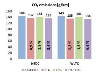
Figure 4 shows the estimated CO2 emissions along NEDC and WLTC [4]
2.1 Rankine Cycle
Besides thermoelectric, Rankine Cycle is another way to recycle thermal energy lost in the exhaust system of an ICE (internal combustion engine). Let the high-temperature exhaust gas go through an evaporator, turning fluid into a vapor. Then, the vapor pushes an expander, turning the mechanical energy into electricity. The vapor would subsequently enter a condenser, turning it into liquid again. Afterward, the pressure of the liquid is raised again by a pump, which pushes the fluid back into the evaporator.
Rankine cycle (RC) has a unique advantage: It can recycle the heat lost from the exhaust gas and engine fluids by adding another evaporator into the RC system. According to previous research [7], the combined thermal energy recovery can achieve a desirable performance with fuel savings of up to 10%. Moreover, due to the lower compression ratio, gasoline ICEs have a higher exhaust gas and engine fluid temperature than diesel ICEs [9,13], which means the RC would be more suitable for gasoline ICEs. Since Gasoline ICEs are more common on the market nowadays, the future application of RC is very promising.
The RC has some drawbacks, however. It increases ICE's backpressure and increases the weight of the vehicle. RC complicates the exhaust system as the exhaust gas must go through the evaporator. This additional path increases the engine's backpressure, resulting in a loss of horsepower and an increase in fuel consumption. It is proven that the area of the evaporator is proportional to the back pressure introduced [9]. By El Chammas and Clodic’s research [10], if an organic RC system is introduced to a gasoline ICE, the increased back pressure could cause up to 2.5% horsepower loss at high loads the increased back pressure could cause up to 2.5% horsepower loss at high loads.
Meanwhile, because there are four essential components in the RC system, the system usually weighs a lot, which increases fuel consumption too. Di Battista claims that if a 50kg RC system is installed on a 3350 kg light-duty vehicle, one should expect a fuel consumption increase of 1% [11]. These drawbacks suggest that the RC system is probable not suitable for urban driving vehicles that handle a lot of acceleration and deceleration.
2.3 Integrated Electric Compound
Integrated electric turbo compound integrates a turbo compound turbine, a centripetal compressor, and an electric motor generator over a planetary gearset. It is mechanically connected to the engine crankshaft via a clutch. By controlling the clutch to the crankshaft and the compressor break, the system can be operated in 4 different modes. In mode A, the clutch is opened, and the compressor is fixed. Then, the system operates in electric turbo compound mode.
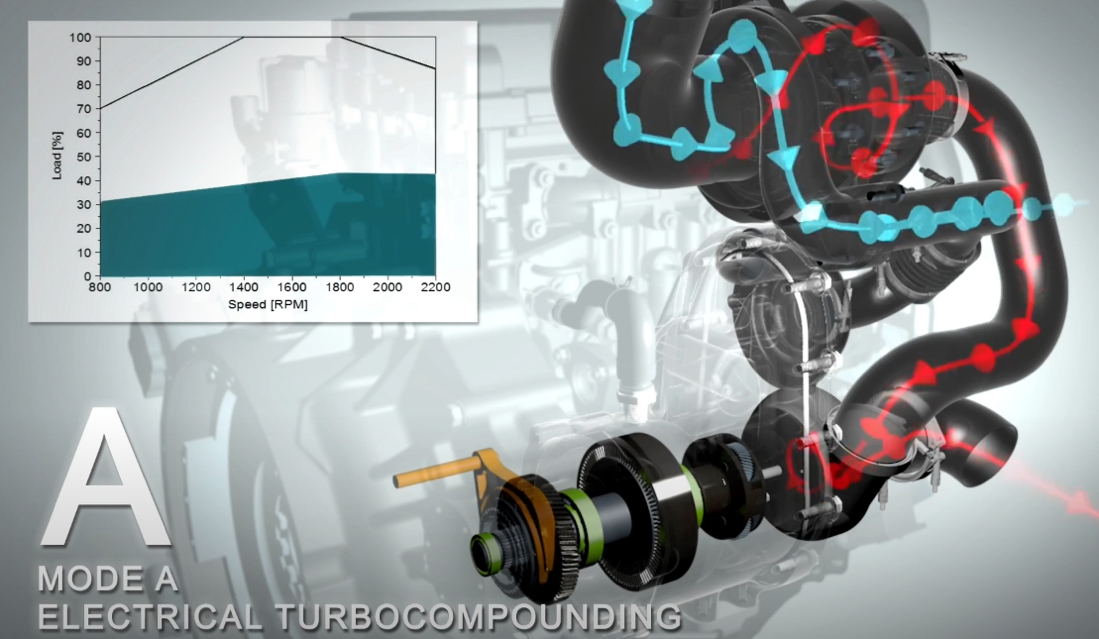
Figure 5. shows the mode A [14]
In mode B, the clutch to the crankshaft is closed, and the compressor is still fixed. The system becomes a mechanical turbo compound system with the addition of mild hybrid capability through the motor generator. Electrical torque assist or battery charging is possible in this mode.
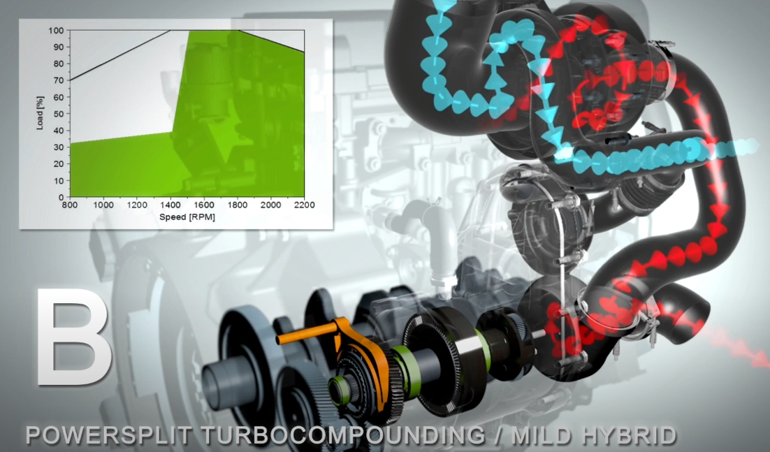
Figure 6 shows the mode B [14]
In mode C, the clutch is open, and the compressor is driven by the turbo compound turbine with the ability of electrical assist.
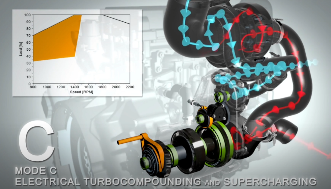
Figure 7 shows the mode C [14]
In mode D, the clutch is closed, and the compressor is driven mechanically from the crankshaft.
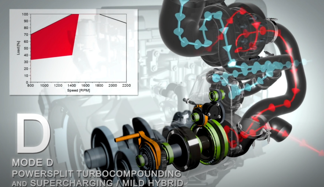
Figure 8 shows the mode D [14]
Mode C and mode D provide a second-stage boosting system making the system an ideal solution for high low torque requirements of downsized or down speed engines. There is an assumption of a 15% economy improvement for a medium-duty truck with a downsized engine.[15] This engine is still hard to produce (the cost is relatively high). The size of this system is also big since it contains a motor generator, a battery, and a turbocharger.
2.4 ETC in Series
ETC in series, also known as the sequential ETC or the in-series ETC, is one of the most important and the most efficient methods of ERS. The structure is complicated by forming a series of connections between the turbo and an electric generator. However, how it saves energy is almost the same as those regular turbos. Therefore, ETC in series can be vaguely considered as turbo(s) working with a generator at the same time. As a result, the sequential ETC can increase the fuel economy and store some of the electricity in the batteries, which can be used as a power source to drive a car or provide power for air conditioners and other electrical appliances. In this way, in-series ETC does two different things, saving fuel and generating electricity simultaneously, which contributes to a highly high efficiency compared with others.
The disadvantages are also quite conspicuous. Because of the profound volume of the sequential ETC, it is hard for a sequential turbo to release all its potential without a big engine. In addition, the complexity of the structure is a significant issue for using this technology in a compacted urban vehicle. The room is limited if we need to put the sequential ETC in a compact car. As a result, we need to produce smaller parts to adapt to a smaller size. With smaller parts being produced, reliability becomes an issue because the parts must be more precisely made. Otherwise, a mechanic failure might occur. Also, the potential of the in-series ETC may not be as significant as the one used for heavy-duty ones due to its smaller size.
Results show that adopting ETC is not advantageous if used for a conventional turbocharger turbine if the target is to optimize the overall efficiency in one specific operating point of the ICE, like in the case of range-extended electric vehicles. Besides, ETC can slightly improve the average overall efficiency when the ICE must provide variable power output, as in the case of conventional or hybrid vehicles. However, the significant benefits coming from ETC are the boost range extension in the lowest engine rotational speed region and a possible reduction of turbo lag, which are critical points in parallel-hybrid and especially in conventional vehicles [16].
In the EBTG system, the turbo and compressor operate independently. Its impact on a gasoline engine was analyzed from the perspective of fuel economy, power output, availability distribution, and transient performance. Results show that the proposed EBTG system effectively improves the engine's thermal efficiency at high-speed and wide-open throttle conditions. Simultaneously, it is also valuable to solve the engine's turbo lag. Applying the EBTG system, the maximum reduction of specific fuel consumption was 2.6%. Exergy analysis showed that the EBTG system could reduce the turbine's irreversibility and recover more exergy from exhausts. There was a 0.8 percentage point exergy efficiency increment at 4400 rpm and full-load operation. The step response time of boost pressure in the EBTG engine decreased to about half of it in baseline at 2000 rpm and full-load condition. Explains why before the discovery of HEV automobiles, the structure of sequential ETC already appeared on boats and even in small planes [13].
The future vision of ETC in series is to compress its size and simplify the structure to ensure reliability, which is also the most significant problem for sequential ETC equipped in compact urban used cars.
2.5 ETC in Parallel
An electric turbo compound in parallel is a power turbine in series with a turbocharger connected parallel with the power turbine, allowing the engine's exhaust gas to flow in two directions to provide extra energy to the vehicle.
The main advantage of the electric turbo compound connected in parallel is its flexibility. Comparing to an electric turbo compound (ETC) in series, an electric turbo compound connected in parallel decide where the exhaust gas goes. Some electric turbo compounds are connected with a fixed geometry turbine (FGT) system. [17] This system has two throttles, one of which can be either fully closed or fully open, to determine whether the gas is delivered to the power turbine or the turbo.
The turbo turbine of the electric turbo compound connected in parallel can also combine with a variable nozzle turbocharger. Adding a variable turbo nozzle into the parallel electric turbo compound can increase the flexibility of the energy recovery, which would vastly decrease the energy loss during the process. A variable nozzle turbocharger (VNT) is a type of turbocharger that can alter the ratio that flows through the turbine by the lines; it enables the turbocharger to increase the boost by alternating the aspect ratio to let the turbo maintain its best condition.
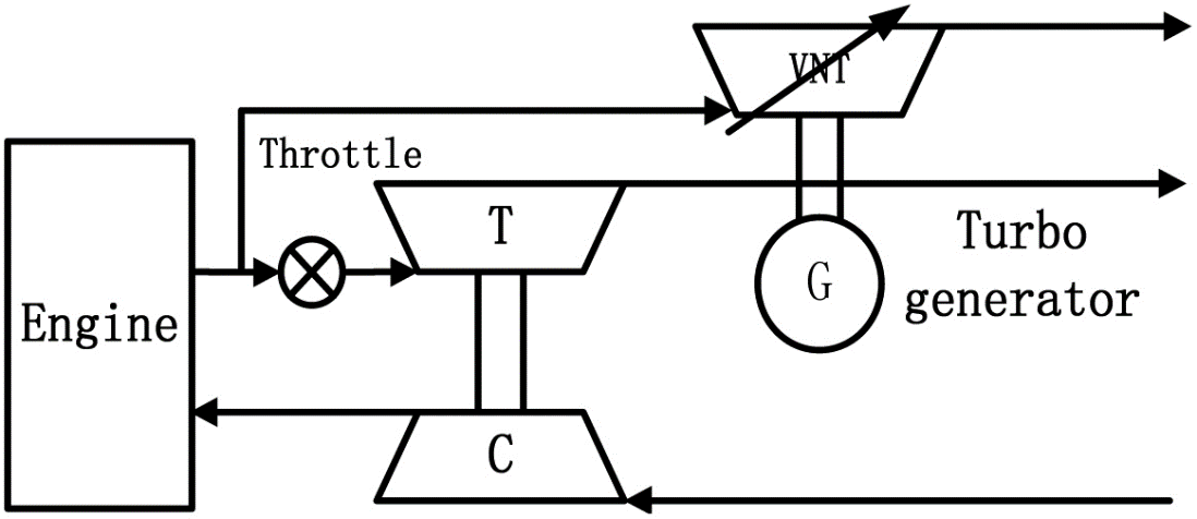
Figure 9 shows the ETC system with VNT [17]
By adding a variable nozzle turbocharger, the ratio of the gas flow to the power turbine and the turbocharger can be varied; when the car is at high load operating conditions, the variable nozzle turbocharger (VNT) would be closed to ensure that the exhaust gas to flow through the turbocharger turbine to create more power mainly on the engine. [17] While the engine is in low-load operating conditions, the variable turbocharger would be partly or wholly closed to let the power turbine create more electricity.
However, although parallel connected electric turbo compound (ETC) would improve the efficiency when the engine is at high load working conditions, the fuel economy is not significantly improved under normal conditions. Furthermore, the throttles of the parallel electric turbo compound (ETC) also need to be manufactured with care since the exhaust's high temperature may make the throttles stuck due to thermal expansion.
2.6. Summary
As a result, thermoelectric has the advantage of having a simple structure for thermal energy recovery. However, it is expensive to build and adds much extra weight to the vehicle. The Rankine Cycle can recycle heat from the exhaust gas and engine coolants, but it also increases the vehicle's weight and introduces a loss in the power output. On the other hand, for kinetic energy recovery, integrated ETC provides a variety of operation modes to suit different circumstances. In-series ETC has a more straightforward structure, making it more reliable, but it requires a large room; parallel ETC can deliver more power if a VNT is installed.
3 Conclusion
After detailed reviews and analysis, it can be concluded that Thermoelectric Energy Recovery System is less suitable for hybrid electric vehicles than other types of ERS. Although the technology is well-known for being durable and simple, the current challenges still outweigh the advantages and prevent the technology from massive applications in compact HEVs. Issues including the unaffordable cost of thermoelectric materials, the efficiency during fluctuating working circumstances, and the overweight of TEG need different resolutions in the future. Currently, the technology is more developed in aerospace than in HEV since the effect of being overweight is less considered in outer space. This also indicates that the technology is more suitable in large vehicles like trucks, tractors, and space shuttles than in ordinary HEV vehicles.
RC is a great way to recycle thermal energy. Nevertheless, it has a complicated structure that introduces excessive weight to the vehicle. In addition, the evaporator, a vital component of the RC, introduces a loss of power by increasing the backpressure of an ICE. These characters decide that the RC application is mainly on massive ships and heavy trucks or other powerful machinery with giant engines that have much weight either way. However, compact hybrid electric vehicles do not fit into this category. Compact HEVs are usually lighter; an RC's extra weight can significantly impact its operating performance. Urban driving vehicles handle more accelerations and decelerations. Under such conditions, the extra weight will enormously influence the handling ability and driving experience of compact HEVs. Moreover, compact HEVs typically have a small and, thus, less powerful engine that cannot afford a power loss. As a result, RC is unsuitable for compact hybrid electric vehicles used for urban driving.
Integrated electric turbo compound is suitable for hybrid vehicles due to the following advantages. First, it has four modes that can avoid power loss. It also has no impact on the driving experience because it can switch off the turbo to reduce the effect on acceleration. Furthermore, integrated ETC is relatively cheap to be made. Finally, this system is light, making it fuel-efficient in civilian cars. Light car is essential since these kinds of cars accelerate and decelerate a lot in urban area.
The advantages and disadvantages of sequential ETC are transparent compared with other methods. For its advantages, the sequential ETC has a higher potential than any other method mentioned above thanks to the electric generator that connects with the turbo, which can remarkably efficiently recover energy from electricity. As for the disadvantages, reasoning from the limitation of the great inertia of the electric generator that connects with the turbo, sequential ETC cannot wholly release its potential because if the displacement or the power of the engine is too little, there will not be enough air or fluid to drive the generator and meanwhile the efficiency of the turbo is also decreased.
The parallel-connected electric turbo compound is best known for its flexibility, which allows the power turbine to convert the exhaust gas to energy to power the vehicle. However, as we can see, the disadvantages of the structure still outweigh the advantages of a hybrid electric vehicle. In addition, designing and manufacturing the throttles would be difficult. Finally, the fuel economy while the engine works under normal conditions is not as significant as working under heavy load conditions, which does not apply to daily-use vehicles.
Finally, by the size, weight, cost, and efficiency of each energy recovery system introduced above, the integrated ETC is the best option for compact hybrid electric vehicles used for urban driving.
4 Acknowledgment
Zirui Fang, Shitong Nian, and Anzheng Tang contributed equally to this work and should be considered co-first authors. Meanwhile, Xinran Yu contributed equally to this work and should be considered co-second authors.
References
[1]. W. Bou Nader, "Thermoelectric generator optimization for hybrid electric vehicles," Applied Thermal Engineering, vol. 167, p. 114761, 2020/02/25/ 2020, doi: https://doi.org/10.1016/j.applthermaleng.2019.114761.
[2]. J. Hagman and J. J. Stier, "Selling electric vehicles: Experiences from vehicle salespeople in Sweden," Research in Transportation Business & Management, p. 100882, 2022/09/02/ 2022, doi: https://doi.org/10.1016/j.rtbm.2022.100882.
[3]. S. Lan, R. Stobart, and X. Wang, "Matching and optimization for a thermoelectric generator applied in an extended-range electric vehicle for waste heat recovery," Applied Energy, vol. 313, p. 118783, 2022/05/01/ 2022, doi: https://doi.org/10.1016/j.apenergy.2022.118783.
[4]. I. Arsie, A. Cricchio, C. Pianese, V. Ricciardi, and M. De Cesare, "Modeling Analysis of Waste Heat Recovery via Thermo-Electric Generator and Electric Turbo-Compound for CO2 Reduction in Automotive SI Engines," Energy Procedia, vol. 82, pp. 81-88, 2015/12/01/ 2015, doi: https://doi.org/10.1016/j.egypro.2015.11.886.
[5]. J. Liebl, S. Neugebauer, A. Eder, M. Linde, B. Mazar, and W. Stütz, "The thermoelectric generator from BMW is making use of waste heat," MTZ worldwide, vol. 70, no. 4, pp. 4-11, 2009/04/01 2009, doi: 10.1007/BF03226939.
[6]. F. Ji et al., "Experimental and numerical investigation on micro gas turbine as a range extender for electric vehicle," Applied Thermal Engineering, vol. 173, p. 115236, 2020/06/05/ 2020, doi: https://doi.org/10.1016/j.applthermaleng.2020.115236.
[7]. U.G.E. Birkholz, U. Stohrer, K. Voss, Conversion of waste exhaust heat in auto- mobiles using FeSi2. thermoelements. Proceedings of the 7th International Conference on Thermoelectric Energy Conversion. 1988.
[8]. H. Tian, P. Liu, and G. Shu, “Challenges and opportunities of Rankine cycle for waste heat recovery from internal combustion engine,” Progress in Energy and Combustion Science, vol. 84, p. 100906, May 2021, doi: 10.1016/j.pecs.2021.100906.
[9]. G. Shu, G. Yu, H. Tian, H. Wei, X. Liang, and Z. Huang, “Multi-approach evaluations of a cascade-Organic Rankine Cycle (C-ORC) system driven by diesel engine waste heat: Part A – Thermodynamic evaluations,” Energy Conversion and Management, vol. 108, pp. 579–595, Jan. 2016, doi: 10.1016/j.enconman.2015.10.084
[10]. W. Zhuge, L. Huang, W. Wei, Y. Zhang, and Y. He, "Optimization of an Electric Turbo Compounding System for Gasoline Engine Exhaust Energy Recovery," SAE Technical Papers, 04/12 2011, doi: 10.4271/2011-01-0377.
[11]. D. Zi, L. Zhang, B. Chen, and Q. Zhang, "Study of the electric-booster and turbo-generator system and its influence on a 1.5 L gasoline engine," Applied Thermal Engineering, vol. 162, p. 114236, 2019/11/05/ 2019, doi: https://doi.org/10.1016/j.applthermaleng.2019.114236.
[12]. Benefits of Thermoelectric Technology for the Automobile, Francis Stabler.General Motors & Future Tech LLC 2011 DOE Thermoelectric Workshop San Diego,CA[Online]. Available: https://www.energy.gov/sites/prod/files/2014/03/f13/stabler.pdf
[13]. M. Kadota and K. Yamamoto, “Advanced Transient Simulation on Hybrid Vehicle Using Rankine Cycle System,” SAE International Journal of Engines, vol. 1, no. 1, pp. 240–247, Apr. 2008, doi: 10.4271/2008-01-0310
[14]. FEV Group, ITES-Integrated TurboCompounding/WHR electrification and supercharging. (Nov.7,2018). Accessed: Sep.17, 2022. [Online Video].Available:https://www.youtube.com/watch?v=exfKr94PgDI
[15]. M. Yang et al., "Matching method of electric turbo compound for two-stroke low-speed marine diesel engine," Applied Thermal Engineering, vol. 158, p. 113752, 2019/07/25/ 2019, doi: https://doi.org/10.1016/j.applthermaleng.2019.113752
[16]. M. Algrain, "Controlling an electric turbo compound system for exhaust gas energy recovery in a diesel engine," in 2005 IEEE International Conference on Electro Information Technology, 22-25 May 2005, 2005, pp. 6 pp. 6, doi: 10.1109/EIT.2005.1627004.
[17]. G. Pasini et al., "Evaluation of an electric turbo compound system for SI engines: A numerical approach," Applied Energy, vol. 162, pp. 527-540, 2016/01/15/ 2016, doi: https://doi.org/10.1016/j.apenergy.2015.10.143.
Cite this article
Fang,Z.;Nian,S.;Tang,A.;Yu,X. (2023). A comparison of energy recovery systems using exhaust gases in hybrid electric vehicles. Applied and Computational Engineering,7,534-545.
Data availability
The datasets used and/or analyzed during the current study will be available from the authors upon reasonable request.
Disclaimer/Publisher's Note
The statements, opinions and data contained in all publications are solely those of the individual author(s) and contributor(s) and not of EWA Publishing and/or the editor(s). EWA Publishing and/or the editor(s) disclaim responsibility for any injury to people or property resulting from any ideas, methods, instructions or products referred to in the content.
About volume
Volume title: Proceedings of the 3rd International Conference on Materials Chemistry and Environmental Engineering (CONF-MCEE 2023), Part II
© 2024 by the author(s). Licensee EWA Publishing, Oxford, UK. This article is an open access article distributed under the terms and
conditions of the Creative Commons Attribution (CC BY) license. Authors who
publish this series agree to the following terms:
1. Authors retain copyright and grant the series right of first publication with the work simultaneously licensed under a Creative Commons
Attribution License that allows others to share the work with an acknowledgment of the work's authorship and initial publication in this
series.
2. Authors are able to enter into separate, additional contractual arrangements for the non-exclusive distribution of the series's published
version of the work (e.g., post it to an institutional repository or publish it in a book), with an acknowledgment of its initial
publication in this series.
3. Authors are permitted and encouraged to post their work online (e.g., in institutional repositories or on their website) prior to and
during the submission process, as it can lead to productive exchanges, as well as earlier and greater citation of published work (See
Open access policy for details).
References
[1]. W. Bou Nader, "Thermoelectric generator optimization for hybrid electric vehicles," Applied Thermal Engineering, vol. 167, p. 114761, 2020/02/25/ 2020, doi: https://doi.org/10.1016/j.applthermaleng.2019.114761.
[2]. J. Hagman and J. J. Stier, "Selling electric vehicles: Experiences from vehicle salespeople in Sweden," Research in Transportation Business & Management, p. 100882, 2022/09/02/ 2022, doi: https://doi.org/10.1016/j.rtbm.2022.100882.
[3]. S. Lan, R. Stobart, and X. Wang, "Matching and optimization for a thermoelectric generator applied in an extended-range electric vehicle for waste heat recovery," Applied Energy, vol. 313, p. 118783, 2022/05/01/ 2022, doi: https://doi.org/10.1016/j.apenergy.2022.118783.
[4]. I. Arsie, A. Cricchio, C. Pianese, V. Ricciardi, and M. De Cesare, "Modeling Analysis of Waste Heat Recovery via Thermo-Electric Generator and Electric Turbo-Compound for CO2 Reduction in Automotive SI Engines," Energy Procedia, vol. 82, pp. 81-88, 2015/12/01/ 2015, doi: https://doi.org/10.1016/j.egypro.2015.11.886.
[5]. J. Liebl, S. Neugebauer, A. Eder, M. Linde, B. Mazar, and W. Stütz, "The thermoelectric generator from BMW is making use of waste heat," MTZ worldwide, vol. 70, no. 4, pp. 4-11, 2009/04/01 2009, doi: 10.1007/BF03226939.
[6]. F. Ji et al., "Experimental and numerical investigation on micro gas turbine as a range extender for electric vehicle," Applied Thermal Engineering, vol. 173, p. 115236, 2020/06/05/ 2020, doi: https://doi.org/10.1016/j.applthermaleng.2020.115236.
[7]. U.G.E. Birkholz, U. Stohrer, K. Voss, Conversion of waste exhaust heat in auto- mobiles using FeSi2. thermoelements. Proceedings of the 7th International Conference on Thermoelectric Energy Conversion. 1988.
[8]. H. Tian, P. Liu, and G. Shu, “Challenges and opportunities of Rankine cycle for waste heat recovery from internal combustion engine,” Progress in Energy and Combustion Science, vol. 84, p. 100906, May 2021, doi: 10.1016/j.pecs.2021.100906.
[9]. G. Shu, G. Yu, H. Tian, H. Wei, X. Liang, and Z. Huang, “Multi-approach evaluations of a cascade-Organic Rankine Cycle (C-ORC) system driven by diesel engine waste heat: Part A – Thermodynamic evaluations,” Energy Conversion and Management, vol. 108, pp. 579–595, Jan. 2016, doi: 10.1016/j.enconman.2015.10.084
[10]. W. Zhuge, L. Huang, W. Wei, Y. Zhang, and Y. He, "Optimization of an Electric Turbo Compounding System for Gasoline Engine Exhaust Energy Recovery," SAE Technical Papers, 04/12 2011, doi: 10.4271/2011-01-0377.
[11]. D. Zi, L. Zhang, B. Chen, and Q. Zhang, "Study of the electric-booster and turbo-generator system and its influence on a 1.5 L gasoline engine," Applied Thermal Engineering, vol. 162, p. 114236, 2019/11/05/ 2019, doi: https://doi.org/10.1016/j.applthermaleng.2019.114236.
[12]. Benefits of Thermoelectric Technology for the Automobile, Francis Stabler.General Motors & Future Tech LLC 2011 DOE Thermoelectric Workshop San Diego,CA[Online]. Available: https://www.energy.gov/sites/prod/files/2014/03/f13/stabler.pdf
[13]. M. Kadota and K. Yamamoto, “Advanced Transient Simulation on Hybrid Vehicle Using Rankine Cycle System,” SAE International Journal of Engines, vol. 1, no. 1, pp. 240–247, Apr. 2008, doi: 10.4271/2008-01-0310
[14]. FEV Group, ITES-Integrated TurboCompounding/WHR electrification and supercharging. (Nov.7,2018). Accessed: Sep.17, 2022. [Online Video].Available:https://www.youtube.com/watch?v=exfKr94PgDI
[15]. M. Yang et al., "Matching method of electric turbo compound for two-stroke low-speed marine diesel engine," Applied Thermal Engineering, vol. 158, p. 113752, 2019/07/25/ 2019, doi: https://doi.org/10.1016/j.applthermaleng.2019.113752
[16]. M. Algrain, "Controlling an electric turbo compound system for exhaust gas energy recovery in a diesel engine," in 2005 IEEE International Conference on Electro Information Technology, 22-25 May 2005, 2005, pp. 6 pp. 6, doi: 10.1109/EIT.2005.1627004.
[17]. G. Pasini et al., "Evaluation of an electric turbo compound system for SI engines: A numerical approach," Applied Energy, vol. 162, pp. 527-540, 2016/01/15/ 2016, doi: https://doi.org/10.1016/j.apenergy.2015.10.143.