


1. Introduction
UAV technology has been widely developed and applied in recent years. With the aim of applying for the military, this unmanned vehicle has a more extensive and significant position in the modernization of national defence and the army, such as reconnaissance, surveillance, and combat [1]. At the same time, UAVs are also developing rapidly in the civilian field. UAV companies led by DJI have launched a large number of civilian UAV products, which are widely used in photography, mapping, rescue, inspection, search, agriculture, and so forth. Generally speaking, unmanned aerial vehicle (UAV) is an advanced mechanism with great value and huge development potential, which has attracted the attention of various fields. However, with the development of traditional UAVs up to now, the defects caused by structural design tend to unfold over time. Traditional UAVs mainly fall into the following two types: rotorcraft UAV and fixed-wing UAV, which have various applications in different fields according to their own characteristics.
Therefore, a new design called Hybrid Vertical Take-off and Landing (VOLT) UAV has been proposed, which combines the vertical take-off and landing capabilities of rotary-wing UAVs and retains the long-endurance advantages of fixed-wing UAVs, and quickly attracted the attention of the academic community [2]. The rotor can carry out vertical take-off and hovering in the horizontal direction. This way of advancing by adjusting the direction of the wings instead of the direction of the fuselage can improve flight efficiency, but at the same time, the complex structure will inevitably increase the weight of the fuselage. It seems that the advantages of drone are not obvious.
Slant-rotor UAVs are a type of UAVs that meet the hybrid VOLT functions [3]. The UAV uses two independent propulsion systems, one for vertical flight and another for cruise flight [4]. There is no complex control strategy required during the transition from vertical flight to cruising flight, the dual-system UAV has robust control capability, and it is easy to take off and land. However, the inactivity of the dynamic system for cruise during VTOL system operation increases the overall weight of the aircraft for take-off and therefore reduces the efficiency of vertical flight. The UAV allows the two systems to share the same wing, which can be converted to each other, reducing the total mass of the aircraft [5]. However, the transition phase from vertical flight to cruise flight is very erratic. The calculation of flight dynamics and aerodynamics in the design of a rotating wing is too complicated. So far, only one aircraft design has successfully completed the transition flight [6].
Although the above different types of hybrid VTOL UAVs have solved some of the shortcomings of traditional UAVs to a certain extent and achieved the goal of balancing vertical take-off and landing functions with long endurance and high load. However, both conventional UAVs and hybrid VTOL UAVs still have a common problem, that is, they cannot take off and land smoothly in complex terrain conditions that are not flat (e.g., post-earthquake debris or mountainous terrain with harsh conditions).
In order to make a better landing on inclined or complex surfaces, several solutions have been proposed by some experts and scholars [7]. For example, using a planar dynamics model of a two-legged landing gear, a mechanical arm was added to the UAV fuselage for controlling and adjusting the height of the UAV kickstand in order to adapt to landing on complex terrain. Subsequently, simulation experiments were performed and the results were verified using mathematical and 3D models [8], [9].
Although the above model has good ground adaptability and flexibility, it significantly increases the overall UAV fuselage weight compared to fixed landing gear due to its more complex structure and control strategy, while the study favours stable adjustment of the UAV after landing and does not make more adjustments during the descent. And it is easy to slip and other situations in fragmented gravel terrain. Therefore, based on the DJI's UAV model (DJI F450/550 Landing Gear System V2), this paper improves the design of landing gear and kickstand, and designs a new landing strategy to achieve the optimal solution at the landing point [10].
The overall structure of the paper is shown below. Section 2 presents a detailed problem analysis for the landing system of DJI UAV. The structure of the adaptive landing system is analyzed and improved in Section 3. Section 4 simplifies the UAV model and completes the data analysis of the adaptive landing system at the same time. Section 5 designs an adaptive landing system algorithm that matches the above. Section 6 simulates the feasibility of landing a UAV in this environment using MATLAB. Section 7 concludes and outlooks the whole paper.
2. Problem analysis of landing system based on DJI UAV
2.1. Adaptive landing gear system process
Radar detection: The radar located underneath the UAV detects and collects ground information to obtain the height and terrain information of the ground [11].
Landing point calculation: Based on the terrain information obtained from the radar and the present landing point, the landing algorithm calculates the landing information and determines the location and altitude where the UAV needs to land.
Controller output: The landing algorithm transmits the calculated landing information to the controller. The controller outputs electrical signals according to the landing information, which are assigned to each linear actuator to control the landing gear and realize the UAV height control.
Adaptive adjustment: After the UAV descends vertically to a predetermined position, it makes adaptive adjustment according to the real-time road conditions. If other factors such as uneven ground or wind are found to interfere with the UAV landing, the landing algorithm will adjust the landing point in time, and the controller will adjust the height of the landing gear accordingly to ensure that the UAV lands smoothly at the designated position.
Landing completion: When the UAV lands at the predetermined position, the controller stops controlling the height of the landing gear and the UAV stops on the ground stably to complete the landing task.
2.2. DJI UAV reference model and problem analysis
According to the available information, DJI provides an available UAV model dji-f450-550-landing-gear-system-v2 (hereinafter referred to as the reference model) [10], in which part of the landing gear of the UAV adopts a liftable design. The overall structure of the UAV and the landing gear part are shown as in Figure 1 and Figure 2.
| ||
Figure 1. UAV model. (a) Front view; (b) Side view; (c) Vertical view. | ||
|
|
|
(a) | (b) | (c) |
Figure 2. Land gear. (a) Front view ;(b) Side view; (c) Vertical view. | ||
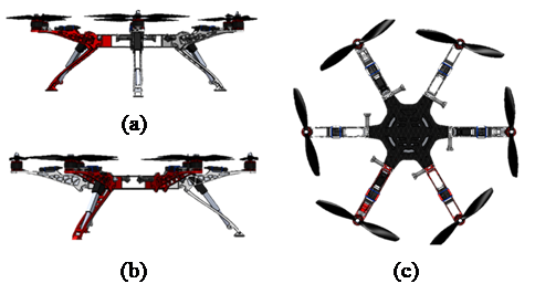
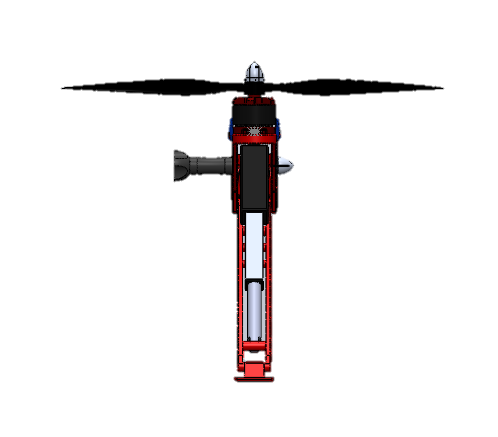
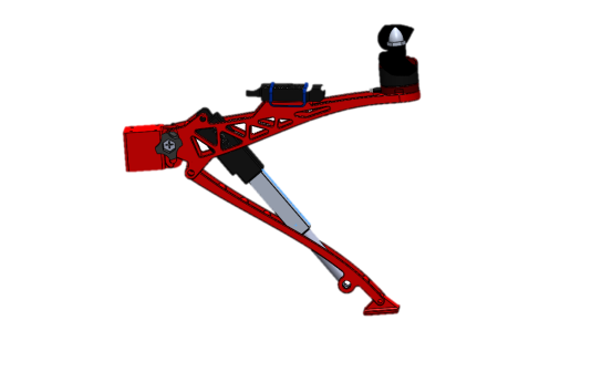
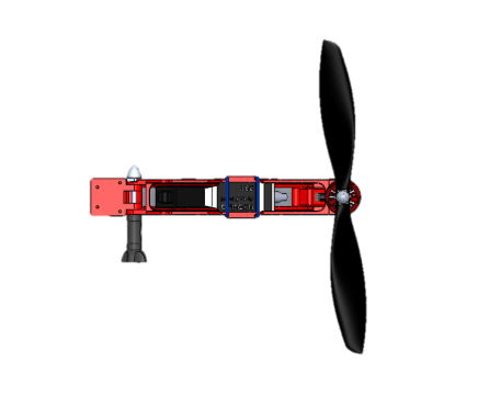
In the reference model, the landing gear is adjusted in height by a telescopic rod. The three landing gears of the reference model are designed to retract synchronously, which is intended to allow the landing gears to retract during flight. However, the stability of this structure is easily compromised when landing in complex field conditions.
Since the angle of the landing gear to the ground changes as the height of the landing gear is adjusted, the reference model simply keeps the foot in a state parallel to the ground at any angle. The design of the reference model UAV foot is a flat surface, which means that in the process of landing gear height adjustment, this flat surface will also no longer be parallel to the ground, and the contact surface between the UAV foot and the ground after landing is drastically reduced, and there is even a risk of losing balance causing the UAV to tip over. In the field environment often has tiny terrain undulations and more rocks, using a simple plane design will lead to the contact surface of the foot with the ground is not large enough to meet the stability of the complex terrain after falling. Therefore, this paper argues that the UAV landing environment capability can be improved by adjusting the landing gear co-drive to a separate landing gear drive. At the same time, for the problem of complex field environment terrain with more gravel and surface changes, the adaptive adjustment of UAV's complex environment adaptive capability can be greatly improved by adding an adaptive adjustable foot at the end of the landing gear.
3. Adaptive landing system structural analysis and improvement
3.1. UAV landing gear design
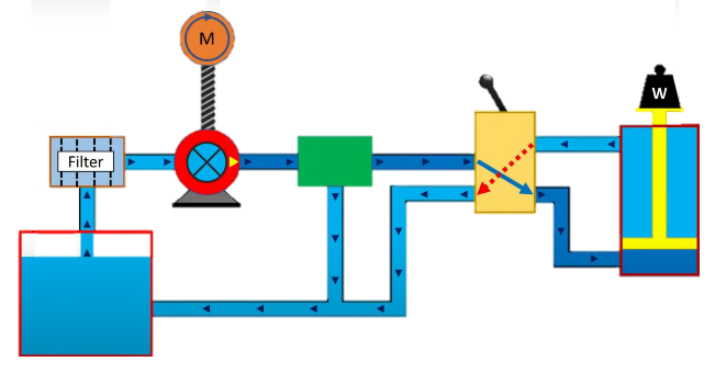
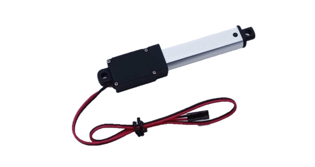
For the reference model, we improved the landing gear of the UAV to improve the UAV's ability to adapt to complex environments. First, in order to allow each landing gear of the UAV to control the height independently, we need to design a separate height adjustment device for each landing gear instead of the synchronous height control in the reference model. Next is the design choice of linear actuator. Hydraulic system is widely used in heavy-duty equipment because of its good stability and load capacity [12]. Since the object of this paper is a light-load UAV, the linear actuator is simpler and cheaper than the hydraulic control system and is more suitable for the landing gear height control of a light-load UAV. The diagram below shows the hydraulic system (Figure 3) and linear actuator (Figure 4) respectively [13].
|
|
Figure 3. Hydraulic system [14]. | Figure 4. Electric system [15]. |
3.2. UAV foot design
To make the UAV foot have enough traction on complex terrain with different angles [16], we designed two types of landing gears suitable for different environments. The first type of landing gear was designed to resemble the structure of a 3D carved needle. As shown in Figure 5.
|
|
(a) | (b) |
Figure 5. Foot structure. (a) Outside;(b) Inside. | |
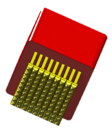
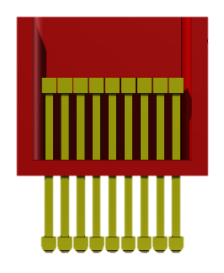
This design is characterized by several pins held in place by the foot shell and each pin can move freely up and down. The advantage of this design over the traditional flat design is that it can fit stably on almost any type of complex terrain, such as desert, gravel, mountains, ruins, etc. This allows the UAV's foot to achieve the maximum area of fit with the undulating ground, thus achieving stability. The disadvantage of this design is that the pins are not fixed, which means that even after landing, the pins are free to move, they just fit on the ground. Once impacted by the longitudinal external force, the pins will immediately stretch and change, resulting in the UAV's center of gravity shifting, which may lead to the risk of tipping over. Therefore, this paper designs another kind of foot with oil pressure cushion, whose structure schematic is shown in Figure 6.
|
|
|
(a) | (b) | (c) |
Figure 6. Oil pressure damping foot. (a) Outside;(b) Inside;(c) Assembling. | ||
The feature of this design is that each pin corresponds to a separate cylinder, and all cylinders are connected to each other through the oil circuit on the sealing cover. When the foot of the UAV touches the uneven ground, the pin that touches the ground first, i.e., the pin that touches the ground protrusion, will be slowly pushed back to the cylinder. The discharged oil is pushed into other cylinders with less pressure, pushing other pins out of the cylinder, thus touching the ground depression. This completes the adaptation to the complex ground shape during the landing process. In this foot design, the oil path between the cylinder and the seal cover is designed to be narrower for the following reasons.
1) So that the foot has a certain shock absorption function, cushioning the impact of the ground surface UAV foot.
2) The angle change is slow, which can make the UAV landing attitude control timely response, to ensure that the UAV does not fall over.
3) The foot shape will not change immediately when encountering large disturbances, so it can provide good grip.
The advantage of this design is that when the UAV encounters cross wind or shallow water flow disturbance because the direction of the external force is perpendicular to the pin, it does not change the elongation of the pin, so the pin embedded under the ground hooks the raised part of the ground, avoiding the risk of tipping of the UAV by shifting the center of gravity. The disadvantage of this design is that due to the low density of the pins, the adaptability to large debris or undulating terrain is poor, and the cylinder has a certain risk of oil leakage.
The above two types of foot can be adapted to different site requirements, but the corresponding cost is a complex structure, the risk of damage, and the weight of the UAV increases. Therefore, the foot is designed as a detachable articulated structure, which on the one hand can be easily replaced when the foot is damaged by aging, and on the other hand can be replaced with the original foot under normal terrain conditions, making the UAV lighter in weight.
4. Data analysis of adaptive landing gear system
In order to achieve the goal of adaptive landing, we have to get the relationship between the elongation of each linear actuator and the height of the landing gear from the ground [17]. By simplifying the model relationship, we can get the following mathematical model, and the model schematic is shown in Figure 7.
|
Figure 7. Landing gear horizontal retraction. |
Where the rod AD is the landing gear, let the length be \( L \) , the rod BC is the linear actuator, the length is m when the landing gear is horizontal, and the linear actuator is fixed at the point of the landing gear is the point B. The distance between the fixed point A of the landing gear on the UAV and the fixed point C of the linear actuator on the UAV is AC, and the length is \( n \) . To simplify the model analysis, here we only consider the case where A and C are on the same vertical line. The simplified model diagram is shown in Figure 8.
|
Figure 8. The landing gear changes height. |
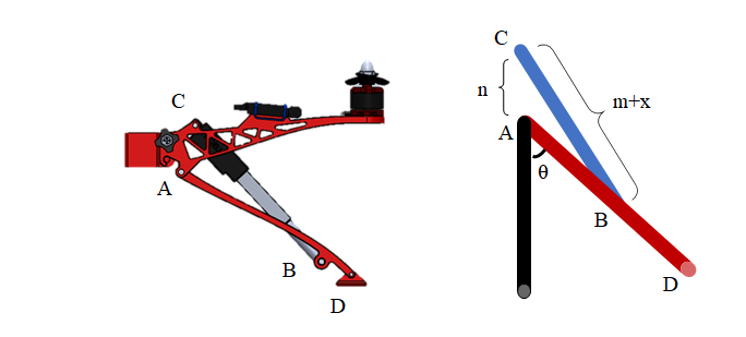
As seen from Figure 8, with the linear actuator BC elongation, the landing gear moves with A as the center of the circle, the linear actuator elongation length is set as \( x \) , and the angle between the landing gear and the vertical line is set as \( θ \) . We can get the relationship between \( x \) and \( θ \) .
\( x=\frac{-2m+\sqrt[]{4m+8n\sqrt[]{{m^{2}}-{n^{2}}}*cos{θ}}}{2} \) (1)
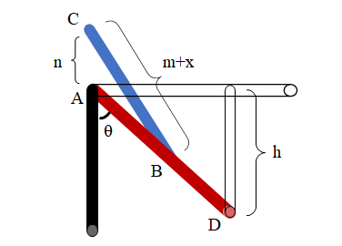
The relationship can be derived from \( θ \) , and then by the following equation, the height h of the landing gear foot from the UAV can be found, corresponding to the schematic diagram shown in Figure 9.
\( h=Lcos{θ} \) (2)
|
Figure 9. The landing gear changes height. |
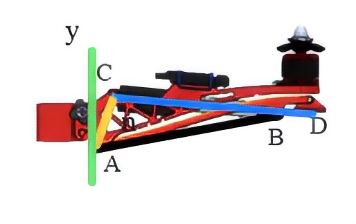
However, in the actual design, A and C are not necessarily in the same vertical line with each other, as is the case with the reference model used. For the reference model. \( L \) =140mm, \( m \) =126mm, and \( n \) =41mm, \( n \) has a numerical angle of \( 17° \) with respect to the y-axis. The corresponding schematic is shown in Figure 10.
|
Figure 10. Mathematical model of the reference model. |
This would increase the complexity of the equation considerably. In the reference model, we obtained a total of 400 sets of \( x \) vs. \( h \) data from \( x \) =0mm to \( x \) =110mm and substituted them into OriginPro 2022 for fitting and obtained the results in Figure 11.
|
Figure 11. Fitting results. |
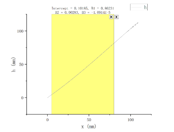
The final fitted mathematical model is shown below, which is only applicable to the model structure applied in this paper.
\( h=-1.0194*{10^{-5}}{x^{3}}+0.00283{x^{2}}+0.86231x+0.10185 \) (3)
5. Adaptive landing gear system algorithm design
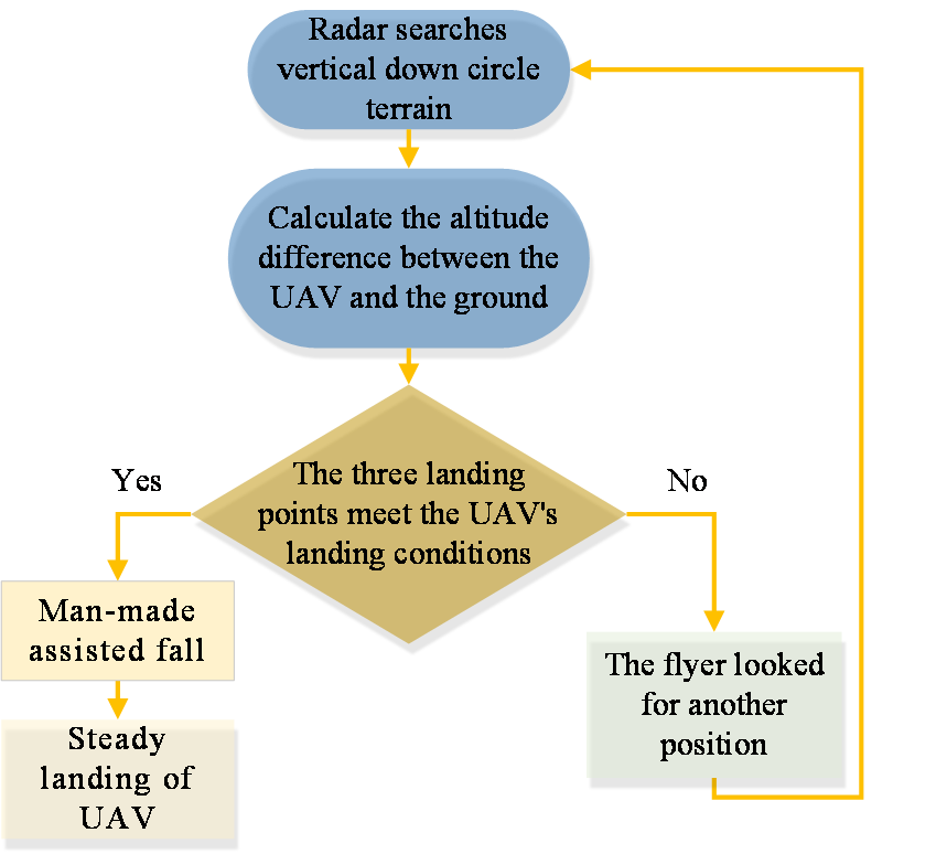
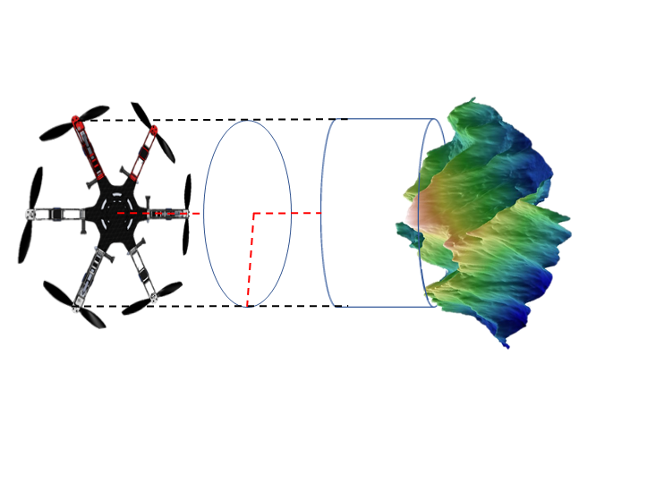
During the landing process, the UAV's radar will scan the ground with the center of the fuselage as the circle and the length of the landing gear as the radius to get the height difference of the UAV from the ground, and determine the UAV's landing point according to the ground height. Then the landing gear height will be adjusted by driving the linear actuator to match the height of the landing gear with the ground undulation, and finally achieve a smooth landing [18].
Let the leg length of the UAV be L cm and the angle of intersection between the UAV leg and the vertical downward plumb line be θ. Therefore, the vertical downward area of the circle with the radius of \( {L^{ \prime }} \) (the whole UAV leg length plus half of the fuselage) is scanned by the LIDAR, and we choose the column coordinate system to calculate the problem. \( r \) , \( φ \) , and \( z \) are the three coordinate variables. There is a \( z \) variable in the column coordinate system. \( r \) is the distance between the origin O and the projection M' of the point M on the plane xoy, and under this objective, the vector direction of \( r \) is the pointing of UAV leg1. This r \( ∈ \) [0, \( {L^{ \prime }} \) ]. \( φ \) is the angle turned from the positive z-axis to OM' in a counter clockwise direction from the x-axis, \( φ ∈ \) [0, 2π), \( z \) is the height of the cylinder, and the z-axis coincides with the mid-pipeline of the UAV.
Because the UAV has three legs and is symmetrical to each other, the legs are separated by 120 degrees, so the coordinates on each of the three legs are ( \( {r_{1}}, 0°,{z_{1}} \) ), ( \( {r_{2}}, 120°,{z_{2}} \) ), and ( \( {r_{3}}, 240°,{z_{3}} \) ) when obtaining the laser scan point. Where \( {r_{n}} \) is the distance of the center of the circle from the coordinate and \( {z_{n}} \) is the vertical height of the UAV from that coordinate. The coordinates are imported into an excel sheet by calculating them, importing and using C language to perform the operation. Which satisfies the equation conditions as follows.
\( {L_{m}}*cos{θ_{m}}={H_{m}} (m=1,2,3 they are the three legs of UAV) \) (4)
\( {L_{m}}*sin{θ_{m}}={X_{m}}(m=1,2,3 they are the three legs of UAV) \) (5)
In the above equation, \( {H_{m+1}}-{H_{m}}=∆{H_{m}} \) satisfies [0, L]. Here \( {X_{m}} \) satisfies [0, L], and this condition is satisfied by default when \( {H_{m}} \) satisfies the condition. When the three points satisfying Eqs. (4) and (5) are the points where the UAV can land stably, so the UAV performs a stable descent under the condition of artificial assistance.
The three points that satisfy the condition are 6cm, 9cm and 12cm, where the equation \( {z_{n+1}}-{z_{n}}=∆{z_{n}} \) , and the height difference \( ∆{H_{m}} \) of the three points are both 3cm, respectively. We determine \( θ \) by \( x \) , and determine whether the height difference is satisfied by \( θ \) . Under the condition that the height difference is satisfied, we find the elongation of the linear actuator through the equation of linear actuator elongation and angle \( θ \) , and complete the transformation of the whole structure. The overall algorithm flow structure diagram is shown in Figure 12 and its corresponding schematic diagram is shown in Figure 13.
|
|
Figure 12. Algorithm flowchart. | Figure 13. Landing process. |
After the UAV landing, due to the existence of a certain impact during the descent and the complex and variable ground conditions (such as soil blocks being crushed or small stones bouncing off), it is not guaranteed that the UAV's fuselage is completely horizontal after landing. At this time, the controller receives signals from the gyroscope, processes them and passes them to the motor controlling the linear actuator respectively, and makes appropriate fine-tuning of the fuselage angle to ensure that the UAV does not tip over. Because the electric linear actuator has reverse self-locking function, so it can ensure the position of UAV is fixed after landing to adjust whether it is powered on or not. When the UAV leaves the ground, all the linear actuators return to the shortest position, the landing gear retracts, and the control system automatically corrects the landing gear position and linear actuator length to zero.
6. UAV adaptive landing simulation
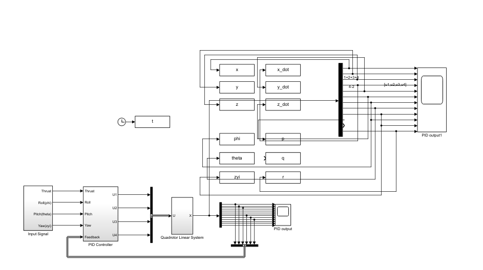
After completing the software part, under the hardware module we carried out PID landing simulation of the rotorcraft with SIMULINK. the UAV landed by identifying the landing point and we designed the simulation to maintain stability when the UAV fell to a certain height. Figure 14 shows the simulation model of the system.
|
Figure 14. Simulation model of the system. |
We adjusted the initial altitude position of the UAV to 1 meter, and initialize the roll angle, yaw angle, pitch angle. The UAV was set to land on a 0.4m stone. The Figure 15 shows the change in height, and angle adjustment during the UAV's landing.
|
Figure 15. Altitude and attitude response. |
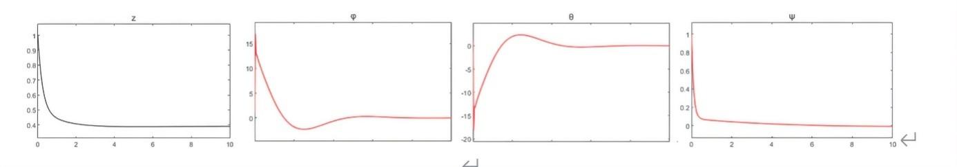
The simulation results illustrate that the UAV landed steadily from an altitude of 1 meters to 0.4 meters with sensitive angle adjustment, which indicate that the UAV has high stability, strong self-adaptability and good engineering application value.
7. Conclusion
In this paper, a landing gear and its corresponding landing algorithm are designed to adapt to complex ground conditions based on an existing DJI model. Firstly, a retractable landing gear and its two corresponding foots are designed to adapt to different terrains, then a mathematical model is developed based on the existing DJI model to analyze the structure of the retractable landing gear and to fit it. Next, an algorithm model is designed for the landing process of the UAV. Finally, we have simulated the UAV landing using MATLAB. The content of this paper ensures the feasibility of UAV landing in complex terrain and compatibility with many different complex terrains, which has good practical application value and reference significance.
Appendix
Table 1. Explanation of algorithm symbols.
Serial number | Symbol | Meaning |
1 | \( m \) | \( means the three legs(1,2,3) of UAV \) |
2 | \( n \) | \( means the Coordinates of different points \) |
3 | \( L \prime \) | Half of the UAV body length plus leg length |
4 | \( θ \) | The angle between the leg of UAV and the mid-pipeline |
5 | \( L \) | UAV's leg length |
6 | \( ∆H \) | Height difference of adjacent leg of UAV |
Algorithm 1: Coordinate traversal in cylindrical coordinate system |
Input: Coordinates in excel ( \( {r_{n}}, {φ_{n}}, {z_{n}} \) ). Output: Three suitable point coordinates ( \( {r_{1}}, {φ_{1}}, {z_{1}} \) ), ( \( {r_{2}}, {φ_{2}}, {z_{2}} \) ), ( \( {r_{3}}, {φ_{3}}, {z_{3}} \) ). |
1 Initializes the Angle of leg in column coordinates: \( {φ_{1}}=0° \) , \( {φ_{2}}=120° \) , \( {φ_{3}}=240° \) ; 2 While( \( {φ_{n}}==0° \) or \( 120° \) or \( 240° \) )do 3 for( ( \( {L_{m}}*sin{θ_{m}}={r_{n}} \) )and( \( {L_{m}}*cos{θ_{m}}={H_{m}} \) ) )do 4 if(Hm+1 \( - \) Hm \( ==z \) n+1 \( - \) zn) do 5 Pick the right coordinates ( \( {r_{n}}, {φ_{n}}, {z_{n}} \) ). 6 end if 7 m \( ← \) m+1; 8 n \( ← \) n+1; 9 end for 10 Return ( \( {r_{1}}, {φ_{1}}, {z_{1}} \) ), ( \( {r_{2}}, {φ_{2}}, {z_{2}} \) ), ( \( {r_{3}}, {φ_{3}}, {z_{3}} \) ) |
References
[1]. Mahadevan, P. (2010). The Military Utility of Drones. CSS Analyses in Security Policy, 78.
[2]. Ozdemir, U., Aktas, Y. O., Vuruskan, A., Dereli, Y., Tarhan, A. F., Demirbag, K., Erdem, A., Kalaycioglu, G. D., Ozkol, I., & Inalhan, G. (2014). Design of a Commercial Hybrid VTOL UAV System. Journal of Intelligent & Robotic Systems, 74, 371–393.
[3]. Çetinsoy, E., Sirimoğlu, E.F.E., Öner, K.T., Hancer, C., Ünel, M., Akşit, M.F., Kandemir, İ., and Gülez, K. (2011). Design and Construction of a Novel Quad Tilt-Wing UAV. Mechatronics, 19, 723–745.
[4]. Ollero, A. (2011). Modeling and Simulation of the HADA Reconfigurable UAV. Journal of Intelligent & Robotic Systems, 65(1573-0409), 115-122.
[5]. Jung, Y., & Shim, D. H. (2012). Development and Application of Controller for Transition Flight of Tail-Sitter UAV. Journal of Intelligent & Robotic Systems, 65, 137-152.
[6]. Low, J. E., Win, L. T. soe, Shaiful, D. S. bin, Tan, C. H., Soh, G. S., & Foong, S. (2017). Design and Dynamic Analysis of a Transformable HOvering Rotorcraft (THOR). IEEE, 6389-6396.
[7]. Mendoza, J. M., Cervantes, G. S., Ibanez, C. A., Mendez, M., Larios, M. R., Matabuena, P., & Avila, J. G. (2015). Air-Arm: A New Kind of Flying Manipulator. IEEE, 10, 278-287.
[8]. Boix, D. M., Goh, K., & Whinnie, james Mc. (2017). Modelling and Control of Helicopter Robotic Landing Gear for Uneven. IEEE, 60-65.
[9]. Hu, D., Li, yang , Xu, M., & Tang, Z. (2018). Research on UAV Adaptive Landing Gear Control System. Journal of Physics: Conference Series, 1061 012019, 1-6.
[10]. Ware, M. (2015, July 8). DJI F450/550 Landing Gear System V2. GRABCAD COMMUNITY.
[11]. Ciuonzo, D., Maio, A. D., & Orlando, D. (2015). A Unifying Framework for Adaptive Radar Detection in Homogeneous plus Structured Interference-Part II: Detectors Design. IEEE, 1507.05266.
[12]. Huang, M. (2019). Control Strategy of Launch Vehicle and Lander with Adaptive Landing Gear for Sloped Landing. Acta Astronautica, 207, 509–523.
[13]. Stolz, B., Gasser, J., Erne, D., Brodermann, T., Castiello, E., Englberger, G., Hutter, marco , Vandeventer, L., Hayoz, E., Muller, S., Mühlebach, L., Löw, T., Scheuer, D., Höpflinger, M., Bjelonic, M., Gunther, F., & Kolvenbach, H. (2018). An Adaptive Landing Gear for Extending the Operational Range of Helicopters. IEEE, 1757–1763.
[14]. Simplify mechanical. (2021, May 7). Basic Hydraulic System Circuit Diagram and Working Animation. YouTube.
[15]. Cary mart. (2022, July 24). Two Electric Micro Linear Actuators. YouTube.
[16]. Liu, J., Zhang, D., Wu, C., Tang, H., & Tian, C. (2021). A Multi-Finger Robot System for Adaptive Landing Gear and Aerial Manipulation. Robotics and Autonomous Systems, 146, 509–523.
[17]. Tang, H. (2021). A Novel Terrain Adaptive Landing Gear Robot. Journal of Physics: Conference Series, 1924.
[18]. Nie , H., Ni, X., Yin, Q., Wei, X., & Zhong, P. (2022). Research on Landing Stability of Four-Legged Adaptive Landing Gear for Multirotor UAVs. Aerospace, 9, 1–14.
Cite this article
An,N.;Liu,J.;Zhou,Z. (2023). Design of a landing gear system for UAV in complex ground environments. Applied and Computational Engineering,9,129-139.
Data availability
The datasets used and/or analyzed during the current study will be available from the authors upon reasonable request.
Disclaimer/Publisher's Note
The statements, opinions and data contained in all publications are solely those of the individual author(s) and contributor(s) and not of EWA Publishing and/or the editor(s). EWA Publishing and/or the editor(s) disclaim responsibility for any injury to people or property resulting from any ideas, methods, instructions or products referred to in the content.
About volume
Volume title: Proceedings of the 2023 International Conference on Mechatronics and Smart Systems
© 2024 by the author(s). Licensee EWA Publishing, Oxford, UK. This article is an open access article distributed under the terms and
conditions of the Creative Commons Attribution (CC BY) license. Authors who
publish this series agree to the following terms:
1. Authors retain copyright and grant the series right of first publication with the work simultaneously licensed under a Creative Commons
Attribution License that allows others to share the work with an acknowledgment of the work's authorship and initial publication in this
series.
2. Authors are able to enter into separate, additional contractual arrangements for the non-exclusive distribution of the series's published
version of the work (e.g., post it to an institutional repository or publish it in a book), with an acknowledgment of its initial
publication in this series.
3. Authors are permitted and encouraged to post their work online (e.g., in institutional repositories or on their website) prior to and
during the submission process, as it can lead to productive exchanges, as well as earlier and greater citation of published work (See
Open access policy for details).
References
[1]. Mahadevan, P. (2010). The Military Utility of Drones. CSS Analyses in Security Policy, 78.
[2]. Ozdemir, U., Aktas, Y. O., Vuruskan, A., Dereli, Y., Tarhan, A. F., Demirbag, K., Erdem, A., Kalaycioglu, G. D., Ozkol, I., & Inalhan, G. (2014). Design of a Commercial Hybrid VTOL UAV System. Journal of Intelligent & Robotic Systems, 74, 371–393.
[3]. Çetinsoy, E., Sirimoğlu, E.F.E., Öner, K.T., Hancer, C., Ünel, M., Akşit, M.F., Kandemir, İ., and Gülez, K. (2011). Design and Construction of a Novel Quad Tilt-Wing UAV. Mechatronics, 19, 723–745.
[4]. Ollero, A. (2011). Modeling and Simulation of the HADA Reconfigurable UAV. Journal of Intelligent & Robotic Systems, 65(1573-0409), 115-122.
[5]. Jung, Y., & Shim, D. H. (2012). Development and Application of Controller for Transition Flight of Tail-Sitter UAV. Journal of Intelligent & Robotic Systems, 65, 137-152.
[6]. Low, J. E., Win, L. T. soe, Shaiful, D. S. bin, Tan, C. H., Soh, G. S., & Foong, S. (2017). Design and Dynamic Analysis of a Transformable HOvering Rotorcraft (THOR). IEEE, 6389-6396.
[7]. Mendoza, J. M., Cervantes, G. S., Ibanez, C. A., Mendez, M., Larios, M. R., Matabuena, P., & Avila, J. G. (2015). Air-Arm: A New Kind of Flying Manipulator. IEEE, 10, 278-287.
[8]. Boix, D. M., Goh, K., & Whinnie, james Mc. (2017). Modelling and Control of Helicopter Robotic Landing Gear for Uneven. IEEE, 60-65.
[9]. Hu, D., Li, yang , Xu, M., & Tang, Z. (2018). Research on UAV Adaptive Landing Gear Control System. Journal of Physics: Conference Series, 1061 012019, 1-6.
[10]. Ware, M. (2015, July 8). DJI F450/550 Landing Gear System V2. GRABCAD COMMUNITY.
[11]. Ciuonzo, D., Maio, A. D., & Orlando, D. (2015). A Unifying Framework for Adaptive Radar Detection in Homogeneous plus Structured Interference-Part II: Detectors Design. IEEE, 1507.05266.
[12]. Huang, M. (2019). Control Strategy of Launch Vehicle and Lander with Adaptive Landing Gear for Sloped Landing. Acta Astronautica, 207, 509–523.
[13]. Stolz, B., Gasser, J., Erne, D., Brodermann, T., Castiello, E., Englberger, G., Hutter, marco , Vandeventer, L., Hayoz, E., Muller, S., Mühlebach, L., Löw, T., Scheuer, D., Höpflinger, M., Bjelonic, M., Gunther, F., & Kolvenbach, H. (2018). An Adaptive Landing Gear for Extending the Operational Range of Helicopters. IEEE, 1757–1763.
[14]. Simplify mechanical. (2021, May 7). Basic Hydraulic System Circuit Diagram and Working Animation. YouTube.
[15]. Cary mart. (2022, July 24). Two Electric Micro Linear Actuators. YouTube.
[16]. Liu, J., Zhang, D., Wu, C., Tang, H., & Tian, C. (2021). A Multi-Finger Robot System for Adaptive Landing Gear and Aerial Manipulation. Robotics and Autonomous Systems, 146, 509–523.
[17]. Tang, H. (2021). A Novel Terrain Adaptive Landing Gear Robot. Journal of Physics: Conference Series, 1924.
[18]. Nie , H., Ni, X., Yin, Q., Wei, X., & Zhong, P. (2022). Research on Landing Stability of Four-Legged Adaptive Landing Gear for Multirotor UAVs. Aerospace, 9, 1–14.