


1. Introduction
With the increasing maturity of computer technology and internet technology, drone technology has been applied to more and more fields. UAVs began to replace people for high repetitive tasks, such as sprinkling pesticides, forest patrol and sea patrol, etc. It also began to replace people for high risk tasks, for example, forest fire prevention, people can use UAVs high mobility of fire investigation, and carry fire bombs to put out fire by air. Thus, firefighters only need to put out the fire manually outside the disaster area, which greatly reduces unnecessary casualties [1, 2].
Fixed-wing UAVs are mostly used by officials, such as police or military daily inspections, rescue and relief. There are some large lethal UAVs, such as China's "Rainbow" series UAV and "Wing Loong" series UAV, and, of course, "Soar Dragon" UAV designed for reconnaissance. These UAVs have their unique wing layout, the most common is the combination of flat wing and V-type tail wing. In addition to the domestic "rainbow" and "wing dragon", there are also foreign "predators", "death" and "global eagle" are this wing configuration [3].
In response to the common problems of long preparation time and poor maneuverability of unmanned aerial vehicles, this paper studies the aerodynamic layout of unmanned aerial vehicles and proposes a new layout. Firstly, the aerodynamic layout of typical UAVs is introduced and compared and analyzed. Then a new type of compound wing UAV is designed by screening and analyzing the wing, flight analysis, main wing and UAV production process with Reynolds number. Subsequently, simulation experiments were conducted to analyze and optimize the aerodynamic layout performance of the designed UAVs. Finally, the entire content is summarized and analyzed.
2. Aerodynamic layout and comparison of UAV
2.1. Flying wing layout
The development of flying wing aircraft is similar to that of the early 20th century, and it marks its maturity stage when the B-2 stealth strategic bomber appeared in 1978. Now there are also many successful flying wing UAVs, such as the X-47B Neuron UAV of the United States and the Chinese Sword Stealth Unmanned Attack Aircraft. The aircraft with flying wing layout adopts wing-body fusion technology to improve aerodynamic efficiency, increase flight range, and have good radar stealth performance. Compared with the aircraft with conventional layout, the flying wing layout cancels the tail wing, and the whole body forms a large lift surface, just like a huge wing in flight, greatly improving the aerodynamic efficiency of the aircraft and increasing lift [4]. However, the flying wing aircraft also has the disadvantages of poor heading stability and poor pitching control.
2.2. Canard wing layout
The canard layout mainly makes use of the coupling of the vortex and the vortex of the front of the front of the main wing, so as to improve the aerodynamic performance of the main wing and improve the lift. In addition to improving the lift, the canard wing layout aircraft has better mobility than the conventional aircraft, and the existence of the canard wing makes the aircraft not easy to stall, which is more conducive to flight safety. However, the canard layout is deficient in design difficulties, complex structure and unfavorable stealth. The canard layout is more used in the design of fighter aircraft, such as China's J-20 and France's Rafale [5].
2.3. Other aerodynamic layout
In addition to the flying and canard layouts, there are conventional layouts, swept-back wings, prism wings, and more. Conventional layout refers to a layout that places the vertical tail and tail on the tail of the main wing. Its biggest advantage is a long development history, perfect theoretical research, mature and stable technology, high reliability, and the performance is relatively balanced. But because of its more balanced performance, it cannot do the most in a particular area.
The swept wing is currently the most widely used wing layout, especially for some wings that require swept wings of high-speed fighter jets. The most intuitive advantage is the ability to decompose the airflow ahead, causing it to decompose along and perpendicular to the wing, in order to improve the subsonic flight of the aircraft. While not producing the maximum number of impacts, it can also increase the lateral static stability and Directional stability, and increase the resistance coefficient. [6], [7]. However, the swept wing has the disadvantage of insufficient lift at the front edge of the wing, which makes its take-off and landing performance is poor, and the larger the swept angle, the more obvious this disadvantage is. So there is an improved version called the variable swept-back wing, in which the aircraft can use smaller sweep angles during take-off and landing, and gradually open larger sweep angles when the flight stabilizes, such as the B-1B heavy supersonic strategic bomber.
3. Design and combination of the canard and the flying wing
The method proposed in this article addresses the current issues of long preparation time and poor maneuverability by neutralizing the characteristics of canards and flying wings, thereby improving flight speed, load capacity, and safety performance.
3.1. The determination of the wing type
The Reynolds number \( {R_{e}} \) is a dimensionless number used to characterize the fluid flow case that can be calculated using this equation:
\( {R_{e}}=\frac{αvL}{β} \) (1)
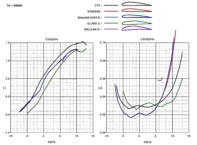
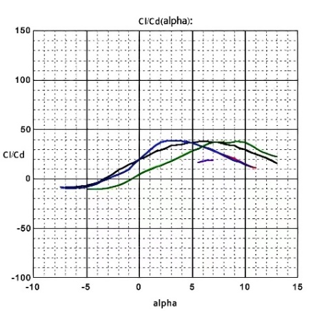
where \( α \) , \( β \) are the fluid density and dynamical viscosity coefficient, and \( v \) , \( L \) are the characteristic velocity and characteristic length of the flow field [4]. It can also be calculated using the program in Profili. In Profili, only need to determine the flight altitude, speed and geometric string length of the wing can be determined to calculate the size of the Reynolds number at a certain height [8]. The specific flight airspace of the canard configuration UAV is in the range of 100 m to 1000 m, and the maximum flight speed of the UAV is 25 m/s. The cruise speed is determined as 15 m/s, the wing string length of the aircraft is determined as 237.5 mm, and the wing area is determined to be 1800 cm2. So the Reynolds number is in the range of 210,000 to 230,000 by Profili calculation. Preliminary screening of airfoil was conducted using Profili software, and various C72, CLARKX, NACA 6412, BE9403B, Benedek 9403 B were selected. The data of these airfoil were analyzed based on Reynolds number. The results are shown in figure 1 and figure 2.
|
|
Figure 1. Lift coefficient curve (left), resistance coefficient curve (right). | Figure 2. Elevation resistance ratio curve. |
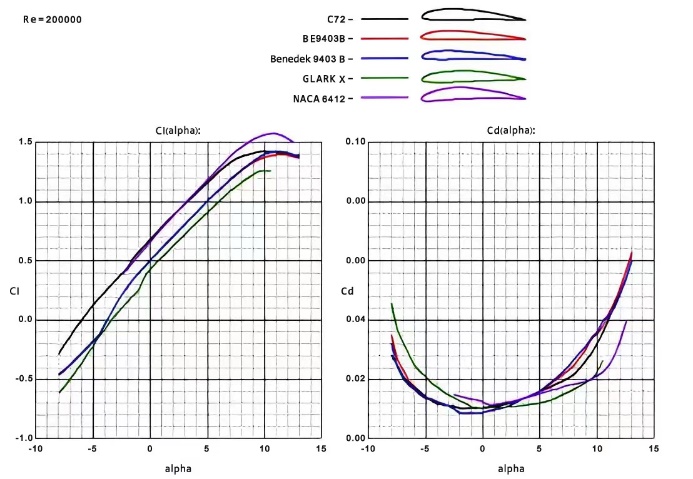
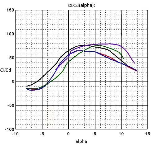
As can be seen in figures 1 and figures 2, at a smaller angle of attack, The C72 airfoil has superior lift-resistance ratio characteristics, while the NACA 6412 airfoil performs better at a large angle of attack. To prevent the stall of the first tip of the canard and main wing, the NACA6412 airfoil can be used as the canard, while the C72 wing serves as the wing of the main wing. At the same time, the two air types were improved using XFLR5 software. Cut the main wing into two internal and outer parts. Appropriately increase the maximum curvature of the outer section airfoil, and move the maximum bending position back appropriately, so that it obtains a more moderate stalling characteristics, which ensure a greater controllable range [9-11].
3.2. Design of the main wing
The swept angle is the angle from the average aerodynamic chord length of the wing from the wing root to the wing tip, which is the angle between the wing and the fuselage. The existence of the swept angle can make the flow decomposition along the wing direction and perpendicular to the wing direction, to improve the plane's subsonic flight but not produce the maximum number of shock waves. It also can increase the lateral static stability and direction stability, and make the drag coefficient growth rate, to enhance the stability of the UAV is of great help. But the swept wing in the angle of attack is larger, due to the emergence of wing tip effect and wing root effect, can make the wing on the upper surface wing root pressure is greater than the tip of the tip. The existence of the pressure difference causes airflow flow along the wingspan direction, so that the surface layer in the tip thicker, more likely to produce air separation, causing the wing tip stall.
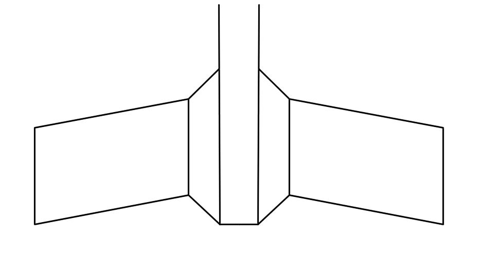
The UAVs with flying wing layout are generally designed in the form of leading double-back, and the same is true of this design, as shown in figure 3. In order to improve the load capacity of the UAV and increase the body space, and reduce the flight resistance and body size, the middle part of the wing adopts octagonal shape design, and make it slightly raised, forming a fat structure in the middle and thin structure on both sides [11]. In this way, both the inner wing and the outer wing can adopt a smaller sweep angle, which is conducive to increase the wing area, reduce the wing surface load, and adapt to low speed flight. This design sets the sweep angle of the front edge of the inner wing as 40 degrees, while the sweep angle of the leading edge of the outer wing is 10 degrees.
|
Figure 3. Wing geometry design. |
3.3. Determination of the relative position of the main wing to the canard wing
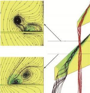
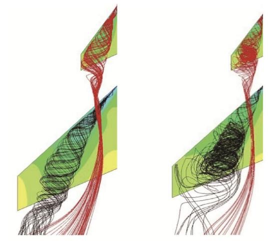
The canard is a wing layout mounted in front of the main wing. The deflection changes the airflow to affect the flow field of the main wing, as shown in figure 4. The airflow will form vortex when passing through the wing. On the inside of the main wing, the canard wing vortex is located on the outside of the front edge of the main wing, it plays a downwash role on the leading edge vortex of the main wing, reduces the effective angle of attack in this area, inhibits the development of the leading edge vortex of the main wing, and causes partial lift loss. At the outer side of the main wing, the canard vortex is located at the inner side of the leading edge vortex of the main wing, which plays the role of up-washing the leading edge vortex of the main wing. While pushing the leading-edge vortex of the main wing outward, on the one hand, it makes the leading-edge vortex of the main wing tend to be stable, and on the other hand, it makes the area of the leading-edge vortex of the main wing narrow, which reduces its role in raising the wing lift [12].
When the angle of attack is gradually increased, the influence of the main wing leading edge vortex will gradually tend to medial washing. In the stability of the front of the main wing vortex and main wing leading edge vortex further coupling enhancement, thus increase the lift coefficient of the wing. Until the maximum favorable angle of attack, and then if continue to increase the angle of attack, will lead to the coupling canard wing vortex and wing front edge vortex began to break, divergence, the wing will appear obvious stall, as shown in figure 5.
Therefore, it can be found that when there is a certain upper reverse angle in the canard wing, the body vortex generated by the airflow through the canard wing will be closer to the inside of the main wing, thus enhancing the upper washing effect of the canard wing vortex on the front edge of the main wing, and reducing the adverse effects of the canard wing vortex on the main wing.
|
|
Figure 4. Interaction of canard vortex and main wing vortex. | Figure 5. Eddy current at maximum favorable angle of attack (left) and stall (right). |
3.4. Performance analysis and cabibration of canard-flying wing UAV
3.5. Basic performance analysis of canard-flying wing UAV
Canard configuration UAV is to solve the problems of long preparation time and poor mobility, which neutralize the advantages of canard and flying wing and improve the flight speed, load capacity and safety performance.
In terms of flight speed, the traditional fixed-wing UAV can not reach 4 m/s ultra-low speed flight, but the parameters of the Profili software can obtain the characteristic curve when the flight speed is 4 m/s, as shown in figure 6 and figure 7. Thus, the canard flying wing aerodynamic layout UAV is fully capable of 4 m/s low speed flight, and a stable large angle of attack flight. If this UAV is used in the field of investigation, the attitude of the large angle of attack can have a broad view of the airborne camera, enabling it to focus on the detection of the target area.
|
|
Figure 6. Low-speed rise resistance coefficient character-istic curve. | Figure 7. Low-speed rise-resistance ratio curve. |
In terms of flexibility, Canard layout UAVs has high mobility, its minimum turning radius is 1.5 m, which make it able to adapt to the complex airspace or flying in the city. In terms of load, the canard aerial layout maximum take-off weight of 5 kg, the air weight of 1 kg, and the main wing has a larger space, this means that the canard aerial layout has enough load and space for carrying detection equipment and large capacity battery, make it can for a long time and effectively detect the target area.
3.6. Final design results of the canard-flying wing UAV
The canard configuration has a final wingspan of 1050 mm, a captain of 1005 mm and a wing area of 272913 mm2. Its maximum take-off weight of 5 kg, the minimum flight speed of 4 m/s, cruise speed of 15 m/s, the minimum turning radius of 1.5 m, takeoff distance about 5 m, landing taxi distance about 8m, Because of the body is small and stable large angle of attack flight, it also can use the hand take off and hand landing way to achieve the purpose of rapid landing.
According to the aircraft, power system selection Lang Yu X2212 KV1250 motor and good surplus sky walker 40 an electric collocation APC8060 propeller. The power system can be in the use of 4S battery and on the premise of current for 22.2 A provide 1000 grams of pull. Canard-flying wing aerial layout is using double generator, so under the action of two sets of power system, can get 2000 grams of pull.
4. Conclusions
Science is constantly improving, technology is constantly developing, and the UAV industry is in a stage of vigorous development. Aiming at the problems of long preparation time and poor maneuverability of canard and flying wing. In this paper, based on the wing layout of commonly used UAVs, the problems of long preparation time and poor maneuverability are solved from the aerodynamic layout. Then the characteristics of canard and flying wing can be realized through the method in this paper, and the high maneuverability and lift of canard can be brought into full play. Then the performance of UAV is verified by simulation experiment analysis and the final experimental results are analyzed. Finally, the simulation results show that the composite wing UAV designed in this paper can achieve good flight performance in complex airspace.
References
[1]. Liu Hu. Overall aircraft design [M]. Beijing: Beijing Aerospace University Press, 2019. [American] by Lehman, DP. Modern aircraft design [M].
[2]. Zhong Dingkui et al. Beijing: National Defense Industry Press, 1992.
[3]. Wu Zi-cow. Aerodynamics [M]. Beijing: Tsinghua University Press, 2007.
[4]. Serve the people peacefully. Analysis and calculation of aircraft [M]. Xi'an: Northwestern Polytechnical University Press, 2012.
[5]. Xing Lin Linlin. flight theory [M]. Beijing: Beijing Aerospace University Press, 2018.
[6]. Fang Baorui. Pneumatic layout design of the aircraft [M]. Beijing: Aviation Industry Press, 1997.
[7]. Min Shan Mountain. Pneumatic layout design and analysis of a certain type of tailless flying wing UAV [D]. Wuhan: Huazhong University of Science and Technology, 2015.
[8]. Guo Kezhi. The conceptual design and aerodynamic optimization of the high-altitude and long-endurance UAV series [D]. Nanjing: Nanjing University of Aeronautics and Astronautics, 2008.
[9]. Qin Bo, Wang Lei. Review of UAV development [J]. Flying missile, 2002.
[10]. Wu Xiaochun. UAVs first came out [J]. Aviation Knowledge, 2001.
[11]. Zhang Dong, Chen Yong, Hu Mengquan, et al. Effect of edge canard on aerodynamic characteristics of swept and swept wings. Journal of Beijing University of Aeronautics and Astronautics, 2019,45 (10): 2058-2068.
[12]. Feng Cong,Chen Shu-sheng,Yuan Wu,Li Zheng,Gao Zheng-hong. A wide-speed-range aerodynamic configuration by adopting wave-riding-strake wing [J]. Acta Astronautica, 2023, 202.
Cite this article
Chen,Y.;Gao,X.;Wu,T. (2023). A novel aerodynamic layout design of composite wing unmanned aerial vehicle based on canard configuration. Applied and Computational Engineering,9,188-193.
Data availability
The datasets used and/or analyzed during the current study will be available from the authors upon reasonable request.
Disclaimer/Publisher's Note
The statements, opinions and data contained in all publications are solely those of the individual author(s) and contributor(s) and not of EWA Publishing and/or the editor(s). EWA Publishing and/or the editor(s) disclaim responsibility for any injury to people or property resulting from any ideas, methods, instructions or products referred to in the content.
About volume
Volume title: Proceedings of the 2023 International Conference on Mechatronics and Smart Systems
© 2024 by the author(s). Licensee EWA Publishing, Oxford, UK. This article is an open access article distributed under the terms and
conditions of the Creative Commons Attribution (CC BY) license. Authors who
publish this series agree to the following terms:
1. Authors retain copyright and grant the series right of first publication with the work simultaneously licensed under a Creative Commons
Attribution License that allows others to share the work with an acknowledgment of the work's authorship and initial publication in this
series.
2. Authors are able to enter into separate, additional contractual arrangements for the non-exclusive distribution of the series's published
version of the work (e.g., post it to an institutional repository or publish it in a book), with an acknowledgment of its initial
publication in this series.
3. Authors are permitted and encouraged to post their work online (e.g., in institutional repositories or on their website) prior to and
during the submission process, as it can lead to productive exchanges, as well as earlier and greater citation of published work (See
Open access policy for details).
References
[1]. Liu Hu. Overall aircraft design [M]. Beijing: Beijing Aerospace University Press, 2019. [American] by Lehman, DP. Modern aircraft design [M].
[2]. Zhong Dingkui et al. Beijing: National Defense Industry Press, 1992.
[3]. Wu Zi-cow. Aerodynamics [M]. Beijing: Tsinghua University Press, 2007.
[4]. Serve the people peacefully. Analysis and calculation of aircraft [M]. Xi'an: Northwestern Polytechnical University Press, 2012.
[5]. Xing Lin Linlin. flight theory [M]. Beijing: Beijing Aerospace University Press, 2018.
[6]. Fang Baorui. Pneumatic layout design of the aircraft [M]. Beijing: Aviation Industry Press, 1997.
[7]. Min Shan Mountain. Pneumatic layout design and analysis of a certain type of tailless flying wing UAV [D]. Wuhan: Huazhong University of Science and Technology, 2015.
[8]. Guo Kezhi. The conceptual design and aerodynamic optimization of the high-altitude and long-endurance UAV series [D]. Nanjing: Nanjing University of Aeronautics and Astronautics, 2008.
[9]. Qin Bo, Wang Lei. Review of UAV development [J]. Flying missile, 2002.
[10]. Wu Xiaochun. UAVs first came out [J]. Aviation Knowledge, 2001.
[11]. Zhang Dong, Chen Yong, Hu Mengquan, et al. Effect of edge canard on aerodynamic characteristics of swept and swept wings. Journal of Beijing University of Aeronautics and Astronautics, 2019,45 (10): 2058-2068.
[12]. Feng Cong,Chen Shu-sheng,Yuan Wu,Li Zheng,Gao Zheng-hong. A wide-speed-range aerodynamic configuration by adopting wave-riding-strake wing [J]. Acta Astronautica, 2023, 202.