


1. Introduction
A gas turbine is an internal combustion engine that operates with rotation motion rather than reciprocating motion, which, alternatively, can be illustrated as a thermodynamic device that uses air and gas as the working medium. It is essentially composed of three major components, including compressors, combustors, and power turbines. After decades of development, gas turbines have been widely used in different fields, especially in the aviation industry. In this case, jet engines are the most often used engines, a type of gas turbine optimized to produce thrust and mechanical output from the exhaust gases. Due to gas turbines’ unique power-to-weight ratio, an engine with relatively low mass can produce significant useful work, making it perfectly fitted for aircraft propulsion and applied to different aircraft devices such as military planes, airplanes, rockets, and helicopters. Recent years have witnessed the severe impact of climate change, leading to an increased awareness of limiting the number of fossil fuels used in industry as combustion will directly contribute to global warming.
Nevertheless, it is inevitable to stop relying on the usage of gas turbines in terms of their availability. Therefore, engineers and scientists shift their focus onto finding better substitute fuels and materials and developing the system to maximize the amount of work generated with the least amount of combustion. In other words, means increasing thermal efficiency is the primary interest of development in the future.
2. The thermodynamic principle of gas turbine
2.1. Inner structure and working mechanism of gas turbine
This section covers the working process and the main components separately as modules, including the compressor, combustor, and power turbine as shown in Figure 1. This gives a general idea about the physical working mechanism of each of the main components within the gas turbine.
|
Figure 1. Exploded view of an animated gas turbine [1]. |
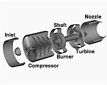
2.1.1. Compressor. Compressor is a device used to increase the pressure of a gas by reducing its volume. It is classified into two types, positive displacement compressor and dynamic compressor. The dynamic compressor includes axial flow and centrifugal compressor, most commonly used in gas turbine construction. The gas turbine pulls air into the engine, pressurizes it, and delivers it to the combustion chamber at high speeds. This process allows for the efficient operation of the engine. The speed at which the air is delivered can exceed several hundred miles per hour, ensuring that the combustion process is successful and powerful.
2.1.2. Combustor. The combustor, also known as a combustion chamber or burner, is made up of a ring of fuel injectors that supply a continuous fuel flow into the combustion chambers. The fuel mixes with the air and is burned at temperatures about 1800~2000 ℃ [2]. This high-temperature, high-pressure process generates a gas stream that enters the turbine section. The turbine is a complex system of rotating and stationary blades that combine to convert the gas stream's energy into mechanical output.
2.1.3. Turbine. The turbine consists of a complex arrangement of aerofoil-section blades that alternate between stationary and rotating. As the hot combustion gas expands through the turbine, it causes the rotating blades to spin. These rotating blades perform two functions where they drive the compressor to draw in more pressurized air into the combustion section and turn a generator that produces mechanical work.
2.1.4. Overall working mechanism. The air enters the axial compressor and is compressed to a specific pressure before being sent to the combustion chamber. At the same time, the fuel pump injects fuel into the combustion chamber, where it mixes with the compressed air, producing gas with temperatures reaching up to 1800~2300 K. Before entering the gas turbine, secondary cooling air, which makes up about 60%~80% of the total air volume, mixes with the high-temperature gas to lower the mixture's temperature to an appropriate level. In the gas turbine, the gas mixture expands in the nozzle, partially transforming heat energy into kinetic energy, forming a high-speed airflow. The airflow then enters the channel comprising dynamic blades fixed on the rotor, forming a thrust to push the blades and make the rotor rotate, outputting mechanical work.
2.2. Cycle analysis
In this section, some analysis of the cycle taking place in the gas turbine will be included to reinforce the thermodynamic fundamentals from both ideal and realistic aspects.
2.2.1. Ideal cycles. The functioning of a gas turbine is based on a process called the Brayton cycle, which can serve as a model for all similar units. In the case of a jet engine, the cycle operates in an open manner, meaning that the compressor takes in new gas while the combustion products are released from the turbine into the environment and not recirculated.
|
|
Figure 2. P-v diagram of air standard ideal Brayton cycle [3]. | Figure 3. T-s diagram of air standard ideal Brayton cycle [3]. |
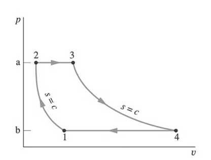
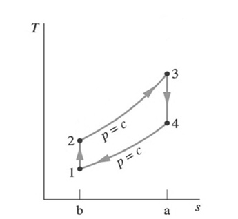
According to P-v and T-s graphs shown in Figures 2 and 3, the air is firstly compressed from 1 to 2 in a compressor, and heat is then added during the process 2 to 3, which takes in the combustion chamber. Process 3 to 4 represents the expansion of gas in the turbine. Line 34 is longer than line 21 on the T-s diagram. The turbine extracts more power than that needed to drive the compressor. Compression (1-2) and expansion (3-4) are isentropic processes in this ideal Brayton cycle. This means they simultaneously require both adiabatic and reversible processes, where the heat exchange is zero. Besides, heat addition (2-3) and heat rejection (4-1) are isobaric processes where the pressure is constant.
2.2.2. Realistic cycles. However, there is a difference between the ideal and actual performance of the gas turbine shown in the diagram due to the deviations from the ideal Brayton cycle. For instance, the ideal cycle ignores the effect of shock, friction, and aerodynamic losses. Since the performance of the cycle is affected by many variables, the actual cycle has a different P-v diagram with lower efficiency compared with the ideal one.
|
Figure 4. T-s diagram of actual air-standard gas turbine [3]. |
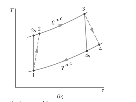
Due to the aforementioned factors, the entropy experienced by the working fluid will significantly increase across these components, leading to the right shift from 2 to 2s and 4 to 4s in the T-s graph illustrated in Figure 4. This causes the work generated by the turbine decreases and work input into the compressor increases, which causes lower net work done and lower efficiency, which can be calculated by the formula below.
\( {η_{t}}=\frac{({\dot{W}_{t}}/\dot{m})}{{({\dot{W}_{t}}/\dot{m})_{s}}}=\frac{{h_{3}}-{h_{4}}}{{h_{3}}-{h_{4s}}} \) (1)
\( {η_{c}}=\frac{{({\dot{W}_{c}}/\dot{m})_{s}}}{({\dot{W}_{c}}/\dot{m})}=\frac{{h_{2s}}-{h_{1}}}{{h_{2}}-{h_{1}}} \) (2)
3. Classification and current applications of gas turbines in the aviation industry
3.1. The turbojet
Turbojet engines are the oldest and simplest type of gas turbine engines. They work by compressing air and mixing it with fuel, igniting it to produce high-velocity exhaust gases that generate thrust. They are relatively simple in design, consisting of a compressor, combustion chamber, and turbine, but have high fuel consumption and noise levels. They are suitable for high-speed military aircraft but are less suitable for commercial aviation due to their limitations in fuel efficiency and noise pollution.
The General Electric J85-GE-5 is a simple and reliable engine designed for military aircraft. It has a high thrust-to-weight ratio [4], making it suitable for high-speed aircraft like the Northrop T-38 Talon. However, this engine has several disadvantages, including high fuel consumption and noise levels, which makes it less suitable for commercial aviation. The limited range of the engine is also a drawback due to its high fuel consumption. While it is a powerful engine, its efficiency is limited compared to more modern engines.
3.2. The turbofan
Turbofan engines work by compressing air with a fan, mixed with fuel and burned in a combustion chamber to produce exhaust gases that generate thrust. Compared to turbojet engines, turbofan engines have a larger fan that provides additional thrust by bypassing some of the air around the combustion chamber. This feature improves fuel efficiency and reduces noise levels, making turbofan engines the most widely used type of engine in commercial aviation. Turbofan engines are more complex in design compared to turbojet engines, consisting of a fan, compressor, combustion chamber, turbine, and bypass duct. They are highly efficient and reliable and can achieve high speeds while maintaining fuel efficiency.
The CFM56-5B is a highly efficient and reliable engine widely used in commercial aviation. Its large fan provides additional thrust by bypassing some of the air around the combustion chamber, improving fuel efficiency and reducing noise levels. The engine is more complex in design compared to turbojet engines, consisting of a fan, compressor, combustion chamber, turbine, and bypass duct [5]. It can achieve high speeds while maintaining fuel efficiency, making it an ideal choice for commercial aircraft like the Airbus A320. However, one of the disadvantages of the CFM56-5B is that it is relatively heavy compared to other engines, which can reduce the aircraft's payload capacity.
3.3. The turboshaft
Turboshaft engines use a turbine to drive a shaft, which is then used to power a helicopter rotor or other equipment. They are similar in design to turbofan engines but have a lower pressure ratio and a different turbine configuration. They are less efficient than other engine types but are highly reliable and have a high power-to-weight ratio. They are suitable for helicopter operations and other specialized applications.
The General Electric T700-GE-701C is a turboshaft engine commonly used in helicopters like the Sikorsky UH-60 Black Hawk. It has a simple, reliable design, long service life, and low maintenance requirements. It is also known for its high-power output, making it ideal for use in heavy helicopters [6]. However, one of the disadvantages of the engine is that it is relatively heavy, which can reduce the overall payload capacity of the aircraft. It also has limited speed and range compared to other types of aircraft engines.
3.4. The turboprop
Turboprop engines use a turbine to drive a propeller, which generates thrust by accelerating air backward. They are highly efficient and reliable but have a limited speed range compared to other engine types. They are suitable for regional and commuter aircraft operations and are capable of operating from short runways. They are quieter and produce less vibration than piston engines, which makes them ideal for accessing remote areas.
The Pratt & Whitney Canada PT6A-42 is a highly efficient and reliable turboprop engine commonly used in regional aircraft like the Pilatus PC-12. It is known for its low fuel consumption, making it ideal for short- to medium-range flights [7]. The engine is also relatively light in weight and has a high power-to-weight ratio, making it suitable for use in smaller aircraft. However, one of the disadvantages of the engine is that it has limited speed and altitude capabilities compared to other types of engines, which can limit its use in certain types of aircraft.
4. Future development and expectations
4.1. Methods to improve thermal efficiency
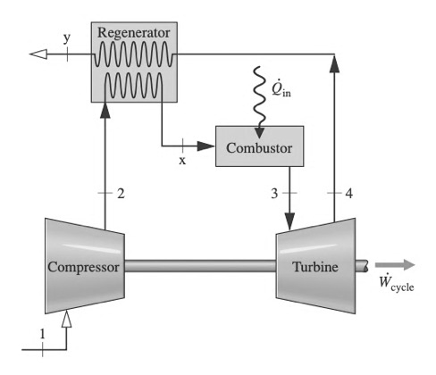
4.1.1. Regeneration. When it comes to open-loop gas turbine systems, the exhaust gases leaving the turbine always have a higher temperature than the inlet gases and the surrounding environment. This means that heat is constantly being rejected from the system to the environment. The more significant the temperature difference, the less heat is utilized in useful work, resulting in lower efficiency. To this end, a regeneration system is often added to recover rejected heat by heating gases before the combustion stage as shown in Figure 5. By placing the exhaust gas close enough to the inlet gas in a regenerator, heat will naturally transfer to the latter. As a result, Tx will be greater than T2, meaning less fuel is required during the combustion stage for gas expansion. Consequently, lower fuel demand leads to lower heat input and increased thermal efficiency. Calculations have demonstrated that implementing a regeneration system can result in an overall efficiency increase of more than 10% [8].
|
Figure 5. Regenerative gas turbine [3]. |
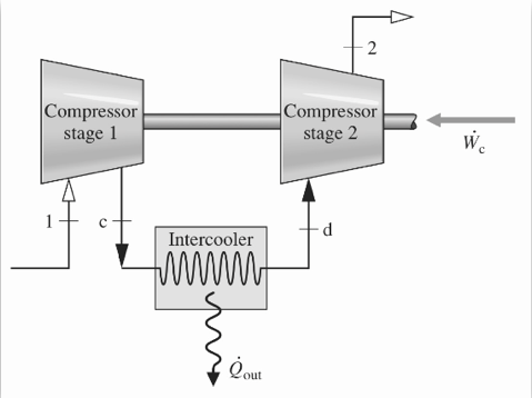
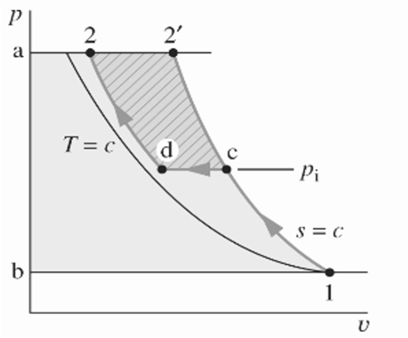
4.1.2. Inter-cooling. The inter-cooling process involves using a second compressor in a multi-stage compression process where the gas is cooled before entering the second compressor as demonstrated in Figure 6. Cooling the gas makes it denser, resulting in lower demand for compressor work and increased work output from the turbine [9]. The inter-cooling compression process requires less work than the normal compression process, as shown by the relatively smaller area under the inter-cooling path on the P-v diagram in Figure 7. However, similar to the reheating process, the intercooling process may reduce efficiency due to the extra heat rejected by the environment at the intercooler. Hence, the inter-cooling process is often combined with a regenerator to improve efficiency.
|
|
Figure 6. Two-stage compression with intercooling [3]. | Figure 7. P-v diagram of two-stage compression with intercooling [3]. |
4.1.3. Reheating. Another approach to increase work output is using a reheat process, where an additional turbine is added to the system as shown in Figure 9. In this method, exhaust gas from the first turbine is reheated to power the second turbine, producing more work. However, while the reheating process does increase work output, it does not necessarily improve efficiency [10]. This is because additional heat input occurs at the reheat combustor, as seen in Figure 8, where T4 is higher than T4'. As a result, the temperature difference between state 4 and state 1 increases, reducing thermal efficiency.
|
|
Figure 8. T-S diagram of the gas turbine with reheat [3]. | Figure 9. Gas turbine with reheat [3]. |
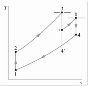
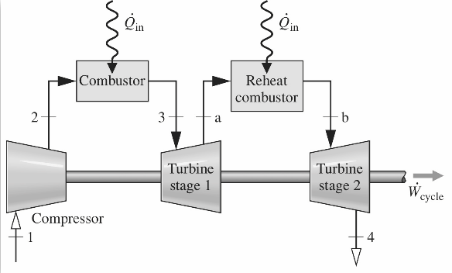
Despite the potential decrease in efficiency, the high exhaust temperature in a reheat process offers an opportunity to implement a regenerator, as the large temperature difference enables efficient heat transfer from the exhaust gas to the inlet gas. Therefore, a regenerator is often combined with reheating to increase efficiency further. In Figure 8, it can be observed that the expansion stage is divided into two parts, where instead of expanding directly from state 3 to 4', it first expands halfway to state a, then heats up to state b, and finally expands to state 4. With a regenerator in place, the higher temperature of the exhaust gas can be used to preheat the inlet gas, resulting in less fuel consumption during combustion and, ultimately, higher efficiency.
4.2. Future development of gas turbine
Currently, ongoing research and development are focused on improving their efficiency and reducing their environmental impact. New technologies like additive manufacturing and digitalization have enabled manufacturers to produce more advanced and efficient gas turbines. Additionally, the aviation industry is exploring new technologies, such as hybrid electric propulsion, that could further reduce emissions and fuel consumption.
5. Conclusions
Gas turbines have revolutionized the aviation industry by providing reliable and efficient power to aircraft. The high power-to-weight ratio and ability to operate at high altitudes and extreme weather conditions make gas turbines ideal for aircraft engines. They offer a significant advantage over traditional piston engines as they can convert more of the energy in their fuel into useful work. This increased efficiency reduces fuel consumption and emissions, making them more environmentally friendly. Additionally, gas turbines can operate at higher speeds and altitudes, making air travel faster, safer, and more efficient.
However, gas turbines have several limitations. The most significant concern is their contribution to air pollution and global warming. Although modern gas turbine engines emit fewer pollutants than their predecessors, they still release significant amounts of greenhouse gases contributing to climate change. As a result, the aviation industry has been actively seeking ways to reduce its carbon footprints, such as exploring alternative fuels like biofuels and electric propulsion. Another limitation is their cost, both in terms of manufacturing and maintenance. Gas turbines are expensive to manufacture, and their complex design requires specialized skills and knowledge to operate and repair. This complexity makes maintenance more challenging, increasing the risk of failures and downtime.
In conclusion, gas turbines are a vital technology for the aviation industry, providing reliable and efficient power to aircraft. Despite their limitations, they have revolutionized air travel, enabling faster, safer, and more efficient flights. While the industry continues to face challenges regarding its cost and environmental impact, ongoing research and development are focused on addressing these issues. Gas turbines will remain a critical component in aviation, and as the industry moves towards more sustainable practices, they will continue to evolve to meet the needs of the modern world.
References
[1]. Glenn Research Center 2021 Animated gas turbine parts https://www.grc.nasa.gov/www/k-12/airplane/turbparts.html
[2]. Heinz P and Claire S 1998 Butterworth-Heinemann, Cop Process plant machinery, 2nd edition 49
[3]. Moran M, Shapiro H, Boettner D and Bailey M 2018 John Wiley & Sons, Inc Fundamentals of engineering thermodynamics 529
[4]. Balli O 2020 Engineering Failure Analysis 115 104700
[5]. Arshad A, Andrew N and Blumbergs I 2020 In 2020 11th International Conference on Mechanical and Aerospace Engineering (ICMAE), IEEE 162
[6]. Corporan E, DeWitt M, Klingshirn C, Striebich R and Cheng M 2010 Journal of Propulsion and Power 26 318
[7]. Rabeta B, Tajuddin A, Abghi M, Ulhaq F, Sugiharto A, Penerbangan P, Kedirgantaraan T, Dirgantara U, Suryadarmakomplek B and Perdanakusuma H 2021 Jurnal Teknologi Kedirgantaraan 6 44
[8]. Göktun S and Yavuz H 1999 Energy Conversion and Management 40 1265
[9]. Canière H, Willockx A, Dick E and De P 2006 Applied Thermal Engineering 26 1786
[10]. Khaliq A and Kaushik S 2004 Applied Thermal Engineering 24 1794
Cite this article
Li,T. (2023). The performances and applications of gas turbines in the aviation industry. Applied and Computational Engineering,11,104-110.
Data availability
The datasets used and/or analyzed during the current study will be available from the authors upon reasonable request.
Disclaimer/Publisher's Note
The statements, opinions and data contained in all publications are solely those of the individual author(s) and contributor(s) and not of EWA Publishing and/or the editor(s). EWA Publishing and/or the editor(s) disclaim responsibility for any injury to people or property resulting from any ideas, methods, instructions or products referred to in the content.
About volume
Volume title: Proceedings of the 2023 International Conference on Mechatronics and Smart Systems
© 2024 by the author(s). Licensee EWA Publishing, Oxford, UK. This article is an open access article distributed under the terms and
conditions of the Creative Commons Attribution (CC BY) license. Authors who
publish this series agree to the following terms:
1. Authors retain copyright and grant the series right of first publication with the work simultaneously licensed under a Creative Commons
Attribution License that allows others to share the work with an acknowledgment of the work's authorship and initial publication in this
series.
2. Authors are able to enter into separate, additional contractual arrangements for the non-exclusive distribution of the series's published
version of the work (e.g., post it to an institutional repository or publish it in a book), with an acknowledgment of its initial
publication in this series.
3. Authors are permitted and encouraged to post their work online (e.g., in institutional repositories or on their website) prior to and
during the submission process, as it can lead to productive exchanges, as well as earlier and greater citation of published work (See
Open access policy for details).
References
[1]. Glenn Research Center 2021 Animated gas turbine parts https://www.grc.nasa.gov/www/k-12/airplane/turbparts.html
[2]. Heinz P and Claire S 1998 Butterworth-Heinemann, Cop Process plant machinery, 2nd edition 49
[3]. Moran M, Shapiro H, Boettner D and Bailey M 2018 John Wiley & Sons, Inc Fundamentals of engineering thermodynamics 529
[4]. Balli O 2020 Engineering Failure Analysis 115 104700
[5]. Arshad A, Andrew N and Blumbergs I 2020 In 2020 11th International Conference on Mechanical and Aerospace Engineering (ICMAE), IEEE 162
[6]. Corporan E, DeWitt M, Klingshirn C, Striebich R and Cheng M 2010 Journal of Propulsion and Power 26 318
[7]. Rabeta B, Tajuddin A, Abghi M, Ulhaq F, Sugiharto A, Penerbangan P, Kedirgantaraan T, Dirgantara U, Suryadarmakomplek B and Perdanakusuma H 2021 Jurnal Teknologi Kedirgantaraan 6 44
[8]. Göktun S and Yavuz H 1999 Energy Conversion and Management 40 1265
[9]. Canière H, Willockx A, Dick E and De P 2006 Applied Thermal Engineering 26 1786
[10]. Khaliq A and Kaushik S 2004 Applied Thermal Engineering 24 1794