


1. Introduction
As a result of the fast expansion of rail transit technology in recent years, the communication-based train control system, more commonly referred to as the CBTC system, has seen extensive application in the urban rail transport networks of many different cities. The steadily growing complexity of train management systems has led to a large increase in the efficiency of urban rail transit [1,2]. This has resulted in a significant gain in the popularity of urban rail transit. On the other hand, traditional train-ground collaborative CBTC systems must contend with extra challenges, including the following:
(1) Because CBTC systems are built with a train-ground-train architecture, there are time delays in the communication between the trains and the ground, which in turn lowers the overall performance of the trains.
(2) The installation of a large number of ground control devices results in a greater responsibility for maintenance as well as increased costs, which leads to growing operational costs during the course of the system's lifecycle. This results in higher overall costs of operation.
(3) The communication mechanism between the ground control systems and the onboard control devices might be challenging at difficult times. It is challenging to achieve multi-objective controls such as effective use of energy and a reduction in the amount of time between operational intervals since communication between trains is dependent on the ground control system.
The TACS system has been proposed both domestically and internationally with the goals of addressing the issues that are caused by standard CBTC systems, further improving the efficiency of train operation control, reducing the amount of time spent communicating between trains, and bringing down the cost of operations. These goals were established with the intention of addressing the problems that are caused by standard CBTC systems. Previous studies [3, 4] investigated the structure of a train-centric control system for CBTC, whereas study [5] investigated virtual grouping. The traditional train-ground coordination control of the CBTC system is being phased out in favor of a train-centric autonomous control. As a direct consequence of this change, the train-centric autonomous control CBTC system is becoming an emerging pattern in the industry.
The architecture, design, and research behind the train-centered autonomous control CBTC system (TACS) are presented in this study. In Chapter 1, the framework design of the TACS system is presented, and then contrasted with the architecture of the CBTC system. The ground components of the TACS system are broken down in great detail in Chapter 2, which may be found here. The design of onboard modules, train-train communication modules, and extra modules for the onboard system are the primary objectives of the third chapter. The situations that include train-to-train communication in the system are dissected in great detail in Chapter 4, which gives that analysis. The final chapter of the paper is chapter 5.
2. TACS system architecture design
1.1. System design
As can be seen in Figure 1, TACS is made up of two distinct systems: an onboard system and a ground system. The Object Controller (OC) and the Automatic Train Supervision (ATS) are the two primary components that make up the ground system. While the OC operates trackside equipment like switches and platform screen doors, the ATS is in charge of monitoring and managing train operations. The ATS is also responsible for giving information on train schedules and virtual coupling. The Automatic Train Operation (ATO) subsystem and the Automatic Train Protection (ATP) subsystem are both components of the onboard system. It independently determines the Movement Authority (MA) by taking into account the current state of the train and the trackside resources. The ATP system is the one in charge of carrying out the safety protection functions, whereas the ATO subsystem is the one in charge of the non-safety activities like automated train driving.
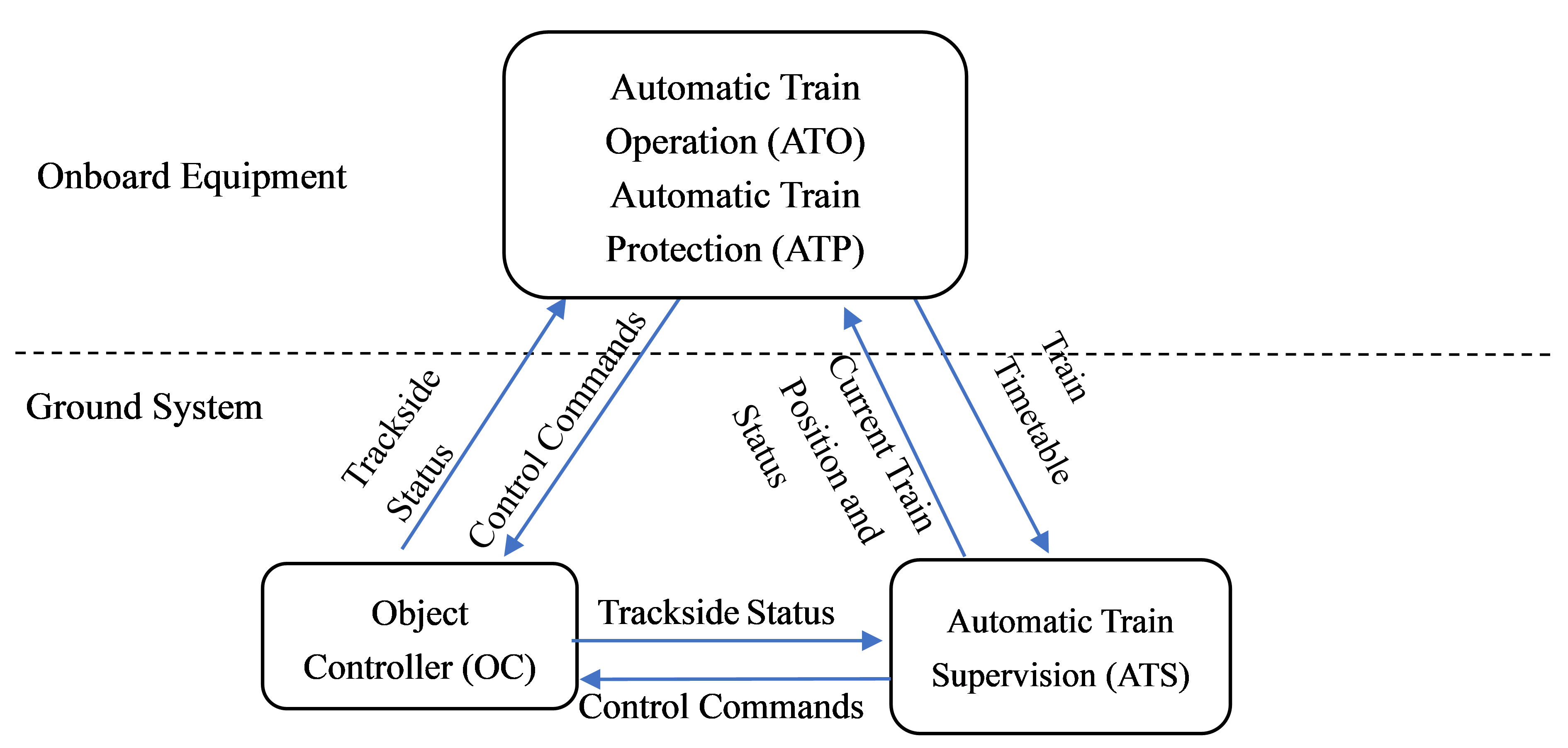
Figure 1. TACS system design.
1.2. System comparison
TACS has been perfected and enhanced in comparison to CBTC systems that are more traditional. In terms of system functioning, operating modes, system components, and interface changes, the following factors are compared:
(1) When it comes to functionality, TACS has maintained its traditional capabilities, which include automatic train monitoring and protection, train identification and tracking, and the creation and maintenance of train timetables. In addition to this, it implements a novel virtual coupling function, modifying the communication technique, which needs direct connection between neighboring trains to acquire information on location and speed.
(2) The TACS model expands upon the capabilities of the CBTC model's continuous ATP and point ATP modes in terms of its operational modes. It introduces additional train control modes such as Standby Mode (SB), Full Supervision Mode (FS), Shunting Mode (SH), Sleep Mode (SL), Isolation Mode (IS), Guided Mode (CO), Visual Mode (OS), Partial Supervision Mode (PS), and Locomotive Signal Mode (CS), in addition to the backup modes of Passive Mode (SM) and Master Control Mode (MDM). Additionally, it presents the Train-Train Communication Mode (TC) for the first time.
(3) When it comes to the components of the system, TACS gets rid of the Computer Interlocking System (CI) and the Zone Controller (ZC) from the ground equipment. However, it keeps the ATP onboard control equipment, the ATO equipment, and the ATS ground automated supervisory system. The OC system is added to the ground equipment as a result of continuing basic control function.
(4) With regard to the modifications that are made to the interfaces, the interface that was previously present between the train control system and the CI and ZC systems has been removed, and a new interface that is present between the train control system and the OC system has been implemented.
3. Ground part
3.1. ATS system
Monitoring train status, automatic train identification and tracking, compilation and management of train timetables, route control, giving train movement directives, monitoring speed restrictions, and equipment control are the primary responsibilities of the ATS system. The system implements the functionality of virtual coupling, which entails developing and issuing virtual coupling scenarios based on the existing train timetable. This functionality allows trains to be coupled virtually without physically connecting them. It is essential to perform real-time monitoring of the operational condition of the virtual coupling, and extra features, such as remote control for central dispatchers, must be made available. Train positioning is accomplished through a collaborative effort between the OC and the ATS system, which has the authority to control and release train occupancy.
3.2. OC equipment
Within the TACS system, it is the duty of the OC to manage the operation and issue control commands to the trackside equipment. The OC is responsible for enabling two-way contact with trains through the use of wireless communication or DCS, as well as collecting the status of trackside equipment and transmitting information to the train. Through the use of the OC, the train is able to control trackside resources such as switches and platform screen doors in accordance with the requirements of the operation. The OC is required to communicate real-time information about trackside resources to the ATS, which will enable the ATS to perform real-time monitoring of trackside equipment. After that, the train is in charge of controlling the running pace. The logic process of OC in the normal scenario is shown in Figure 2.
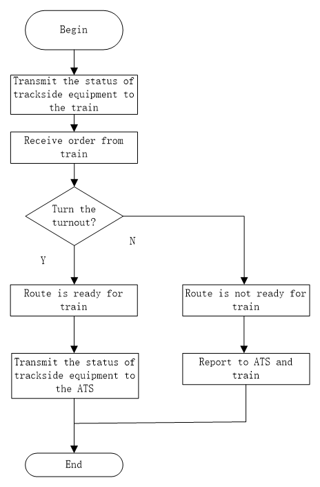
Figure 2. The logic of OC procedure.
After the train control system has successfully and safely released the shared trackside resource status, the OC will only be able to take control and transfer information regarding the trackside equipment to the ATS. The decision to transfer control to the ATS is communicated to the ATS when it has been made to release the control of the OC.
When a particular section develops a fault and trains need to pass through it at a low speed, the OC passes trackside equipment information to the ATS. This is only done in exceptional circumstances where temporary speed limitations are in place. Concurrently, the OC is able to exert immediate control over the shared resources, which makes it possible to appropriately slow down trains at the appropriate times. When the train departs the section and the trackside equipment displays clearance, the ATS will communicate temporary speed limitation directives as well as trackside status information to the OC. The OC is responsible for controlling the platform screen doors after receiving this information, as well as checking to see if the section is clear. In addition, the OC applies the speed restriction for train passing and then provides the updated information to the train, which modifies its movement authorization in accordance with the new information.
4. Onboard system
4.1. Onboard modules
The Automatic Train Protection (ATP) system and the Automatic Train Operation (ATO) system are both contained within the Vehicle On-Board Controller (VOBC) that is part of the CBTC system. The VOBC is responsible for communicating with the ATS, with the assistance of the ATP, controlling the traction, braking, and opening and closing of the train's doors. It does this in order to make sure that the train stays within the bounds of the Movement Authority (MA) that is granted by the train itself. This monitoring takes place in real time and is done continually. If the train's speed is higher than the safe protection speed that was estimated, the train will be put into the braking mode so that it can come to a stop before it reaches the dangerous threshold.
ATO provides centralized control of train operations to ensure safe driving. Based on ATP, it implements automatic train operation, speed adjustment, and train door control according to instructions from the Automatic Train Supervision (ATS) system. The main functions of ATO include: 1) automatic running, controlling train start, traction, cruising, coasting, and braking; 2) automatic departure and on-time operation, automatically initiating train departure and adjusting train running to achieve on-time operation according to departure commands and scheduled stop times from ATS; 3) energy-saving and improved comfort, maintaining train speed within the set speed curve, increasing passenger comfort through smooth driving and precise stopping; 4) precise braking and stopping, achieving accurate stopping based on train speed, predetermined braking rate, and precise calculation of braking distance; 5) automatic door control, automatically controlling train doors based on platform position and precise stopping; 6) unattended operation, achieving driverless train operation in coordination with ATS.
The VOBC implements the train-to-train communication module as part of the train-to-train communication paradigm so that trains can communicate with one another and their immediate surroundings.
Within the ATP subsystem, optimization adjustments have been made to the train-ground control flow in order to improve its performance. The ground-based control devices have been removed, and the onboard ATP subsystem has been given the responsibility of performing the safety protection activities that were formerly performed by the ground-based Central Interlocking (CI) and Zonal Controller (ZC). Monitoring of ground resource conditions, monitoring of previous train positions, fault tolerance achieved by software and hardware redundancy, recording, storage, and problem detection are all made possible as a result of this. The ATO subsystem now includes the virtual coupling function that was previously missing. During the interaction with ATS, the virtual coupling and decoupling functions are implemented. These functions are based on the virtual coupling commands in the train timetable that are issued by ATS, and they take into consideration other factors as well, such as the status of the train's brakes, the current speed, the occupancy of trackside equipment ahead, and the position of the train.
4.2. Train-to-Train communication module
The development of train virtual coupling is the foundation upon which reliable train-to-train communication technology is constructed. Information is passed back and forth between the various modules and sub-modules as part of this process. All pertinent functions in the train-to-train communication mode are dependent on the technology that is onboard. As a result, in addition to the duties that are already performed by the onboard equipment, new functionalities are added. These new functionalities include onboard wireless data connection, train autonomous speed measurement and location, train identity and information protection, and autonomous computation of movement authority. Following the identification of the train that came before it, nearby vehicles that are part of the same virtual coupling can communicate with one another as a train. The following items are included in the prior train identification process:
1. The train uses the onboard communication system to inquire about the state information from the train that came before it. Once it has established its position and begun train-to-train contact with the previous train that is closest to it, the train will determine the answer it received from the train that came before it. Regular updates are made to the communication, and tests are performed to ensure that it is functioning properly.
2. An electronic map model, which functions as the physical basis for train operation and location, must be installed in each and every train that is in operation. It includes fundamental facts as well as information about the various sections of the track. The electronic map module serves as the foundation for determining the location of adjoining trains and the operational status of equipment inside the section.
3. In the train-ground communication mode, the train itself is often responsible for performing calculations about movement authority, train speed measurement and positioning, and train positioning. Train-to-Train Communication (TC) mode, on the other hand, prevents the subsequent train in a virtual coupling from being able to compute and issue movement authority depending on the train that came before it. Because of this, it is necessary for this portion to be carried out independently by the train. Wireless communication, transponders, and wheel sensor devices are utilized in the train in order to accurately determine its speed and position. On the basis of this information, it determines the appropriate safe running distance for each time slot and independently determines the movement authority.
The primary alterations that are made to the operational capabilities of onboard equipment are what are required to bring the structure of the virtual coupling system into compliance with the operational requirements of virtual coupling. The viability of the virtual coupling application can be increased by moving some of the functions that were previously performed on the ground to the equipment that is located aboard. Even though some of the features of the ground-based equipment have been removed, the original CBTC ground-based equipment can be preserved as a backup and triggered in the event of abnormal states occurring during the virtual coupling process. This helps to ensure that the system is backward compatible.
5. Scenario analysis of train-to-train communication
The train-to-train communication scenarios can be classified into four categories: (1) Normal operation scenario, (2) Degraded operation scenario, (3) Emergency operation scenario, and (4) Virtual coupling scenario.
5.1. Normal operation scenario
Train-to-train communication ensures that trains arrive, stop, and depart in accordance with the train timetable when the regular mode of operation is in effect. Trains are put through the train yard's preparation work prior to the commencement of operation, and then they are put through the railway yard's cleaning work after operation.
The normal operation scenario includes the following:
Start of operation: All tasks from system startup to the beginning of operation.
End of operation: All tasks from the end of operation to system shutdown.
Normal operation: Trains operate on the mainline according to the schedule.
Special situations: Abnormal situations such as minor delays, temporary speed restrictions, etc., that deviate from normal operation.
5.2. Degraded operation scenario
The scenario of degraded operations is associated with tasks such as system fault management, operational optimization, and maintenance. The Automatic Train Supervision (ATS) system provides a train timetable, but in this situation, the trains do not obey the ATS timetable. System breakdowns are almost often the cause of scenarios involving degraded operation. Trains continue to operate under the supervision and control of the ATS system even when they are operating according to their own individual sub-timetables. The train's supplemental schedule is devised after careful consideration of a variety of tactics designed to reduce the number of service interruptions brought on by mechanical and technological issues. For instance, if there are mechanical failures in the ground equipment, a train degradation strategy needs to be adopted as soon as possible. When the Automatic Train System (ATS) determines that there is a problem with the train's equipment, the Automatic Train Operation (ATO) system will automatically apply the brakes, produce a new Movement Authority (MA), and send it to the train. The train will either slow down or come to a complete stop once it has received the new, downgraded MA. This will result in an increase in the amount of time that must pass before arriving at the subsequent station.
5.3. Emergency operation scenario
Trains will implement the proper operational procedures in the event of an emergency circumstance such as extreme weather conditions (rain, snow), a power outage, or another accident. In the majority of cases, trains that are involved in emergency circumstances are unable to function automatically and need to be towed to evacuation lines by rescue trains. Because it is necessary to maintain a safe distance, the affected portion has been cut off from the operating part, and it is against the rules for trains to enter the safety distance zone. After the end of the day's operations, the malfunctioning train is dragged away, and then it is taken to the maintenance facility.
5.4. Virtual coupling scenario
The process of converting from moving block operation to virtual coupling operation is referred to as the dynamic coupling process [6]. In the scenario of virtual coupling, the trailing train is required to adopt an acceptable tracking strategy in order to reduce the gap between themselves and the leading train [7,8]. Information such as the location of the coupling section and the identification number of the train that is participating in the coupling are included in the coupling plan. This plan is generated by the central ATS and sent in advance to the Vehicle On-Board Controller (VOBC) located within the coupling section. The VOBC within the coupling section then distributes it to the trains that are participating in the coupling procedure before the process of coupling really begins.
After the dynamic coupling has been successfully accomplished, the train fleet will continue to operate while maintaining the coupling status. The train that is in front of the coupling provides the authority to proceed, and the train that is following it must adopt an acceptable tracking strategy in order to stay synced with the train that is in front of it in order to keep the coupling status. Train-to-train communication is used in the ideal situation so that the trailing train can acquire the running data and speed profile of the leading train. With this information, the trailing train is then able to independently calculate its own speed profile. When determining the movement authorization for the leading train, the VOBC needs to take into account the overall operation status of the entire train fleet. This is because the linked train is longer than the individual trains that make up the fleet. For instance, in a scenario in which the train enters a higher speed limit, once the train length and tracking interval have been determined, the goal speed of the coupled trains reaches a stable value. This occurs in the event that the train enters the higher speed limit. The same thing happens when the train enters an area with a reduced speed limit, which requires maintaining the correct coupling coordination. It is impossible to maintain the optimal coupling distance because speed variances occur during train following and cumulative position deviations increase over time. It is necessary to implement corrective speed adjustments based on real-time separation in order to cut down on accumulated errors in order to achieve the optimal level of train separation. During the operation of tracking the linked train, it is necessary to devise suitable response methods for abnormal scenarios, which may include shifts in the line speed limitations, excessive communication delays, and unanticipated variations in line conditions. Limiting conditions should be imposed on communication delays within a section if it is found to have excessively high communication delays. These delays could potentially affect the reliability of train-to-train communication data or result in dangerous situations due to a lack of updated information on adjacent trains. It is possible for unexpected changes in train speed or an inability to accomplish the intended braking effect to compromise operational safety if it is discovered that there are obstructions on the track, or sharp curves ahead within the working section of the coupling train. Therefore, monitoring the conditions of the line in real time is required in order to modify the needed tracking distance and ensure that the coupled train operates in a safe manner.
6. Conclusion
The architecture, design, and research of a Train-Centric Autonomous Control System (TACS) based on CBTC systems have been given. The conceptual framework of the TACS design has been presented and evaluated in light of the CBTC system. Discussion has taken place on the ground components of the TACS system; nevertheless, the design emphasis has been placed on the onboard modules, the train-to-train communication module, and the newly included ground Operation Control (OC) module. In addition, the virtual coupling scenario in train-to-train communication has been the subject of a comprehensive investigation that has been carried out.
This design not only lays the groundwork for the fundamental architecture of the train-centric automatic control system, but it also serves as a foundation for the functional applications, scenario analysis, and technical implementation of each individual component. In the future, additional study could be carried out in the subject of delay control in train-to-train communication. This research would have to take into consideration particular real engineering circumstances. Continuous efforts to improve the effectiveness of the way train operations are carried out.
References
[1]. Feng, H., Zheng, Z., Bai, G., et al. (2022). Train Working Mode of Train-Centered Autonomous Control System. Urban Mass Transit Research, 25(12), 198-202. (In Chinese)
[2]. Feng, H., Bai, G., Yu, J., Liu, H., & Huang, S. (2022). Study on Functions and Operation Scenarios of Train-Centered Autonomous Control System. Urban Mass Transit Research, 25(10), 115-119. (In Chinese)
[3]. Cao, Y., Wen, J., & Ma, L. (2021). Tracking and Collision Avoidance of Virtual Coupling Train Control System. Alexandria Engineering Journal, 60(2), 2115-2125.
[4]. Bai, J., Zhang, Q., & Lu, F. (2022). Study on Organization Scheme of Virtual Coupling Train for Urban Rail Transit. Urban Rapid Rail Transit, 35(1), 126-133. (In Chinese)
[5]. Yang, A., Sun, J., Wang, B., et al. (2022). Optimization of Train Operation Plan for Cross-Line Trains Based on Virtual Coupling Technology. Journal of Beijing Jiaotong University, 46(4), 9-14. (In Chinese)
[6]. Schumann, T. (2017). Increase of Capacity on the Shinkansen High-Speed Line Using Virtual Coupling. International Journal of Transport Development and Integration, 1(4), 666-676.
[7]. Xun, J., Chen, M., Ning, B., et al. (2019). Performance Measurement of Subway Train Tracking Operation under Virtual Coupling. Journal of Beijing Jiaotong University, 43(1), 96-103. (In Chinese)
[8]. Wang, Y., Liu, L., Liu, J., et al. (2020). Carrying Capacity Calculation Method of Regional Rail Transit Line Based on Flexible Train Formation. In IEEE 23rd International Conference on Intelligent Transportation Systems (pp. 1-6). Rhodes.
Cite this article
Guo,Y. (2023). Design and research of train-centric autonomous control CBTC system. Applied and Computational Engineering,12,260-267.
Data availability
The datasets used and/or analyzed during the current study will be available from the authors upon reasonable request.
Disclaimer/Publisher's Note
The statements, opinions and data contained in all publications are solely those of the individual author(s) and contributor(s) and not of EWA Publishing and/or the editor(s). EWA Publishing and/or the editor(s) disclaim responsibility for any injury to people or property resulting from any ideas, methods, instructions or products referred to in the content.
About volume
Volume title: Proceedings of the 2023 International Conference on Mechatronics and Smart Systems
© 2024 by the author(s). Licensee EWA Publishing, Oxford, UK. This article is an open access article distributed under the terms and
conditions of the Creative Commons Attribution (CC BY) license. Authors who
publish this series agree to the following terms:
1. Authors retain copyright and grant the series right of first publication with the work simultaneously licensed under a Creative Commons
Attribution License that allows others to share the work with an acknowledgment of the work's authorship and initial publication in this
series.
2. Authors are able to enter into separate, additional contractual arrangements for the non-exclusive distribution of the series's published
version of the work (e.g., post it to an institutional repository or publish it in a book), with an acknowledgment of its initial
publication in this series.
3. Authors are permitted and encouraged to post their work online (e.g., in institutional repositories or on their website) prior to and
during the submission process, as it can lead to productive exchanges, as well as earlier and greater citation of published work (See
Open access policy for details).
References
[1]. Feng, H., Zheng, Z., Bai, G., et al. (2022). Train Working Mode of Train-Centered Autonomous Control System. Urban Mass Transit Research, 25(12), 198-202. (In Chinese)
[2]. Feng, H., Bai, G., Yu, J., Liu, H., & Huang, S. (2022). Study on Functions and Operation Scenarios of Train-Centered Autonomous Control System. Urban Mass Transit Research, 25(10), 115-119. (In Chinese)
[3]. Cao, Y., Wen, J., & Ma, L. (2021). Tracking and Collision Avoidance of Virtual Coupling Train Control System. Alexandria Engineering Journal, 60(2), 2115-2125.
[4]. Bai, J., Zhang, Q., & Lu, F. (2022). Study on Organization Scheme of Virtual Coupling Train for Urban Rail Transit. Urban Rapid Rail Transit, 35(1), 126-133. (In Chinese)
[5]. Yang, A., Sun, J., Wang, B., et al. (2022). Optimization of Train Operation Plan for Cross-Line Trains Based on Virtual Coupling Technology. Journal of Beijing Jiaotong University, 46(4), 9-14. (In Chinese)
[6]. Schumann, T. (2017). Increase of Capacity on the Shinkansen High-Speed Line Using Virtual Coupling. International Journal of Transport Development and Integration, 1(4), 666-676.
[7]. Xun, J., Chen, M., Ning, B., et al. (2019). Performance Measurement of Subway Train Tracking Operation under Virtual Coupling. Journal of Beijing Jiaotong University, 43(1), 96-103. (In Chinese)
[8]. Wang, Y., Liu, L., Liu, J., et al. (2020). Carrying Capacity Calculation Method of Regional Rail Transit Line Based on Flexible Train Formation. In IEEE 23rd International Conference on Intelligent Transportation Systems (pp. 1-6). Rhodes.