


1. Introduction
1.1. The purpose and significance of studying the new energy vehicle drive bridge
With the continuous improvement of living standards, cars have gradually become an important transportation of mobility. Traditional cars are driven by gasoline or diesel internal combustion engines. The exhaust emissions are large, the energy consumption is large, and it has large environmental harm [1].
Since the 21st century, the concept of new energy vehicles has been proposed, referring to using unconventional vehicle fuel as a power source, combining new vehicles formed by the vehicle's power control and driving advanced technologies [2]. Compared with traditional gasoline or diesel-driven cars, new energy vehicle exhaust emissions and small energy consumption are small, and the harm to the natural environment is small. Therefore, in today's dilemma of the traditional automobile industry, new energy vehicles are a promising development direction.
In the process of the development of new energy vehicles, optimizing the passenger experience of the car and reducing the energy consumption of the car are two important development directions. Due to the different power, many parts can be optimized and improved compared to traditional vehicles.
Especially for the optimized design of the drive bridge, it can greatly improve the comfort and stability of the ride, but also make the bridge structure lightweight [3], saving power and effectively improving the battery life of new energy vehicles. Therefore, it is not difficult to conclude that the structure optimization of the driving bridge of new energy vehicles and the significance of lightweight research are extremely significant.
1.2. Briefly describe the current situation in China and abroad
New energy vehicles in the world mainly include pure electric vehicles, hybrid vehicles, fuel cell vehicles and other different development routes [4].
China's new energy vehicle sales and preservation volume ranked first worldwide for three consecutive years. The overall development of the new energy vehicle industry has developed rapidly, but compared with the traditional automobile industry, the market share is still low. The main scientific research and development directions of domestic enterprises are concentrated in hybrid vehicles and pure electric vehicles. On a number of indicators such as mileage and comprehensive operating conditions, domestic hybrid vehicles are better than foreign hybrid new energy vehicles. In terms of fuel cell vehicles, there is still a certain gap between China and international advanced levels, mainly in the output power and service life of fuel cells.
Specifically, in terms of the research on the driving bridge, the traditional car-driven bridge has gone through many years of development. There are still shortcomings such as large -volume and low technical content. New energy vehicles need to be lighter to optimize design research than traditional cars. The general technical route of the optimization design of the car driving bridge is: to clarify the purpose of optimization, determine the research objects, analyze the research objects, propose optimization plans, conduct finite element analysis, perform strong school checks, and finally complete the optimization design. This article is mainly based on the driving axle case of new energy vehicles and analyzes the advantages of the layout of the new energy vehicle drive system compared to fuel vehicles.
2. Driving axle case stress analysis
2.1. Mechanics model under various working conditions
During the car driving process, there will be a variety of different operating conditions. This article abstracts a variety of different working conditions into four typical mechanical models, namely: the active conditions of the vertical force (the car is fully loaded and in the static state), the maximum traditional work conditions (The car is fully loaded and started with the maximum traction), braking power conditions (car full load and maximum traction emergency braking), and maximum side -oriented work conditions (car full -load on the side slip) [5].
2.2. Vertical force conditions
As shown in Figure 1, the axle case is like a hollow beam. It relies on the wheel bearing of the wheels at both ends to the wheels, and the load of the car is added to the steel plate spring seat on both sides of the axle case [6]. At the same time, the wheels on both sides are also supported by the support force G2/2 given by the bottom surface. The power of the axle case is the difference between the branches and the gravity of the wheels' gw, that is(G2/2-gw. When the axle case is calculated according to the static load, the curved moment M between its two steel plate spring seats is
\( M=({G_{2}}-{g_{w}})\frac{B-s}{2} N∙m \) (1)
In the formula:
\( {G_{2}} \) —— Driving the bridge to the bottom surface when the car is full on the horizontal pavement (N);
\( {g_{w}} \) ——The gravity (N) of wheels (including wheels and brakes);
B —— drive the wheel distance (m);
s —— Drive the center distance (m) of the two steel plate spring seats on the axle case.
At this time, the maximum vertical force is
\( {F_{2max}}=2.5∙{G_{2}}/2 \) (2)
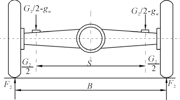
Figure 1. Simple diagram of the active conditions of the vertical force. (Photo/Picture credit: Original)
Maximum traction work conditions
As shown in Figure 2, in order to simplify the calculation, the maximum traction of the car does not consider the side force, that is, at this time, it is calculated only based on the operating conditions of the vehicle in line. At this time, the high heart of the car is recorded as \( {h_{g}} \) .
The maximum tangential reaction force on the left and right drive wheels is
\( {P_{max}}=\frac{{T_{emax}}{i_{g1}}{i_{0}}{η_{T}}}{{r_{r}}} N \) (3)
In the formula; \( {T_{emax}} \) —— the maximum torque of the engine (N \( ∙m \) );
\( {i_{g1}} \) ——The transmission 1 transmission ratio;
\( {i_{0}} \) ——The main slowdown ratio of the driving bridge;
\( {η_{T}} \) ——The transmission efficiency of the transmission system;
\( {r_{r}} \) ——The rolling radius of the wheel (m)
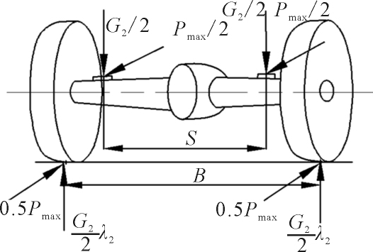
Figure 2. Simple diagram of the maximum traditional work conditions.(Photo/Picture credit: Original)
2.3. Braking force conditions
As shown in Figure 3, when the car is emergency braking, the impact of the side force is ignored. Assuming that the vertical reaction force and the same force of the left and right wheels are equal, then there is
\( {F_{L2}} \) = \( {F_{R2}} \) = \( {G_{2}}{λ_{2}} \) /2(4)
The maximum brakes on the wheels are:
\( {F_{b}} \) = \( {G_{2}}{λ_{2}}φ \) /2(5)
The outside of the spring seat is also affected by torque T:
T= \( {G_{2}}{λ_{2}}φ{r_{r}} \) /2(6)
\( {λ_{2}} \) is the quality transfer coefficient under the emergency system. For small trucks, it is generally 0.75 here;
\( φ \) is the attachment coefficient of the pavement, which is 0.75 here.
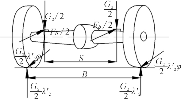
Figure 3. Simple diagram of the braking force conditions.
2.4. The maximum side directional conditions
As shown in Figure 4, when the car is fully on the side of the car, the car is considered to bear the maximum side force (when turning rapidly, when the full load). When the car turns at a full load and a high speed, its quality will produce a considerable centrifugal force, and the car is prone to skids.
The support for the left and right wheels of the car is \( {F_{L2}} \) and \( {F_{R2}} \) :
\( {F_{L2}} \) = \( {G_{2}}(1/2-{h_{g}}{φ_{1}}/B) \) (7)
\( {F_{R2}} \) = \( {G_{2}}(1/2+{h_{g}}{φ_{1}}/B) \) (8)
In the formula: \( {h_{g}} \) is the height of the maximum load of the car; B is the wheel distance of the wheel; \( {φ_{1}} \) is the side attachment coefficient between the tire and the ground, which is 0.7 here.
The side force of the axle case
P2=G2 \( φ \) (9)
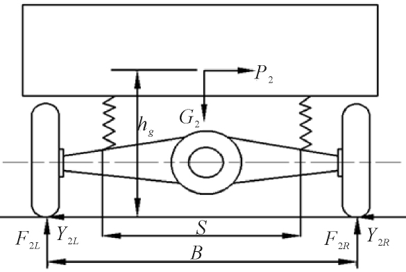
Figure 4. Simple diagram of the maximum side directional conditions.
2.5. Data calculation in various conditions
Table 1. Parameter of a pure electric passenger car table [5].
parameter name | Indication symbol | Value |
Full load quality/kg | \( {M_{1}} \) | 4100 |
Rear shaft load/kg | \( {M_{2}} \) | 3000 |
Maximum torque of the engine/N \( ∙ \) m | \( {T_{emax}} \) | 350 |
Mainly Speed Transmission ratio | \( {i_{0}} \) | 4.5 |
Vehicle rolling radius/m | \( {r_{r}} \) | 0.345 |
Transmission No. Ⅰ gear ratio ratio | \( {i_{gI}} \) | 6.00 |
Auto quality height/m | \( {h_{g}} \) | 0.700 |
Drive wheel wheel distance/m | B | 1.65 |
The center distance of the spring seat on the axle case/m | S | 1.01 |
Output torque/N \( ∙ \) m | T | 8000 |
Maximum speed/km/h | \( {V_{a}} \) | 120 |
The main data used in the data calculation of this article is shown in Table 1.
For vertical force conditions:
\( {F_{2max}}=2.5∙{G_{2}}/2 \) = \( =36750N \) (10)
At the same time, for the maximum traction:
\( {P_{max}}=\frac{{T_{emax}}{i_{g1}}{i_{0}}{η_{T}}}{{r_{r}}} =26022N \) (11)
The vertical force of a single wheel is equal to FL and FR, and there are:
\( {F_{2}} \) /2= \( {G_{2}}{λ_{2}}/2=17640N \) (12)
In the formula:
\( {F_{2}} \) /2 is the vertical force that is applied to a single wheel for the ground;
\( {λ_{2}} \) is the quality transfer coefficient of the normal driving of the car, which is 1.2 here.
The anti -reaction force of the axle case
F2=35280N(13)
Calculation for braking conditions:
\( {F_{L2}} \) = \( {F_{R2}} \) = \( {G_{2}}{λ_{2}}/2=11025N \) (14)
The maximum brakes on the wheels are:
\( {F_{b}}={G_{2}}{λ_{2}}φ/2=8268.75N \) (15)
The torque of the outside of the spring seat is also affected T:
\( T={G_{2}}{λ_{2}}φ{r_{r}}/2=2852.72N \) (16)
For the maximum side force conditions:
Left wheel support force:
\( {F_{L2}}={G_{2}}(1/2-{h_{g}}{φ_{1}}/B)=5969N \) (17)
Right wheel support force:
\( {F_{R2}}={G_{2}}(1/2+{h_{g}}{φ_{1}}/B)=23430N \) (18)
The side force of the axle case:
\( P2=G2φ=20580N \) (19)
For the result of the analysis of the force analysis of the axle case, when the car is full of static, the axle case only withstands the vertical load from the spring seat, and when the car has a full load and starts with maximum traction, the main inspection ground and tires of the driving axle case are given to give it. The vertical reaction force, the vertical force of the spring seat when the car is fully loaded, is less than the vertical force driving in the line, so it should focus on the outer torque that the spring seat bears. When the car is full of side slips, the support force of the axle case is the smallest of the four working conditions, so it mainly examines the side force of the axle case. The force analysis and data calculation of the four typical work conditions can provide important data support and a theoretical foundation for subsequent structural design.
2.6. Different forms of axle case weight and strength comparison
2.6.1. Overall cast/stamping welding
The overall cast axle case is shown in Figure 5. Compared to the axle case produced through stamping and welding, the cast axle case has a greater thickness. Consequently, when the same component is manufactured using the overall casting method, it results in a heavier structure. The intensity of the overall casting component is better than that of stamping parts welded, but at the same time, it also has higher production costs and maintenance costs. As shown in Figure 6, the stamping welded axle case.
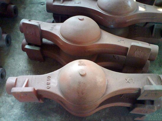
Figure 5. Overall casting axle case [7].
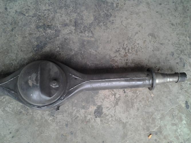
Figure 6. Stamping and welding axle case [8].
2.6.2. Cast iron material/aluminum alloy material
Part Name | Material name | material density/kg/m3 |
Disc brake | ||
Brake disc | HT250 | 6.8-7.3 |
Brake pliers | 45# | 7.85 |
Axle case | malleable iron Cast aluminum alloyZL205A | 7.2-7.4 2.82 |
Main reducer assembly | ||
Differential bevel gear | 20CrMnTi | 7.82 |
Bilateral gear | 20CrMnTi | 7.82 |
Table 2. Driven bridge assembly material part of the parameter table [9, 10].
It can be seen from Table 2 that the density of cast iron material is much higher than that of aluminum alloy material (nearly three times). At the same time, the strength and stiffness of cast iron are also higher, and the ability to bear severe impact and long-term high-strength load is strong, but its disadvantage is poor heat dissipation performance. The aluminum alloy material has good heat dissipation, low density and strong corrosion resistance. The disadvantage is that the cost is higher than that of cast iron (the price of cast iron of the same quality is about 35% of that of aluminum alloy material) [11].
Due to the development of disc brakes for many years, there are a series of mature products in the market. Considering the economy and structure, cast iron is selected as the main material.Therefore, to optimize the selection of axle materials for new energy vehicles, the main consideration is to replace the axle housing materials with aluminum alloy materials on the premise of meeting the strength and life requirements.At present, the most widely used aluminum alloy brands are high-strength cast aluminum alloys ZL205A, ZL401, etc.
3 Differences between pure electric vehicle drive axle and fuel vehicle
The main difference between pure electric vehicles and fuel vehicles is that the motor of electric vehicles replaces the fuel engine and fuel tank of fuel vehicles, so the other systems of the vehicle, including steering, drive, braking and other systems, are roughly the same, that is, the structure of the vehicle's drive axle, reducer, differential and so on is universal [12].
Figure 7 is a schematic diagram of the drive system of a pure electric vehicle, and Figure 8 is a schematic diagram of the drive system of a fuel vehicle:
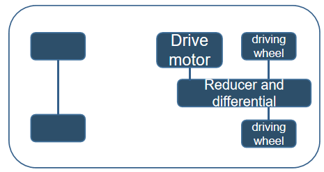
Figure 7. Schematic diagram of pure electric vehicle drive system. (Photo/Picture credit: Original)
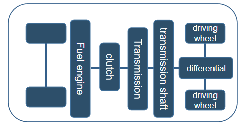
Figure 8. Schematic diagram of fuel vehicle drive system. (Photo/Picture credit: Original)
As depicted in Figure 8, within the conventional propulsion system of a fuel-powered vehicle, the inclusion of the internal combustion engine's transmission is crucial. This component plays a vital role in conjunction with the clutch, ensuring the smooth initiation of the vehicle's movement and preventing potential engine stalling resulting from excessive starting load. Compared to the internal combustion engine, the motor's input power exerts a more pronounced influence on the dynamic characteristics of a vehicle. Moreover, it eliminates the need for a no-load start to reach the operational speed, which is required for internal combustion engines [13]. Consequently, pure electric vehicles do not require a physical gearbox. Consequently, the driving system of pure electric vehicles experiences significant simplification when compared to traditional fuel-powered vehicles. In terms of riding experience, although the drive axle of pure electric vehicles is universal with traditional fuel vehicles in theory because the motor volume of pure electric vehicles will occupy less space than the power system of fuel vehicles, the impact of the layout of the drive axle on the internal space of the vehicle will be greatly reduced, which is more conducive to the improvement of the layout of the drive system to improve the ride comfort.
4 Conclusion
In summary, research and development of new energy vehicles is the current and development trends of automobiles. This paper analyzes the research background, determines the research object, simplifies and summarizes the stress of the axle housing, calculates the data, and finds out the main force objects of the axle housing under different conditions: when the vehicle is fully loaded and stationary, the vertical force on the axle housing is mainly investigated, while when the vehicle is fully loaded and starts with the maximum traction force, the vertical reaction force given by the ground and tires is mainly investigated, and when the vehicle is fully loaded and braked, Focus on the external torque borne by the spring seat. When the vehicle skids with full load, the lateral force on the axle housing is mainly investigated. The analysis results are of great significance for the subsequent in-depth study of the optimal design of the drive axle of new energy vehicles.
Finally, this paper also makes a comparative analysis of the drive system layout of pure electric vehicles and traditional fuel vehicles, discusses the differences between the drive system of pure electric vehicles and traditional fuel vehicles, and finds that the optimized pure electric vehicle drive system has obvious advantages in lightweight and riding comfort. The optimal layout of the drive system and the optimization of the material and structure of the drive axle body will become two important directions in the optimization research of the drive axle of new energy vehicles.
References
[1]. Lin LH, Li YL, Li CB, Zhao LJ 2019 Lightweight design of pure electric vehicle drive axles, Journal of Chongqing University, vol 42(2) p17-28
[2]. Tian CL. Automotive Manufacturing Industry 2020 vol 654 (05) p16-19
[3]. Liu WX 2003 Automotive Axle Design, Tsinghua University Press
[4]. Huang SG, Xu YC, Zou BF 2021 Automotive Technologist (06) p 50-53
[5]. Huang FY, Zhou K 2017 Digital Manufacturing Science, 15 (03) p 103-107+113
[6]. Zheng Q 2013 New Energy Vehicle Drive Axle Anhui Province, Anhui Agricultural University, p11-24
[7]. Chen HW 2019 Differences and Advantages and Disadvantages between Truck mounted Crane Cast Bridge and Punch Welded Bridge, vol 3, p14
[8]. Hebei Haishi Machinery Co., Ltd. Haishi BJ212 Axle Housing Assembly
[9]. Zhao B, Lu XQ 2023 Drive axle final drive housing Shaanxi Province: CN307768662S, January 3
[10]. Sun YF 2010 New Handbook of Non ferrous Metal Materials,China Machinery Industry Press,
[11]. Zeng ZM 2003 Handbook of Mechanical Engineering Materials, Mechanical Industry Press
[12]. Di J, Jin D, Wang ZZ, Wang JH 2020 IOP Conference Series: Earth and Environmental Science, vol 546(5).
[13]. BYD Company Limited 2018 Electronics Newsweekly
Cite this article
Song,J. (2023). Analysis of the force of new energy vehicle drive bridge. Applied and Computational Engineering,12,271-279.
Data availability
The datasets used and/or analyzed during the current study will be available from the authors upon reasonable request.
Disclaimer/Publisher's Note
The statements, opinions and data contained in all publications are solely those of the individual author(s) and contributor(s) and not of EWA Publishing and/or the editor(s). EWA Publishing and/or the editor(s) disclaim responsibility for any injury to people or property resulting from any ideas, methods, instructions or products referred to in the content.
About volume
Volume title: Proceedings of the 2023 International Conference on Mechatronics and Smart Systems
© 2024 by the author(s). Licensee EWA Publishing, Oxford, UK. This article is an open access article distributed under the terms and
conditions of the Creative Commons Attribution (CC BY) license. Authors who
publish this series agree to the following terms:
1. Authors retain copyright and grant the series right of first publication with the work simultaneously licensed under a Creative Commons
Attribution License that allows others to share the work with an acknowledgment of the work's authorship and initial publication in this
series.
2. Authors are able to enter into separate, additional contractual arrangements for the non-exclusive distribution of the series's published
version of the work (e.g., post it to an institutional repository or publish it in a book), with an acknowledgment of its initial
publication in this series.
3. Authors are permitted and encouraged to post their work online (e.g., in institutional repositories or on their website) prior to and
during the submission process, as it can lead to productive exchanges, as well as earlier and greater citation of published work (See
Open access policy for details).
References
[1]. Lin LH, Li YL, Li CB, Zhao LJ 2019 Lightweight design of pure electric vehicle drive axles, Journal of Chongqing University, vol 42(2) p17-28
[2]. Tian CL. Automotive Manufacturing Industry 2020 vol 654 (05) p16-19
[3]. Liu WX 2003 Automotive Axle Design, Tsinghua University Press
[4]. Huang SG, Xu YC, Zou BF 2021 Automotive Technologist (06) p 50-53
[5]. Huang FY, Zhou K 2017 Digital Manufacturing Science, 15 (03) p 103-107+113
[6]. Zheng Q 2013 New Energy Vehicle Drive Axle Anhui Province, Anhui Agricultural University, p11-24
[7]. Chen HW 2019 Differences and Advantages and Disadvantages between Truck mounted Crane Cast Bridge and Punch Welded Bridge, vol 3, p14
[8]. Hebei Haishi Machinery Co., Ltd. Haishi BJ212 Axle Housing Assembly
[9]. Zhao B, Lu XQ 2023 Drive axle final drive housing Shaanxi Province: CN307768662S, January 3
[10]. Sun YF 2010 New Handbook of Non ferrous Metal Materials,China Machinery Industry Press,
[11]. Zeng ZM 2003 Handbook of Mechanical Engineering Materials, Mechanical Industry Press
[12]. Di J, Jin D, Wang ZZ, Wang JH 2020 IOP Conference Series: Earth and Environmental Science, vol 546(5).
[13]. BYD Company Limited 2018 Electronics Newsweekly