


1. Introduction
UART converts 5 parallel data with serial data transmitted when data is sent, and converts received serial data to parallel data when receiving data, which can perform full duplex transmission and reception. Its versatility is reflected in the wide range of UART usage, as a general interface protocol, UART is widely used in all kinds of MCU and SOC products; its asynchronous nature is reflected in the fact that "no extra clock line is needed for synchronous data transmission", that is, as long as the signal is pulled low, data transmission can start, while some other communication protocols Other communication protocols require the introduction of a clock signal for operation.
From the perspective of transmission media, communication can be divided into two types: wired communication and wireless communication [1]. With the rapid development of information technology today, embedded devices based on UART can easily achieve wired and wireless communication through various communication interfaces or with the help of various wireless modules. In the research and application of UART, many engineering technicians and researchers have designed various application schemes. Aiming at the frame format of the serial interface signal of a single chip computer, a communication scheme that can directly modulate/demodulate it is designed and implemented. For example, scholars have designed a design method of temperature acquisition module based on RS485 field bus. Wireless communication based on STM32 is realized using a Wi Fi wireless module and UART, and data is transmitted and received through the upper computer. UART is widely used in engineering applications [2]. Finally, we designed a simple simulation based on the principle of UART independently and read other literature to review two advanced uses and designs on UART.
2. Transmission speed
UART is used to achieve asynchronous communication between two devices, namely, a universal serial asynchronous full duplex data transceiver [3]. Universal asynchronous transceiver device architecture. In this communication mode, different transmission paths are used for sending and receiving serial data, and the two transmission paths can simultaneously conduct data reception and transmission processes, namely, a full duplex two-way transmission communication mode.
The working principle of UART is to convert data conforming to the universal asynchronous data transmission frame format into bit one Bit by bit sequential transmission, and the character bit transmission sequence is in the small end transmission from the low bit to the high bit. In UART serial communication, the baud rate is commonly used as a measurement unit to characterize the data transmission rate, which represents the number of symbol symbols transmitted per second, and the unit is bps. Because UART is an asynchronous communication method, when the transceiver performs UART serial communication, it is necessary to configure the baud rate in advance to be consistent. At the same time, on the basis of ensuring correct baud rate matching between the transmitter and receiver, it is also necessary to clarify the data transmission frame format [4]. Bit rate and baud rate are terms commonly used in digital communications. The bit rate I is numerically related to the baud rate S as [5]:
\( I=S·{log_{2}}{N} \) (1)
Where N is the amount of information carried by each symbol. The relationship between baud rate and bit rate can also be converted to bit rate = baud rate × the number of binary bits corresponding to a single modulation state [6]. In asynchronous serial communication, the NRZ method is used for data encoding [7], and each binary bit has only 2 states: "0" or "1", which can be calculated by substituting into equation (1).
\( I=S·{log_{2}}{2}=S \) (2)
From equation (2), it can be seen that the bit rate and baud rate are equal for asynchronous serial communication using NRZ coding method [8]. Therefore, by measuring the minimum bit-width time of data in asynchronous serial communication, the bit rate of asynchronous serial communication can be deduced as equivalent to the baud rate of asynchronous serial communication obtained.
3. Serial communication
In modern technology, communication can be divided into parallel communication and serial communication. And Serial communication can be further subdivided.
3.1. Classification of communication
3.1.1. Serial communication. Serial communication means that each of the data transmission between the computer and the I/O device are transferred sequentially, one after the other. Serial communication has a slow transmission speed, but the transmission equipment used is low cost and can use the existing means of communication and communication equipment that is suitable for remote computer communication.
3.1.2. Parallel communication. When data is delivered simultaneously over numerous transmission lines from the computer to the I/O port device, this is referred to as parallel communication. Parallel communication is fast but the cost of the transmission equipment used is high, and it is suitable for data transmission in close proximity. And because of the advantages of serial communication and the compensation of the disadvantages, it leads to the basic use of serial communication in today's communication.
3.2. Classification of serial communication
3.2.1. The presence of a synchronous. If judged by the presence of a synchronous clock, serial communication is divided into synchronous and asynchronous communication. Synchronous communication means with clock synchronization signal, the sender and receiver under the control of the same clock, to achieve synchronous transmission; asynchronous communication means without clock synchronization signal, using their own clock control but requires both parties to mutually agree on the data transmission rate.
3.2.2. The direction of data transmission. If judged according to the direction of data transmission, serial communication is divided into simplex, half-duplex and full-duplex communication. Simple communication, data transmission only along one direction, cannot achieve two-party communication, such as television, radio; half-duplex communication, data can be transferred along two directions, but at the same time data can only be transmitted in one direction, such as intercom; full-duplex communication, data can be transmitted along two directions, can be carried out at the same time, such as cell phones, telephones.
4. Structure and working principle of UART
UART is a common hardware-to-hardware communication protocol used in computers, microcontrollers, and embedded systems. In existing communication protocols, UART uses only two lines for the sender and the receiver. Although this communication protocol is widely used in today's technology, it cannot be fully optimized in use: when using UART modules inside microcontrollers, there is no guarantee that the frame protocol will be implemented correctly [6]. Table 1 summarizes the mandatory information for the UART.
Table 1. Overview of the UART.
Conductors | 2 |
Baud rate | 9600,19200,38400,57600,115200, etc. |
Transmission method | Asynchronous |
Maximum number hosts | 1 |
Maximum number slaves | 1 |
4.1. Transmitter and receiver for UART
Usually, every UART device is divided into two signals: transmitter (Tx) and receiver (Rx). As shown in Figure 1. They are mainly used for data transmission and reception of serial communication and play the role of data transfer.
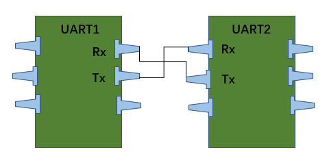
Figure 1. The two UARTs communicate directly with each other.
The transmission rule of UART is parallel communication - serial communication - parallel communication. the UART sender extracts the data from the control data bus in parallel and transmits it to the UART receiver in a serial way through the UART line. Similarly, the UART receiver then transmits the serial data to the data bus at the receiver in parallel communication. Note that UART devices have transmit and receive pins that are intended to either transmit or receive. UART is mainly responsible for processing serial to parallel conversion of parallel data on the bus and serial data between serial ports and specifying the format of data transmission frames [7]. As shown in Figure 2. Both communication parties need to match the data transmission format and baud rate in advance to achieve serial communication using only the receiving and sending data lines under different clock signals, which is also known as asynchronous communication. Because the clocks of both the transmitter and receiver are asynchronous and asynchronous, a frequency doubling clock is used for data sampling to ensure the accuracy of the transmitted data.
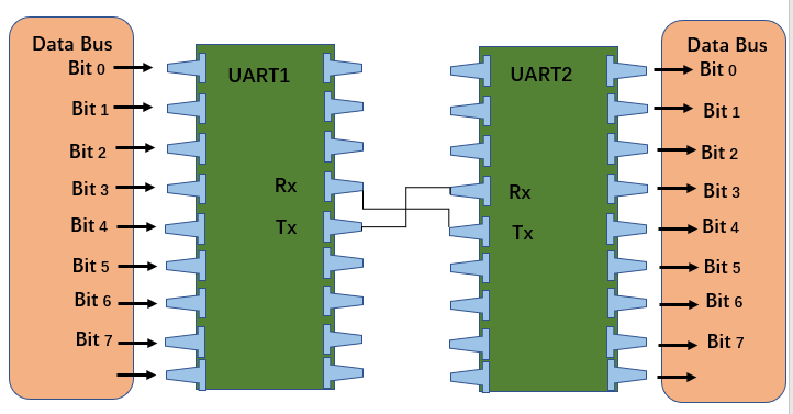
Figure 2. UART with data bus.
4.2. UART communication protocol frame format
For the UART standard data transfer format, the bit width of valid data is up to 8 bits, so that even if each number.
Each data bit has a clock error, and the receiver can also accurately sample data bits, greatly improving the reliability and anti-interference ability of asynchronous communication. During the sampling process of received data, the sampling point is located in the middle of each data bit, and data sampling is conducted every 16 sampling clocks [8]. This sampling method can effectively avoid edge distortion at both ends of the data bit, and avoid errors caused by incomplete synchronization of asynchronous clocks between the transmitter and receiver.
A serial packet's fundamental elements are as shown in Figure 3:
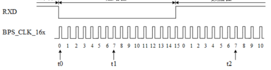
Figure 3. UART data transfer format.
4.2.1. Start bit. Start Bit: T "When using UART to transmit data, there is no uniform clock between the receiving party and the sending party. If the sending party directly sends data, it may cause data transmission errors when receiving data. Therefore, it is necessary to add a flag bit to start data transmission.". UART uses TX line when transmitting data and RX line when receiving data. Both TX and RX are in the idle state without data transmission, and the bus is at high level. Therefore, a low level appears on the UART line in the idle state, indicating that data can be received. If the data receiver detects a low level after the stop bit or in the idle state, it indicates that data needs to be received [9].
4.2.2. Data bit. Data bits: The data frame needs to send the actual data. Data frames can be 5-8 bits long (using parity bits) or 9 bits long (no parity bits). 7-bit ASCII and 8-bit extended BCD codes are good examples. Data is often delivered with the least important bit priority.
4.2.3. Parity bit. Parity bit: In parity check, it is necessary to check whether the number is odd or even. the UART receiver uses this step to analyze and judge the transmitted data and determine whether its data has changed. During the transmission, the data may change due to many factors. For example, errors caused by long time transmission, uneven baud rate, and the effect of electromagnetic radiation.
4.2.4. STOP bit. Because of the interdependence of each device clock and because of the synchronous transmission of data on the transmission line, there is a great possibility of varying degrees of slight desynchronization between devices. Therefore, the stop bit can in fact also help the computer with clock synchronization improvements. The synchronization of the various clocks is more fault-tolerant when additional bits are applied to the stop bit, but at the same time, the data transfer rate decreases.
4.2.5. Idle bit. Idle bit: can be a logic 1 (high) of 1/1.5/2 bits to indicate that no data is currently being transmitted on the line.
4.3. Data transfer process of UART
4.3.1. Sending data process. As shown in Figure 4. In sleep mode, the line is at a high level. When the send command is received, pull one data bit from the line for time T. The transmitting UART receives data from the data bus in parallel by adding a start bit, a parity bit and an end bit to the data frame. After sending the data in order from low to high, the parity bit and the stop bit are transmitted, and the transmission of a single data frame is then complete.
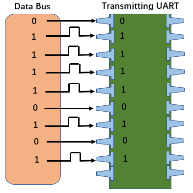
Figure 4. Data bus to transmit UART.
4.3.2. Data reception process. The entire packet is sent serially from the sending UART to the receiving UART from the start bit to the end bit. in idle mode the line is high. When a line shows a falling edge (high to low), data is being transferred and is being received at a predetermined baud rate from low to high. Once the data is received, it is received and compared to see if the parity bit is correct, and if it is correct, the next device is notified to receive the data or store it in a buffer, convert it to parallel data, and send it to the data bus on the receiving side [10].
4.3.3. Transmission baud rate. Since the UART is an asynchronous transmission and does not transmit a synchronous clock, to guarantee the accuracy of the data, the UART uses a clock with 16 times the data rate for sampling. In order to prevent sample skew or miscoding, each data set comprises 16 clock samples, and the middle sample value is used. As there are typically 8 data bits in a UART frame, the receiver can still sample the data accurately even if there is one clock mistake per data bit.
4.3.4. Receiving timing. The receiving module includes a receiving shift register and a receiving control module. The core design idea of the reception control module is to achieve correct sampling and reception of serial data frames through the jump of finite state machines, and perform corresponding operations for unreasonable data frames, such as discarding the data frame or generating corresponding error interrupts [11]. Under the action of the baud rate clock, after the state machine is started, the start bit detection is started on the RX line. After determining that the start bit is valid, the data frame is received bit by bit. After receiving, the data bits in the data frame are sent in parallel to the receive data register. When receiving a data frame, the receiver needs to perform a correctness check on the data frame, including parity bit detection and stop bit check. If an error occurs, a corresponding interrupt signal is generated.
4.3.5. Frame Protocol. There is no doubt that the transmission rules of UART are strictly enforced by its framing protocol. The implementation of the framing protocol is important because it provides protection for each device and ensures the security of the device and data. Failure to properly follow the framing protocol can have serious consequences. For instance, connecting to the same UART without first validating the setup and connecting the devices to distinct pins is conceivable when two devices utilize the same UART framing protocol. This situation can result in system failures.
Alternatively, establishing a framing protocol assures security because the information received must be parsed in accordance with the framing protocol's architecture. Each frame protocol is specifically created to guarantee safety and uniqueness [8].
5. Simple UART simulation
In the above section, we introduced the process and working principle of UART to transmit data. Based on its principle, we design the transmit and receive modules, and implement the baud rate generation and data sending and receiving respectively within their respective modules. As shown in Figure 5 and 6.
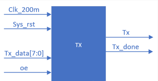
Figure 5. UART transmitter.
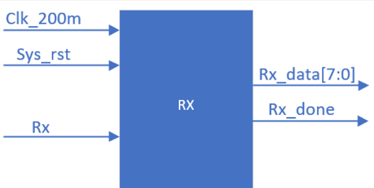
Figure 6. UART receiver.
After performing the simulation of UART, we get its simulation waveform graph. As shown in Figure 7.
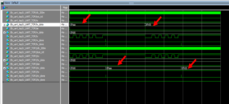
Figure 7. UART simulation waveform.
As shown in the figure 7, TOP/tx is the transmitter and TOP2/rx is the receiver. top/tx_data is the data sent by the transmitter and TOP2/rx_data is the data received by the receiver [12]. The ports TOP/tx_done, TOP/rx_done, TOP2/tx_done, and TOP2/rx_done are used to display the end bits. (The waveform is displayed as a small green line on the right side). The displayed place indicates the end of a frame, that is, the end of the stop bit, when a frame of UART ends and the receiver finishes receiving data. Take TOP/tx as an example. According to the principle of UART frame format, the first low level in the waveform is the start bit; after that, the high or low level data bit starts; after the data bit ends, it is the parity bit; and the last high level is the stop bit, at which time the receiver side finishes the data reception of a frame. After that, the transmitter keeps the idle bit high until the next data is sent. As can be seen from the figure, 8'haa of TOP/tx_data at the first place is transmitted to the receiver side and remains there. And after the transmitter sends 8'h55, it is successfully received by the receiver after one frame and becomes 8'h55.
6. Determination of UART receiver baud
For proper use of the communication function, the transmitter and receiver of the UART protocol must be configured with the same baud rate. The same functionality is achieved by implementing some clock dividers both inside and outside the module. But it is quite possible that the two communicating devices use distinct baud rate clocks, even though the clock dividers have been correctly configured, resulting in a mismatch between the baud rates implemented by the two devices, which can lead to bit corruption at the receiver. There are two main reasons why this baud rate mismatch occurs. Inaccurate baud clocks. Next, we describe a method proposed by Amrit Singh, Khushboo Gupta, and Juhee Mala that describes the determination of an acceptable difference between the transmitter and receiver baud rates for error-free communication via UART [13].
6.1. Data bit sampling for UART
To reduce baud rate errors and improve immunity to errors, the UART has a baud clock (at a baud rate well above the UART) to control all its data transfer operations. With this high baud rate clock operating, the UART's receiver samples the data at a higher baud rate.
The receiver's internal shift register receives the bits of a data frame and shifts them there. If a noise error or frame error is discovered during reception, it is flagged in the protocol according to the implemented error reporting mechanism and appropriate measures are taken according to the type of error. [14].
6.2. UART data transmission bit corruption
The baud rate at which the UART transmitter device operates is probably higher or lower than that of the UART reception device. The receiver CSPs may therefore deviate from the real bit timings as a result of an accumulation of bit time mismatches within the frame. This will cause bit mis-sampling at the receiving end, which will cause corrupted data to be received.
According to the authors' analysis, for error-free reception of a data frame, the csp (Configurable Sample Points) of a bit in the frame (the decisive sampling number configured in the UART receiver) must lie between the first and the last sampling of that bit. After that, the authors analyze the bit corruption and its causes for two cases: Receiver baud rates that are higher than transmitter baud rates and lower than transmitter baud rates.
6.3. Mathematical derivation of the baud rate tolerance
As described by the authors, the CSP is the critical sampling point used to interpret the state of the bits in the data frame. The authors take into account a "nbit" data frame with each bit sampled multiple times OSR, i.e. oversampling equals OSR, in order to construct the mathematical equation to calculate the baud rate tolerance between two UART devices [15].
So, the total number of samples in n-bit UART data frame required for an error free reception:
\( [((n+1)×OSR)+{CSP_{m}}] \) (3)
where, \( {CSP_{m}} \) is
\( {CSP_{m}}=\begin{cases} \begin{array}{c} (\frac{{CSP_{c}}+1}{2})th sample of CSP, when {CSP_{c}} is odd \\ (\frac{{CSP_{c}}+2}{2})th sample of CSP, when {CSP_{c}} is even \end{array} \end{cases} \) (4)
and, \( {CSP_{c}} \) is the number of CSP samples, i.e. the number of configurable sampling points (CSP).
6.3.1. Maximum baud rate tolerance when the baud rate of the receiver is lower than the baud rate of the transmitter. The maximum error tolerance in percent:
\( \frac{[OSR-{CSP_{m}}]×100}{[(n+2)×OSR]} \) (5)
6.3.2. The maximum baud rate tolerance when the receiver baud rate is higher than the transmitter baud rate. The maximum error tolerance in percent:
\( \frac{[{CSP_{m}}-{CSP_{n}}]×100}{[(n+1)×OSR+{CSP_{m}}]} \) (6)
Here, \( {CSP_{n}} \) is
\( {CSP_{n}}=\begin{cases} \begin{array}{c} (\frac{{CSP_{c}}+1}{2}), when {CSP_{c}} is odd \\ (\frac{{CSP_{c}}+2}{2}), when {CSP_{c}} is even \end{array} \end{cases} \) (7)
6.4. Conclusion
The authors show through case studies and experiments that error-free communication between devices can be ensured by properly configuring the baud rate at both ends of the device before connecting two devices in UART mode for communication.
7. Determination of UART receiver baud
The transmission shift register and transmission control in UART jointly implement the transmission function of UART. In order to correctly implement the transmission function, the core design idea of the transmission module is to achieve the correct transmission of data frames through the jump of the finite state machine. Under the action of the baud rate clock, after the state machine is started, it will determine whether there is data to be transmitted in the receive data register. The transmit shift register will receive the data to be transmitted in the TDR, add start bits and stop bits before and after the data, and add parity bits if necessary to form a complete data frame. Finally, the data frame will be sent serially bit by bit through the TX interface. The state machine can jump to different sub states according to different jump conditions to achieve different modes of data transmission.
The frequency divider's function in this case is to allow us to use it in locations where a lower frequency is required to run the function. This frequency divider makes necessary adjustments automatically. The oversampling method essentially ends the operation of the clock signal. It estimates the center of each bit using a sampling scale rather than a rising edge to show when the input signal is legitimate. Due to oversampling, the baud rate could only be only a small portion of the system clock frequency, so this method is not suitable for high data transfer rates[16]. The method used by the authors is to set the receive baud rate to 9600 baud and then pause for the terminal to receive a character. The baud rate affects how long T takes to send each bit. In detection mode, the transmitter receives a carriage return character (0x0D) at 9600 baud. If the transmitter sends a character that is not at 9600 baud rate. Because it divides the input frequency by two now,. The frequency is divided using a frequency divider in accordance with the needs of the system [17]. The authors present a software implementation of input data baud rate detection with simulations. Any microcontroller, microprocessor, or UART device having a baud rate generator and an asynchronous serial port can implement this protocol. If data is sent at 9600 baud rates, the same data will be received at the receiving end if the same baud rate is set. When a different baud rate is selected for the transmitter, as shown in the simulation outcomes, it receives (sample) data from the transmitter in a different state.
8. Conclusion
The full name of UART is Universal Asynchronous Receiver Transmitter, which can meet the requirements of low speed serial communication between devices . UART is a serial communication interface that can transmit serial data bit by bit. This bus can achieve two-way communication. The transmitter and receiver have independent control bits, thereby achieving full duplex data transmission. It is widely used in microprocessors and computers. In microprocessors, UART is generally integrated into the peripheral devices of microprocessors, used for communication between the host and auxiliary devices, and is the main device for realizing serial communication in computers.
References
[1]. Fang Y, Chen X. Design and simulation of UART serial communication module based on VHDL[C]//2011 3rd International Workshop on Intelligent Systems and Applications. IEEE, 2011: 1-4.
[2]. Laddha N R, Thakare A P. A review on serial communication by UART[J]. International journal of advanced research in computer science and software engineering, 2013, 3(1).
[3]. Daraban M, Corches C, Taut A, et al. Protocol over UART for Real-Time Applications[C]//2021 IEEE 27th International Symposium for Design and Technology in Electronic Packaging (SIITME). IEEE, 2021: 85-88.
[4]. Patel N, Patel V, Patel V. VHDL implementation of UART with status register[C]//2012 International Conference on Communication Systems and Network Technologies. IEEE, 2012: 750-754.
[5]. Varghese S G, Kurian C P, George V I. A study of communication protocols and wireless networking systems for lighting control application[C]//2015 International Conference on Renewable Energy Research and Applications (ICRERA). IEEE, 2015: 1301-1306.
[6]. Milenković A, Otto C, Jovanov E. Wireless sensor networks for personal health monitoring: Issues and an implementation[J]. Computer communications, 2006, 29(13-14): 2521-2533.
[7]. Sharma P, Kumar A, Kumar N. Analysis of UART Communication Protocol[C]//2022 International Conference on Edge Computing and Applications (ICECAA). IEEE, 2022: 323-328.
[8]. Kashyap B, Ravi V. Universal Verification Methodology Based Verification of UART Protocol[C]//Journal of Physics: Conference Series. IOP Publishing, 2020, 1716(1): 012040.
[9]. Liu K, Yang M, Ling Z, et al. On manually reverse engineering communication protocols of Linux-based IoT systems[J]. IEEE Internet of Things Journal, 2020, 8(8): 6815-6827.
[10]. Sudhakar A, Rajendra C, Ashok S. Implementation architecture of IEC 60870-5-103 communication protocol on arm platform running on RTOS for industrial IEDs[C]//2022 4th International Conference on Inventive Research in Computing Applications (ICIRCA). IEEE, 2022: 80-86.
[11]. Poutiainen P. Protocol Inspection Toolkit Design for Serial Communication Protocols[D]. , 2020.
[12]. Abdulhamid M, Victor K. Patient health monitoring system based on zigbee communication protocol[J]. Imam Journal of Applied Sciences, 2019, 4(2): 49.
[13]. Ivanov V K, Nosov E V. Serial communication protocol for FPGA-based systems[C]//Journal of Physics: Conference Series. IOP Publishing, 2019, 1326(1): 012044.
[14]. Gupta A, Gupta A. UART communication[J]. The IoT hacker's handbook: a practical guide to hacking the Internet of things, 2019: 59-80.
[15]. Li J, Yang L, Feng X, et al. UART Controller with FIFO Buffer Function Based on APB Bus[C]//2022 IEEE 16th International Conference on Anti-counterfeiting, Security, and Identification (ASID). IEEE, 2022: 1-4.
[16]. MISHRA M. DESIGN AND IMPLEMENTATION OF UART USING VERILOG[D]. , 2022.
[17]. Lavgi P, Kora M L. Patient Health Monitoring System using CAN Protocol[J]. International Research Journal of Engineering and Technology, 2019, 6: 394-398.
Cite this article
Gong,J.;Guo,W.;Sun,W. (2023). UART communication protocol frame format explanation and application. Applied and Computational Engineering,14,47-56.
Data availability
The datasets used and/or analyzed during the current study will be available from the authors upon reasonable request.
Disclaimer/Publisher's Note
The statements, opinions and data contained in all publications are solely those of the individual author(s) and contributor(s) and not of EWA Publishing and/or the editor(s). EWA Publishing and/or the editor(s) disclaim responsibility for any injury to people or property resulting from any ideas, methods, instructions or products referred to in the content.
About volume
Volume title: Proceedings of the 5th International Conference on Computing and Data Science
© 2024 by the author(s). Licensee EWA Publishing, Oxford, UK. This article is an open access article distributed under the terms and
conditions of the Creative Commons Attribution (CC BY) license. Authors who
publish this series agree to the following terms:
1. Authors retain copyright and grant the series right of first publication with the work simultaneously licensed under a Creative Commons
Attribution License that allows others to share the work with an acknowledgment of the work's authorship and initial publication in this
series.
2. Authors are able to enter into separate, additional contractual arrangements for the non-exclusive distribution of the series's published
version of the work (e.g., post it to an institutional repository or publish it in a book), with an acknowledgment of its initial
publication in this series.
3. Authors are permitted and encouraged to post their work online (e.g., in institutional repositories or on their website) prior to and
during the submission process, as it can lead to productive exchanges, as well as earlier and greater citation of published work (See
Open access policy for details).
References
[1]. Fang Y, Chen X. Design and simulation of UART serial communication module based on VHDL[C]//2011 3rd International Workshop on Intelligent Systems and Applications. IEEE, 2011: 1-4.
[2]. Laddha N R, Thakare A P. A review on serial communication by UART[J]. International journal of advanced research in computer science and software engineering, 2013, 3(1).
[3]. Daraban M, Corches C, Taut A, et al. Protocol over UART for Real-Time Applications[C]//2021 IEEE 27th International Symposium for Design and Technology in Electronic Packaging (SIITME). IEEE, 2021: 85-88.
[4]. Patel N, Patel V, Patel V. VHDL implementation of UART with status register[C]//2012 International Conference on Communication Systems and Network Technologies. IEEE, 2012: 750-754.
[5]. Varghese S G, Kurian C P, George V I. A study of communication protocols and wireless networking systems for lighting control application[C]//2015 International Conference on Renewable Energy Research and Applications (ICRERA). IEEE, 2015: 1301-1306.
[6]. Milenković A, Otto C, Jovanov E. Wireless sensor networks for personal health monitoring: Issues and an implementation[J]. Computer communications, 2006, 29(13-14): 2521-2533.
[7]. Sharma P, Kumar A, Kumar N. Analysis of UART Communication Protocol[C]//2022 International Conference on Edge Computing and Applications (ICECAA). IEEE, 2022: 323-328.
[8]. Kashyap B, Ravi V. Universal Verification Methodology Based Verification of UART Protocol[C]//Journal of Physics: Conference Series. IOP Publishing, 2020, 1716(1): 012040.
[9]. Liu K, Yang M, Ling Z, et al. On manually reverse engineering communication protocols of Linux-based IoT systems[J]. IEEE Internet of Things Journal, 2020, 8(8): 6815-6827.
[10]. Sudhakar A, Rajendra C, Ashok S. Implementation architecture of IEC 60870-5-103 communication protocol on arm platform running on RTOS for industrial IEDs[C]//2022 4th International Conference on Inventive Research in Computing Applications (ICIRCA). IEEE, 2022: 80-86.
[11]. Poutiainen P. Protocol Inspection Toolkit Design for Serial Communication Protocols[D]. , 2020.
[12]. Abdulhamid M, Victor K. Patient health monitoring system based on zigbee communication protocol[J]. Imam Journal of Applied Sciences, 2019, 4(2): 49.
[13]. Ivanov V K, Nosov E V. Serial communication protocol for FPGA-based systems[C]//Journal of Physics: Conference Series. IOP Publishing, 2019, 1326(1): 012044.
[14]. Gupta A, Gupta A. UART communication[J]. The IoT hacker's handbook: a practical guide to hacking the Internet of things, 2019: 59-80.
[15]. Li J, Yang L, Feng X, et al. UART Controller with FIFO Buffer Function Based on APB Bus[C]//2022 IEEE 16th International Conference on Anti-counterfeiting, Security, and Identification (ASID). IEEE, 2022: 1-4.
[16]. MISHRA M. DESIGN AND IMPLEMENTATION OF UART USING VERILOG[D]. , 2022.
[17]. Lavgi P, Kora M L. Patient Health Monitoring System using CAN Protocol[J]. International Research Journal of Engineering and Technology, 2019, 6: 394-398.