


1. Introduction
Since its creation, the internal combustion engine has made significant contributions to the advancement of human civilisation and serves as a significant emblem of that advancement. The vehicle has been a common form of transportation for over a century. On the one hand, it has made travel easier, boosted tourism, and improved logistics; on the other, it has aided in the growth of the social economy as a consumer good. The automobile and its allied industries are one of the most significant industries in the world. Yet, environmental damage brought on by using fossil fuels also causes great concerns. Since electric vehicle development benefits the environment, research into electric vehicles can advance environmental development. Power cells, as well as fuel cells and hydrogen fuel cells, are the primary propulsion systems for electric cars. However, due to the technical limitations of power batteries, the drawbacks of electric vehicles have been found during the development process, including limited range and short battery life. The extended-ranged vehicle strikes a mix between conventional fuel-powered cars and all-electric trams to address the range and sluggish battery charge issues. This study first introduces the structure of the power system, then examines an electric car performance analysis, and then introduces a vehicle control technique. The significance of this study is that the automobile industry is an important pillar of national economy and plays an important role in economic and social development. New energy automobile industry is a new industry. The development of new energy automobile can effectively promote energy saving and emission reduction. At the same time, extended range electric vehicles can solve the problem of poor current pure electric endurance. It is a powerful measure to develop energy-saving new energy vehicles to solve the problems of energy shortage and environmental pollution [1].
2. Power system structure of the extended electric vehicle
2.1. Booster working principle
Adding a fuel cell engine to a pure electric vehicle is designed to increase the mileage of the vehicle, which can effectively solve the problems of short mileage and insufficient range of ordinary pure electric vehicles. Fuel cell engine serves as an extender of the entire vehicle power system as a backup energy source, while power battery serves as the main energy source for vehicle driving. When the power battery is under-charged or the output power is difficult to meet the working conditions, the range extender starts to work to charge the power battery or drive the vehicle directly, thereby increasing the vehicle's mileage. Figure 1 shows the power system structure of an extension truck.
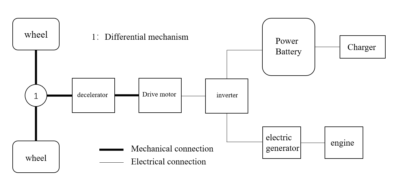
Figure 1. Structural diagram of power system for electric vehicles.
2.2. Power components
2.2.1. Drive motor. The complex operating environment of an incremental drive motor requires a small size, a wide range of speed regulation, easy control, good torque control capability, constant power output at high speed, easy maintenance, and low cost. The types of drive motors and performance comparison of electric vehicles are shown in Table 1 [2-3].
Table 1. The comparison of different typed drive motors.
Type of drive motor | Advantages | Disadvantages |
DC Motor | Mature technology, easy to control, easy to adjust the speed | Large volume, not easy to maintain |
AC induction motor | Small size, low price, easy maintenance | Low power, complex structure, not easy to control |
Switched reluctance motors | Simple structure, high starting torque, low cost | Complex control, high noise, with torque pulses |
Permanent magnet motor | High efficiency, high control, high power density and torque density, low noise | High cost and small power range |
Permanent magnet synchronous motors have high efficiency, high control accuracy, high power and torque density, and low noise, which are highly competitive in the electric drive system of electric vehicles [3]. Currently, permanent magnet synchronous motors are the mainstream choice for electric vehicles.
2.2.2. Power battery. Currently, the biggest obstacle for electric vehicles is the power battery technology, which restricts the development of trams. Table 2 shows the comparison of different batteries [4].
Table 2. The comparison between different batteries.
Function | Lead acid battery | Nickel-chromium battery | Nickel metal hydride battery | Lithium-ion battery |
Monomer voltage | 1.2-2.0 | 1.2 | 1.2-1.3 | 3.7 |
Specific energy | 30-50 | 50-65 | 75-80 | 120-140 |
energy density | 65 | 110 | 150-200 | 120-140 |
specific power | 200-300 | 170-230 | 150-400 | 190-300 |
power density | 120 | 400-600 | 430-450 | 400-500 |
cycle life | 400-600 | 800-2000 | 800-1000 | >1000 |
At present, most electric vehicles use lithium-ion batteries due to their advantages of high specific energy and specific power, excellent charge and discharge performance, long service life and low cost, etc., which make it a better choice for power batteries.
2.2.3. Range extender. For extended-range electric vehicles, the range extender only works when the power battery is low, and the engine power and economy are the primary factors. The main engines currently used in the application of extended-range electric vehicles are four-cylinder four-stroke engines, two-cylinder four-stroke engines and rotor engines. Table 3 below compares the advantages and disadvantages of the above three engines [4].
Table 3. Compares the advantages and disadvantages.
Engine | Advantage | Disadvantages |
Four-cylinder engine | Mature technology | Large volume |
Two-cylinder engine | Compact structure | Immature technology |
Rotary engine | Small size | Poor economic benefits |
At present, four-cylinder four-stroke engines are more frequently used. For example, the AITO Askworld M7, which will be launched in 2022, is equipped with a 1.5T four-cylinder range extender built specifically for range extender systems, which can achieve higher efficiency and longer range.
2.2.4. Generators. In extended-range mode, the mechanical energy output from the internal combustion engine is converted to electrical energy, part of which is stored in the drive battery and, in special cases, provides energy to the drive motor. The selection basis of generator is similar to that of drive motor. At present, most generators use permanent magnet synchronous motor.
2.3. Drive modes for add-on vehicles
Limitations due to battery technology, the driving range of electric vehicles is less than that of traditional fuel vehicles. Faced with this situation, people tend to have "mileage anxiety". Studies have shown that most people use their cars as a means of transportation within a range of 64 km, and that using an electric car within this range will reduce fuel consumption and emissions. By relying on the range extender to provide energy, the driving range of electric vehicles can be significantly increased. Therefore, the four modes of operation are summarized below:
1. Pure electric drive mode. In this mode of operation, the power battery pack directly drives the motor to make the vehicle drive, which is more suitable for urban or short-distance travel under full power. The purely electric drive mode exits when the power battery power reaches the limit value of triggering other working modes.
2. Uniform driving mode. This mode of operation, in addition to the pure electric drive mode, is the least energy-loss mode of operation. The engine power input to the motor so that the vehicle forward, not charge the battery. It is an ideal working mode, suitable for driving conditions at a constant speed.
3. Rapid acceleration driving mode. The scenario of rapid acceleration driving mode is rapid acceleration. The engine starts, and the drive motor by the power battery and generator double power supply to achieve the maximum power of the front and rear drive motor. This mode consumes more power, and only in the state of rapid acceleration can trigger the work mode work.
4. Uniform charge mode. In this mode of operation, the engine drives the generator to generate electricity through mechanical connection, and the generator transmits electric energy to the power battery. On the other hand, the power output to the motor participates in wheel charging. In this mode of operation, the power battery is in a rechargeable state so that the battery is restored to a more desirable power, and it is also the most common mode of operation [5].
3. Performance analysis of add-on vehicles
Table 4 shows the key design parameters of the EV, and Table 5 shows the performance requirements of the EV.
Table 4. Key design parameters.
Design parameters | Parameter value |
curb weight | 1700 |
Maximum design mass | 2100 |
Rolling resistance coefficient | 0.015 |
Tyre rolling radius | 0.334 |
Driveline efficiency | 0.95 |
Final drive ratio | 6.05 |
Windward area | 1.97 |
Air drag coefficient | 0.32 |
Table 5. The performance requirements.
0~100 km/s Acceleration time(s) | <10 |
Maximum speed | >140 |
Maximum climbing slope | >20 |
Pure electric mileage | >50 |
Total mileage | >400 |
3.1. Drive motor parameter matching
According to external characteristics of low-speed constant torque and high-speed constant power, the parameters to be matched are: base speed \( {n_{0}} \) , maximum speed \( {n_{max}} \) , peak power \( {P_{max}} \) , rated power \( {P_{N}} \) , peak torque \( {T_{max}} \) , rated torque \( {T_{N}} \) .
Base speed \( {n_{0}} \) and maximum speed \( {n_{max}} \) , the relationships are as follows
\( {v\frac{{n_{max}}}{{i_{0}}}_{max}} \) (1)
Where \( {i_{0}} \) is the transmission coefficient ratio, taking the value of 6.4.
After determining the maximum speed of the drive motor, according to
\( {n_{0}}=\frac{{n_{max}}}{β} \) (2)
The motor base speed can be obtained. In which β is the base speed ratio, generally taken as 2~4.
Peak power \( {P_{max}} \) and rated power \( {P_{N}} \)
The peak power of the drive motor should reach the maximum power required for maximum speed, acceleration performance and hill climbing requirements.
\( {p_{1}}=\frac{1}{η}(\frac{mgf}{3600}{v\frac{{C_{D}}A}{76140}_{max}^{3}_{max}} \) (3)
\( {p_{2}}=\frac{1}{1000η}[\frac{δm}{2t}(v_{f}^{2}+v_{b}^{2})+\frac{2}{3}mgf{v_{f}}+\frac{1}{5}{P_{a}}{C_{D}}Av_{f}^{3}] \) (4)
\( {p_{3}}=\frac{{v_{a}}}{1000η}(mgsin{{a_{cos{{a_{\frac{{C_{D}}A}{76140}_{a}^{2}max}}}max}}} \) (5)
where \( {P_{1}} \) is the maximum power determined by the maximum vehicle speed, \( {v_{max}} \) is the maximum vehicle speed, \( η \) is the driveline efficiency, \( {P_{2}} \) is the maximum power required for acceleration performance, \( {v_{b}} \) is the vehicle speed corresponding to the motor base speed, and \( {p_{a}} \) is the air density; \( {P_{3}} \) is the maximum power determined by the maximum hill climb, \( {v_{a}} \) is the hill climb speed, and \( {a_{max}} \) is the maximum hill climb, \( δ \) is conversion coefficient of rotating mass, \( {v_{f}} \) is end acceleration speed.
Therefore, the peak power of the drive motor satisfies \( {P_{max}}≥max{[{P_{1}},{P_{2}},{P_{3}}]} \) , and its rated power \( {P_{N}} \) can be calculated according to the following formula.
\( {PN_{max}} \) (6)
Where, λ is the motor overload coefficient, generally taking the value of 2~3.
Peak torque \( {T_{max}} \) rated torque \( {T_{N}} \)
According to torque - power relationship
\( P=\frac{T\cdot {n_{0}}}{9550} \) (7)
By substituting the peak power and rated power of the drive motor into the above equation, the maximum torque and rated torque of the drive motor are obtained.
3.2. Power battery parameter matching
Power cells are mainly calculated based on power and energy requirements.
Power requirements
The maximum discharge power of the power battery shall be no less than the peak power of the drive:
\( {P\frac{{P_{max}}}{{{η_{mc}}_{acc}}}_{bat-max}} \) (8)
Where, \( {P_{bat\_max}} \) is the maximum battery discharge power, kW; \( {P_{acc}} \) is the vehicle accessory power, kW.
\( {P\frac{k{C_{p}}{U_{m}}}{1000}_{bat-max}} \) (9)
k is the maximum battery discharge rate, \( {h^{-1}} \) ; \( {U_{m}} \) is the DC bus voltage, V; battery capacity determined by power, Ah.
Combining (8)(9), a new equation could be
\( {C_{P}}≥\frac{1000}{k{C_{P}}}(\frac{{p_{max}}}{{{η_{mc}}_{acc}}} \) (10)
Energy requirements
The power battery should meet the vehicle’s energy requirements:
\( {E_{B}}=\frac{mgf+{C_{D}}A{v^{2}}/21.15}{3600\cdot DOD\cdot η\cdot {η_{mc}}\cdot (1-{η_{a}})}{S_{1}} \) (11)
Where, \( {E_{B}} \) is the battery energy, KW∙h; \( v \) is the constant speed, \( km/h \) ; the battery depth of discharge is DOD, %; \( {η_{mc}} \) is drive motor efficiency; \( {η_{b}} \) is the motor discharge efficiency; \( {η_{a}} \) is the car accessory energy consumption coefficient; \( {S_{1}} \) is the pure electric driving range, km.
\( {E_{B}}=\frac{{U_{m}}{C_{E}}}{1000} \) (12)
Where, \( {C_{E}} \) is the battery capacity, Ah.
Converting the above equation, a new equation would be
\( {C_{E}}≥\frac{mgf+{C_{D}}A{v^{2}}/21.15}{3.6\cdot DOD\cdot η\cdot {η_{mc}}\cdot {η_{b}}\cdot (1-{η_{a}})\cdot {U_{m}}}{S_{1}} \) (13)
Therefore, the power cell capacity C is.
\( C={min_{k=min{(}k)}}{\lbrace max{[}{C_{P}}(k),{C_{E}}(k)]\rbrace } \) (14)
3.3. Range extender parameter matching
3.3.1. Extended range engine parameters. When power is low, the extender outputs energy to meet the driving needs of electric vehicles. The maximum output power of the extender engine should satisfy:
\( {P\frac{{P_{RE}}}{{η_{gen}}}_{eng\_max}} \) (15)
Where, \( {η_{gen}} \) is the generation efficiency of the generator.
3.3.2. Generator parameters. The output power is necessary to ensure that vehicle is travelling at a certain speed and at a constant speed (Table 6).
\( {P_{RE}}=\frac{1}{3600η{η_{mc}}}(mgfv+\frac{{C_{D}}A{v^{3}}}{76140}) \) (16)
Where \( v \) is the constant speed, \( km/h \)
Table 6. The generator parameters comparing.
Parts | Engine | Alternator |
type | Four-stroke gasoline engine | Permanent magnet synchronous motor |
Rated power | 35 | 30 |
4. Control strategy research
4.1. Control strategy method
Control strategy is the focus of the development of extended range electric vehicles, and the coordination of power drive system components affects the fuel efficiency of the entire vehicle. The vehicle control strategy is divided into the following four parts [6].
(1) Constant power control strategy. The constant power control strategy is the simplest of the four. This control strategy controls the energy distribution in the powertrain according to the threshold value of the battery SOC. The constant power strategy keeps the engine operating at its highest efficiency, driving it to charge the power cell at constant power. The advantage of this control strategy is that the engine is easy to control and can maintain constant power output at low fuel consumption and high-efficiency points, effectively avoiding frequent engine starts and stops and power fluctuations. The disadvantage is that it is impossible to feedback on the situation of each component, the energy transfer chain is long, the efficiency loss is large, and the energy efficiency of the whole vehicle is low. But the constant power strategy is the simplest and most effective strategy to design and is the basis for the design of other advanced strategies [6].
(2) Power following control strategy. Power following control strategy is an energy management method which tracks the power of the engine after the booster works, which also ensures the economy of the engine and solves the disadvantage that constant power control strategy cannot provide real-time feedback to each component. Power following control strategy is a commonly used method in research. It has the ability to dynamically detect power changes and real-time feedback. Its disadvantage is that the overall thermal efficiency is poor, which cannot reflect the advantages of extended range electric vehicles [6].
(3) Fuzzy control strategy. The fuzzy control strategy is an important branch of rule-based control strategy, of which the most important part is the fuzzy controller. A fuzzy controller's basic structure comprises a knowledge base, a fuzzy inference mechanism, a fuzzification interface and a defuzzification interface. The control mechanism of the fuzzy controller is to obtain the data value through computer sampling and then compare it with the fixed value to obtain the error signal; input the error signal as the input quantity of the fuzzy control to the fuzzification port to get the fuzzy quantity of the input quantity, which the corresponding fuzzy language can represent; thus get a subset of the fuzzy language set, and then the subset and the fuzzy relationship according to the inferred synthesis. This fuzzy control quantity is then defuzzified to obtain an accurate digital quantity, which is converted into an accurate analog quantity by digital-to-analog conversion and sent to the actuator to control the controlled object once. After sampling, repeat the above steps to complete the second control so that the control of the controlled object can be continued in a cycle. A fuzzy control strategy has good control accuracy and wide application prospects, but in engineering practice, due to limited computing power, it is difficult to achieve better control, The use of control law is relatively fixed, which makes the dynamic characteristics of the system worse and hinders the application of the fuzzy control strategy.
(4) Neural network control strategy. Neural network control, i.e., neural network control or abbreviated as neural control refers to the use of neural network as a tool for difficult to accurately describe or optimize calculation or for modelling complex non-linear objects, or fault diagnosis, etc., i.e., at the same time, some of the above functions of the adaptive combination, such systems are collectively referred to as neural network control systems, and such The control method is called neural network control. Neural network control method has strong learning ability, similar to human brain in information processing, good adaptive ability and good approximation ability of non-linear function. However, the neural network control strategy also has certain limitations. The neural network cannot intuitively give the relationship between input/output, there is uncertainty in the case of extrapolation, in the actual engineering use cannot fully exploit its advantages, subject to the role of various conditions of limitations [7].
4.2. Optimization of control strategies
In the development of extended-range electric vehicles, it has been the focus of research and development to coordinate the energy supply of power batteries and extenders and to control the extenders to meet the minimum fuel consumption and emission requirements. Because of the disadvantages of the above control strategies, the control strategies need to be optimized.
H.W. Liu [6] proposed an adaptive braking feedback control strategy, which was designed and implemented through a fuzzy control module for real-time adjustment of the regenerative braking control strategy, and the effectiveness of the control strategy proposed in the literature for improving the comprehensive regenerative braking performance of vehicles. Qinyang Lu et al. [8]. Based on the improved dynamic programming algorithm, an extended program optimization control strategy for fuel cell vehicle economy and durability was established. It sets the start-stop state of the fuel cell as a state variable and idle speed as a transition stage between start-up and shutdown of the fuel cell. The joint optimized control strategy of economy and durability of the add-on fuel cell vehicle can achieve an economy effect close to that of the classical DP strategy and mitigate the performance degradation of the fuel cell to obtain durability better than that of the classical DP strategy [9]. Andong Yin proposes a three-working-point engine control strategy that can control the engine to adjust the range extender output power according to the vehicle power demand within the optimal efficiency zone, overcoming the drawback that the rule-based fixed-point control strategy cannot adjust the range extender output power [10]. Zeng Piao Yang validated the energy management model of an incremental electric vehicle [11]. Three energy control strategies, constant power control strategy, power following strategy, and predictive power strategy, were studied for the incremental electric vehicle by analyzing the whole vehicle control strategy, components, and operating modes. All three strategies can keep the battery charge at a stable level. The whole vehicle is driven purely by electricity, and the power battery powers all three strategies through the drive motor, so the power consumption is consistent. When entering the extended-range mode, the battery power consumption shows different trends with the vehicle demand's different power and strategy modes. Among them, the SOC variation of constant power mode is significantly larger than the other two modes, which is analyzed to be caused by the single-point operation of the engine. In the single-point operation mode, the engine working point power is set higher, and each start and stop is more urgent. Therefore, each time the impact on the entire vehicle power battery charging and discharging is greater, and the battery charge state changes more. The battery charge state fluctuation is not significant in the other two strategy modes. The overall power consumption value at the beginning of the charge state of the three modes is also not very different. When the power consumption difference is large, to use the equivalent fuel consumption method to count the whole vehicle's fuel consumption.
5. Conclusion
With all the advantages of energy saving, environmental protection, economy and excellent performance of pure electric vehicles while overcoming the shortcomings of pure electric vehicles with insufficient battery storage capacity and unsatisfactory driving range, incremental electric vehicles will have a broad market prospect. The improvement of the economic performance and overall vehicle efficiency of the add-on electric vehicle relies on more in-depth research on the drive system components. In future research work, the following problems should be paid special attention to
(1)Energy conversion efficiency is further improved. In the incremental mode of operation, the energy conversion efficiency cannot yet reach the level of mechanically coupled hybrid models, and there is still much room for improvement.
(2) The control strategy is further improved. At present, the research on control strategy is still not mature enough, it is necessary to explore on the control strategy more deeply, compare the advantages and disadvantages of different optimization methods, and arrive at the best choice by comprehensive consideration.
(3) In the actual development of the incremental electric vehicle, the modelling and simulation of the whole vehicle and the control strategy are ultimately theoretical and lack convincing power. The subsequent research should build a hardware-in-the-loop simulation platform on the one hand and conduct real-world vehicle testing, on the other hand, to fully verify the correctness and feasibility of the system component selection, parameter matching, and the designed control strategy.
References
[1]. Yao X S. 2020. Energy consumption analysis of power system of an incremental electric vehicle. World of Electronic Products, 27(03):82-84.
[2]. Zhang B, Zhao J B. 2016. Summary of Research on Key Technologies of Programmed Electric Vehicle Drive System. Journal of Jiangsu Institute of Technology, 22(02),31-36
[3]. Pu W H, Liu J L. 2012. Simulation Research on Weak Field Control of Permanent Magnet Synchronous Motor for Extended Program Electric Vehicle. Micromotor, 03(03)30-31.
[4]. Zhang S K. 2019. Research on Parameter Matching and Energy Management Strategy of Programmed Vehicle Based on Small Engine. Qinghuangdao. Yanshan University
[5]. Lou Y T, Jiang C N, Liang W Q, Ling X W. 2014. A new enhanced electric vehicle drive system Hua. Journal of South China University of Technology. 42(09).107-113
[6]. Wang Y M. 2021 Parameter matching and performance simulation of power system of SUV extended electric vehicle. Jilin. Jilin University
[7]. Liu H W, Lei Y L, Fu X, Li X Z. 2021. Adaptive Brake Feedback Control Strategy for EPV Based on Multi-objective Optimization. Journal of South China University of Technology, 49(07).42-45
[8]. Lv Q Y, Teng T, Zhang B D, Zhang X, Xue Q C. 2021. Optimized control strategy for economy and durability of extended fuel cell vehicles. Journal of Harbin University of Technology. 53(07).126-133
[9]. Global automotive production will reach US$2033 billion in 2017. Intelligent Research Consulting. Industrial Information Network (chyxx.com)
[10]. Yin A D, Dong X Y, Zhang B Z, Jiang H. 2015. Multi-objective optimization of control parameters for EPV based on Isight. Journal of Hefei University of Technology. 38(03).289-294
[11]. Zeng P Y. 2019. Research on energy management strategy of incremental electric vehicle. Chongqing. Chongqing University of Technology
Cite this article
Meng,Y. (2023). Powertrain structure analysis of extended range electric vehicles. Applied and Computational Engineering,28,7-15.
Data availability
The datasets used and/or analyzed during the current study will be available from the authors upon reasonable request.
Disclaimer/Publisher's Note
The statements, opinions and data contained in all publications are solely those of the individual author(s) and contributor(s) and not of EWA Publishing and/or the editor(s). EWA Publishing and/or the editor(s) disclaim responsibility for any injury to people or property resulting from any ideas, methods, instructions or products referred to in the content.
About volume
Volume title: Proceedings of the 2023 International Conference on Mechatronics and Smart Systems
© 2024 by the author(s). Licensee EWA Publishing, Oxford, UK. This article is an open access article distributed under the terms and
conditions of the Creative Commons Attribution (CC BY) license. Authors who
publish this series agree to the following terms:
1. Authors retain copyright and grant the series right of first publication with the work simultaneously licensed under a Creative Commons
Attribution License that allows others to share the work with an acknowledgment of the work's authorship and initial publication in this
series.
2. Authors are able to enter into separate, additional contractual arrangements for the non-exclusive distribution of the series's published
version of the work (e.g., post it to an institutional repository or publish it in a book), with an acknowledgment of its initial
publication in this series.
3. Authors are permitted and encouraged to post their work online (e.g., in institutional repositories or on their website) prior to and
during the submission process, as it can lead to productive exchanges, as well as earlier and greater citation of published work (See
Open access policy for details).
References
[1]. Yao X S. 2020. Energy consumption analysis of power system of an incremental electric vehicle. World of Electronic Products, 27(03):82-84.
[2]. Zhang B, Zhao J B. 2016. Summary of Research on Key Technologies of Programmed Electric Vehicle Drive System. Journal of Jiangsu Institute of Technology, 22(02),31-36
[3]. Pu W H, Liu J L. 2012. Simulation Research on Weak Field Control of Permanent Magnet Synchronous Motor for Extended Program Electric Vehicle. Micromotor, 03(03)30-31.
[4]. Zhang S K. 2019. Research on Parameter Matching and Energy Management Strategy of Programmed Vehicle Based on Small Engine. Qinghuangdao. Yanshan University
[5]. Lou Y T, Jiang C N, Liang W Q, Ling X W. 2014. A new enhanced electric vehicle drive system Hua. Journal of South China University of Technology. 42(09).107-113
[6]. Wang Y M. 2021 Parameter matching and performance simulation of power system of SUV extended electric vehicle. Jilin. Jilin University
[7]. Liu H W, Lei Y L, Fu X, Li X Z. 2021. Adaptive Brake Feedback Control Strategy for EPV Based on Multi-objective Optimization. Journal of South China University of Technology, 49(07).42-45
[8]. Lv Q Y, Teng T, Zhang B D, Zhang X, Xue Q C. 2021. Optimized control strategy for economy and durability of extended fuel cell vehicles. Journal of Harbin University of Technology. 53(07).126-133
[9]. Global automotive production will reach US$2033 billion in 2017. Intelligent Research Consulting. Industrial Information Network (chyxx.com)
[10]. Yin A D, Dong X Y, Zhang B Z, Jiang H. 2015. Multi-objective optimization of control parameters for EPV based on Isight. Journal of Hefei University of Technology. 38(03).289-294
[11]. Zeng P Y. 2019. Research on energy management strategy of incremental electric vehicle. Chongqing. Chongqing University of Technology