


1. Introduction
FSAE is a car design and manufacturing competition sponsored by colleges and universities. Since its inception in 1981, the competition has spread to Europe, Asia, South America and Oceania from USA [1]. As a globally influential automotive design and manufacturing competition for college students. It requires the teams to design and build a single-seat mini car within one year in accordance with the rules and racing standards and complete the race.
Under the strict limit of the rules on engine power, the study of body aerodynamics is an important measure to improve the performance, which can greatly improve the stability and controllability of racing cars.Additional kits can be added, which adjust the aerodynamic performance to complete the acceleration part at low resistance, mid-to-high pressure for cross-country and endurance races, and maximum pressure down to accommodate the slide and any wet weather[1]. The aerodynamics kit is mainly composed of four parts: front wing, side box, diffuser and tail wing. The front wing, tail wing and diffuser can significantly increase the negative lift of the car, and the negative lift will act on the wheels. As a result, the wheels can get better grips. In addition, the front wing, side box and diffuser can guide the air flow, which will have a great influence on the rear wheel system, engine cooling system, etc[2].
In this article, the influence of designing parameters of aerodynamic kits and the whole body on the negative lift and air resistance is explored. Also, 3D components is established and the aerodynamic analysis is performed. Through multiple simulations using ANSYS, the car body shape and aerodynamic kits is optimized by using streamline diagrams, pressure cloud maps, and velocity vector maps obtained from simulations. The results show that the body and aerodynamics kits design can significantly improve the speed and driving stability of the car. This article may offer a reference for the design optimization of racing cars.
2. Design objectives and relevant constraints
2.1. Design objectives
1) In the appearance design, based on the streamline diagrams,designing a smooth and full shaped body cover, in order to achieve good surface quality, beautiful coating, high value of the vehicle ornamental effect [3].
2) Improving the integration ability of the nose cone on air, so that the aerodynamic kits gain better performance.
3) Each component has been designed with care to provide significant down force and maintain a reasonable lift-to-drag ratio.
4) Reducing the aerodynamic sensitivity of the vehicle and coinciding the wind pressure center with the mass center of the vehicle [4].
2.2. Relevant constraints
For safety considerations and to establish unified competition standards, strict regulations have been implemented for various parameters of race cars in the competition. These parameters include the engine system, electrical system, transmission system, braking system, suspension system, steering system, car body and aerodynamic kits. For car body and aerodynamic kits, certain components such as spoilers and diffusers are allowed, but their size and configuration are strictly regulated to prevent excessive down force and drag.The detailed rules are as follows.
2.3. Front wing related rules
The front wing cannot extend beyond 700 mm (27.6 inches) in front of the front tires.
The front wing cannot be wider than the outer edges of the front tires (measured at the height of the front wheel centers).
When the driver is in the car, the minimum static ground clearance of any part of the car, except for the tires, cannot be less than 30 mm.
From a front view, any part of the front wheels/tires assemblies that is higher than 250 mm (9.8 inches) above the ground cannot be covered by any aerodynamic device (when there is no driver in the car).
The horizontal edges of all front wings (including wing lets, end plates, Gurney flaps, and the bottom plates) that face forward and may come into contact with pedestrians must have a minimum rounded corner radius of 5 mm (0.2 inches), and the vertical edges must have a minimum rounded corner radius of 3 mm (0.12 inches).
The front wing cannot be wider than the outer edges of the front tires (measured at the height of the front wheel centers), and it must not be more than 250 mm above the ground at the front of the wheels [5].
2.4. Diffuser related rules
From a top view, the aerodynamic device (such as the bottom plates) can extend outward to a line that is located at the height of the tires centers and connects the outer surfaces of the front and rear tires, between the center lines of the front and rear wheel axles.
When there is no driver in the car, any aerodynamic device or other part of the car located between two vertical cross-sections that intersect the center lines of the front and rear wheels cannot be more than 500 mm (19.7 inches) above the ground. (For a car moving from front to back, the body within the vertical plane 400 mm away from the center line on each side is not subject to these requirements) [5].
2.5. Rear wing related rules
The rear wing cannot extend beyond 250 mm (9.8 inches) behind the rear tires.
The rear wing cannot be wider than the inner edges of the rear tires (measured at the height of the rear wheel centers).
When measured with no driver in the car from a side view, no part of the rear wing or aerodynamic device (including the end plates) can be higher than 1.2 m above the ground. The horizontal edges of all rear wings (including wing lets, end plates, Gurney flaps, and the bottom plates) that face forward and may come into contact with pedestrians must have a minimum rounded corner radius of 5 mm (0.2 inches), and the vertical edges must have a minimum rounded corner radius of 3 mm (0.12 inches) [5].
3. Design and optimization car body and aerodynamic kits
The design objects include the body shape, side pods, front wing, diffusers and rear wing, which will be introduced in the order from the front to the back of the racing car in the following text.
3.1. Design of body shape
Due to considerations of aesthetic and smooth surface transitions, the initial version of the car body model created through CATIA has a low profile, with the nose tip lowered and a small gap between the front wings, resulting in an overall longer length. As shown in Figure 1, after analyzing the external flow field of the entire vehicle, the following issues are found:
1) the excessive length of the car body leads to a large turning radius, affecting the flexibility and handling of the race car, with increased air resistance.
2) the low position of the nose cone results in excessive lift at high speeds, reducing tire grip and affecting the stability and safety of the vehicle.
3) the small gap between the car body and front wing creates significant resistance to airflow, which becomes complex and unstable after passing through the front wing, increasing the risk of stalling and negatively impacting the stability of the race car.
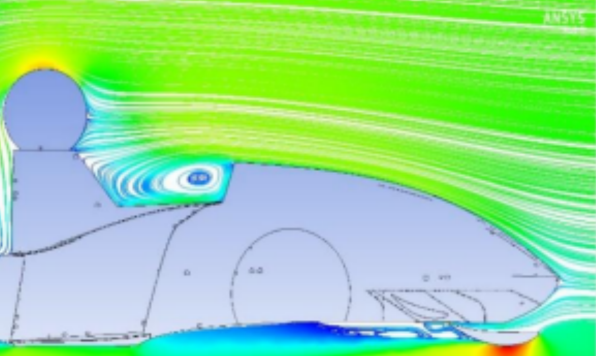
Figure 1. Flow diagram of the original nose cone.
To address the aforementioned issues, the nose cone is raised,the ground clearance of the car body is slightly increased,and the length of body is shortened appropriately.The front wing of the car has been engineered with a slight curvature, a small attack angle, and an enlarged gap between the wing and body to facilitate the organization of airflow. In addition, the flap height has been reduced to increase distance between the body and flaps, which results in directing more air towards the side pods [6].
Through simulations by ANSYS,the car body shape is optimized using streamline diagrams, pressure cloud maps and velocity vector maps obtained from simulations. Additionally,the aerodynamics kits is designed to work in conjunction with the car body to achieve the goal of increasing down force and reducing air drag.The main aspects of optimization include:
1) smoothing out the car body curves to make them more streamlined.
2) establishing a smoother surface to eliminate local resistance on the car body's sides.
3) improving severe airflow separation at the bottom of the car body by reducing its inclination and increasing its flatness.
4) adjusting the inclination angle, height, and width of the car body to achieve optimal aerodynamic performance.
After optimization,another external flow field analysis on the entire vehicle is conducted, as shown in Figure 2.
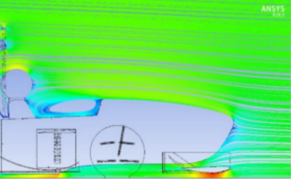
Figure 2. Flow diagram of the optimized nose cone.
The analysis reveals that the turbulent flow is transformed into a cleaner and neater airflow, reducing the risk of stalling. The airflow is guided by the subsequent car body towards the side pods and diffuser, improving their working conditions and providing sufficient heat dissipation for the water tank in conjunction with the side pods [7].
The final 3D model is shown in Figure 3. The surfaces is constructed with continuous curvature changes and smoothly connected various modules to reduce the separation of boundary layer airflow on the car body surface and improve the quality of the surface flow field.
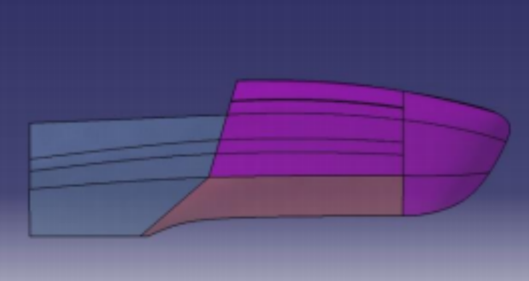
Figure 3. Side view of the body cover parts.
3.2. Design of side pods
Considering the engine cooling issue,optimizing the side pods cooling performance is focused on. Since the lack of experimental conditions,a relatively reliable solution is chosen.The upper surface is designed as a wing shape to reduce the upwash of airflow, and the lower surface is designed as a flat to optimize the flow field. At the wingtip of the side pods, high-speed airflow will form vortices between the upper and lower surfaces, leading to energy loss and increased resistance. Reducing the upwash can decrease the strength of these vortices and thus lower the resistance at the wingtip. Upwash can also cause uneven pressure distribution on the wing surface, resulting in a large pressure gradient and reducing the lift coefficient and aerodynamic efficiency. Reducing the upwash of airflow can improve the pressure distribution on the wing surface. Additionally, using a flat design for the lower surface can reduce air drag, making the airflow smoother, reducing turbulence, and providing more airflow for the engine's radiators.
By simplifying the structure through fusion design with the diffuser,the side pods are arranged in a position opposite to the inner sides of the front wheels to obtain more airflow for cooling.A low profile is also used to enable the driver to enter and exit the cockpit more conveniently. The structure of side pods is shown in Figure 4.
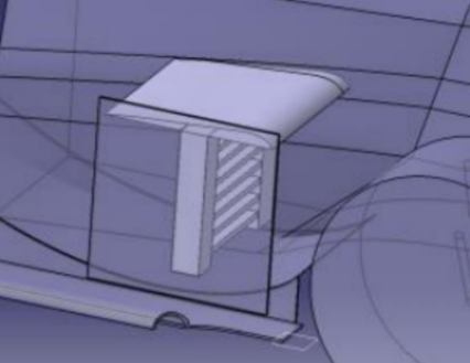
Figure 4. Relative position of side pod, diffuser and radiator
3.3. Design of front wing
The front wing is a crucial aerodynamic component that is primarily used to generate down force to enhance the stability and handling performance of a vehicle during high-speed travel. By adjusting parameters such as shape and angle of the front wing, the generated down force can be precisely controlled, and the vehicle's performance can be optimized at different speeds. Additionally, the front wing can also play a role in reducing aerodynamic drag force by redirecting airflow and avoiding the production of resistance from the front of the vehicle. Through the design of the front wing, various aspects such as wing profile selection, determination of main wing parameters, and design of combination wing parameters are considered.
3.3.1. Wing profile selection. The principles of selection include the following four points:
1) Suitable for low-speed driving conditions of the race car (using low-speed wing profiles).
2) Ensure appropriate negative lift and lift-to-drag ratio.
3) Small curvature to reduce the upwash of airflow.
4) Stable performance under different working conditions (good anti-pitching ability) [8].
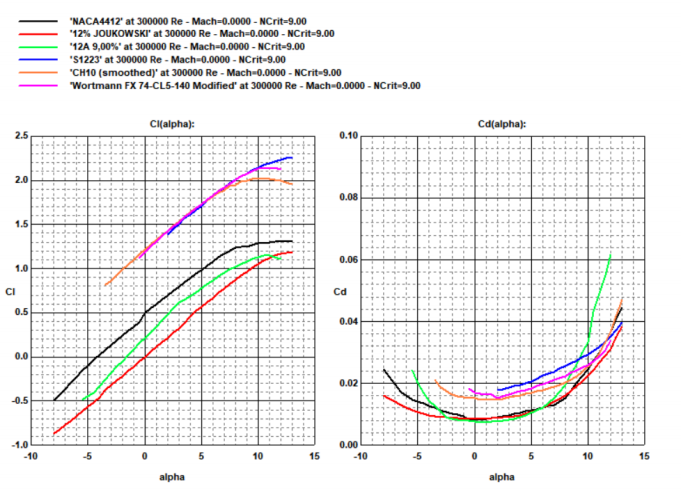
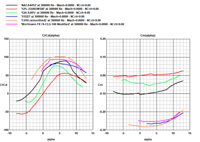
Figure 5 shows a comparison of the lift coefficient, drag coefficient, lift-to-drag ratio, and pitching moment coefficient for several airfoil shapes selected from the airfoil database. Through comparative analysis of the lift coefficient and drag coefficient of different wing profiles at different angles of attack in the PROFILI wing profile library. Based on the analysis, the NACA4412 flat wing profile exhibits the same amount of negative lift as other wing profiles in the angle of attack range of -4°~9°, while it achieves a maximum lift-to-drag ratio.The S1223 wing profile has the highest lift coefficient and the lowest drag coefficient after the angle of attack increases to 12°, resulting in the highest lift-to-drag ratio.The NACA4412 is chosen as the main wing profile for the front wing and the S1223 is chosen as the flap wing profile. The cross-sections of the two wing profiles are shown in the Figure 6.
|
|
Lift coefficient Cl | Drag coefficient Cd |
|
|
Lift-to-drag ratio Cl/Cd | Pitching moment coefficient Cm |
Figure 5. Plot of aerodynamics coefficient | |


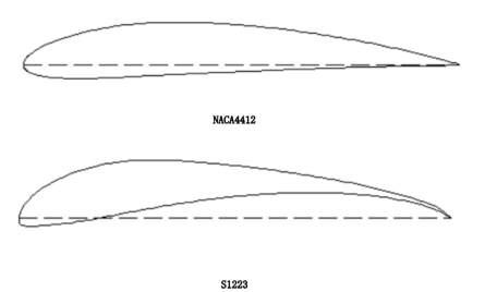
NACA4412

S1223
Figure 6. Cross sections of two airfoil types.
3.3.2. Parameters of the main wing. Front Wing Total Width: The estimated total width of the front wing is 1400 mm (the distance from the outsides of the race car tires is about 1416 mm), and the main wing width is determined as 1260 mm, leaving space for the design of the end plates.
Chord length of the Main Wing: Due to related restrictions, the main wing is the main source of negative lift provided by the front wing. Generally, the longer the chord length of the main wing, the greater the negative lift generated by the front wing. Therefore,a design with a main wing chord length of 400 mm is chosen.
Chord length of Flap Wing: The presence of the flap wings will inevitably reduce the amount of air intake for the side pods, as they will guide the airflow above the side pods, preventing air from directly entering the interior of the side pods. Considering the chosen longer chord length of the main wing and the need to meet regulatory requirements and the air intake needs of the side pods,using a flap wing with a chord length of 150 mm is decided.
Width of End plates: An outward-expanding end plates with a gentle curvature is designed to guide the airflow at the front wing's edge outwards, separated from the tires to reduce air resistance around the tires. The width of the end plates is selected as 70 mm. The CATIA model of the front wing end plates is shown in Figure 7.
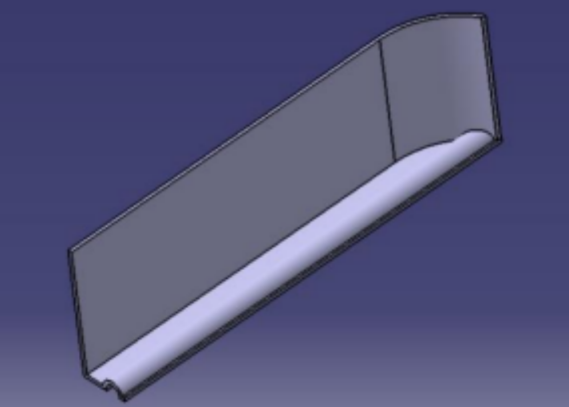
Figure 7. Design of the front wing end plates.
3.3.3. Parameters of combined Wing. The front and flap wings of the race car make great contribution to increasing overall negative lift, reducing drag, and improving stall characteristics [6,7]. In designing individual components, their impact on the entire vehicle should be considered. Therefore,a gap of 250 mm between the flap wing and the body is set to increase the airflow to the side pods and meet the engine heat dissipation requirements.As shown in Figure 8, the airflow rate at the front cross-section of the radiator inlet is calculated to be 0.31 kg/s using the ANSYS Fluent module for analysis.
Based on a series of simulation calculations, the objectives include the effects of four variables, namely main wing angle of attack, flap wing angle of attack, front wing seam, and front wing distance from the ground, on the performance of the front wing.The results are shown in Table 1.The best group is obtained when the main wing attack Angle is 0°,the flap attack angle is 35°, the seam path is 20 mm (5% of the main wing chord length), and the ground clearance is 60 mm. At 54 km/h, negative lift force is 47N, the drag force is 7N.
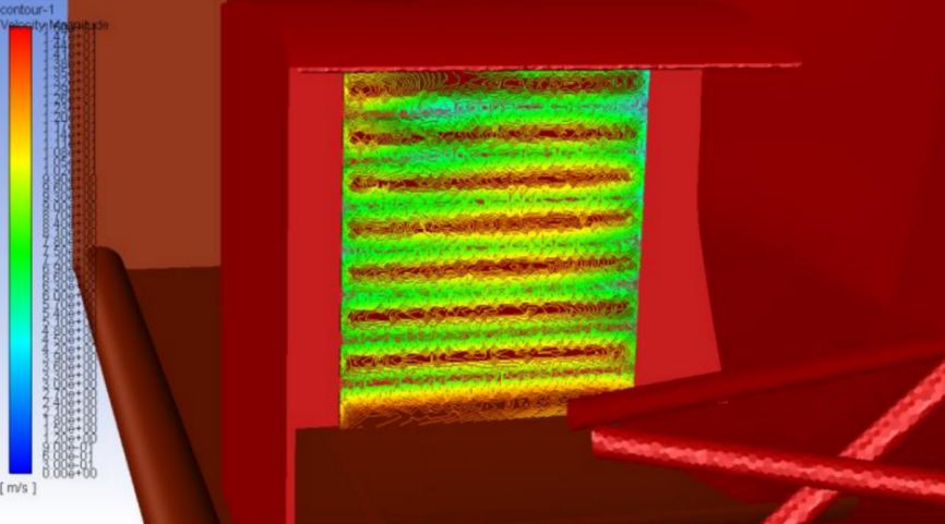
Figure 8. Calculation of the air flow of the front air inlet section of the radiator.
Table 1. Comparison of the combined wing analysis data.
Attack angle/° | Distance from the ground/mm | Negative lift force/N | Drag force/N |
35 | 55 | 45.18 | 7.0±0.5 |
35 | 60 | 47.09 | 7.0±0.5 |
35 | 65 | 44.59 | 7.0±0.5 |
40 | 55 | 40.72 | 7.0±0.5 |
40 | 60 | 41.68 | 7.0±0.5 |
40 | 65 | 37.66 | 7.0±0.5 |
Optimization of flaps:
Taking into account the significant loss in aerodynamic performance resulting from the design of flaps with large clearance, the tests are conducted to examine the aerodynamic effects and side pods intake efficiency of extra flaps with increased width and angle of attack towards the wing on the existing design. The data is shown in Table 2. In lateral comparison, it is found that when a S1223 wing with a width of 150 mm and an attack Angle of 15° is added, the front wing produced a negative lift force of 61N at 54 km/h, and the resistance decreased to 6.3N. At this time, the gas flow of the cross section of the side pods only decrease to 0.49kg/s, and the comprehensive improvement is significant.Thus,the final flap structure design is determined.
Exploration of twin main wings:
Several problems arise in the design of the front wing of a single main wing:the pitch sensitivity of the single main wing is high,single main wing is easy to stall,interfere with the car body during the installation process and the volume of air intake of side pods is low.
A tentative solution of the front wing is considered,which uses twin main wings.Using NACA5409 airfoil with a chord length of 200 mm for two wing sections, the new design concepts and research areas in the field are explored.
In the later analysis,it is found that the twin main wings can solve several kinds of problems in the single main wing above[9]. Only because the familiarity of the twin main wings is still not high,and the whole is in the groping stage.Considering that the installation of the twin main wings lacks of experience and the current design of the twin main wings has a loss of negative lift to the front wing,therefore the design of the single main wing is used. Through the optimization of flaps and other components above,the problems can be solved. The CATIA model in Figure 9 is the front wing of twin main wings.
Table 2. Comparison of the flap optimization data.
Category | Negative lift force/N | Drag force/N | Radiator flow/(kg/s) |
Preliminary determination of front wing | 47 | 7 | 0.51 |
Flaps are increased by a width of 50 mm | 52 | 7.2 | 0.48 |
Flaps are increased by a width of 100 mm | 57 | 7.5 | 0.46 |
Flaps width increase to 150 mm, attack angle 15° | 61 | 6.3 | 0.49 |
Flaps width increase to 150 mm, attack angle 20° | 57 | 6.5 | 0.46 |
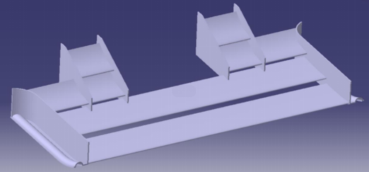
Figure 9. Model of the twin main wings.
3.4. Design of diffuser
3.4.1. Working principle of the diffuser. The diffuser is essentially a form of Venturi tube. Air passes through the diffuser from the bottom of the vehicle and is directed upward by inclined blades, creating a low-pressure area. The pressure inside the diffuser gradually returns to normal pressure. The pressure difference between the upper and lower surfaces of the diffuser generates a certain negative lift. At the same time, the high-speed airflow below the diffuser is also guided to the low-speed airflow area, making the airflow smoother and reducing turbulence around the race car.
3.4.2. Design of diffuser style and profile. The tail diffuser may interfere with other parts of the race car, so a side-mounted form is chosen. From a frontal perspective, the diffuser is positioned on the interior side of the rear wheels, at a minimum distance of 75 mm away from the tires.
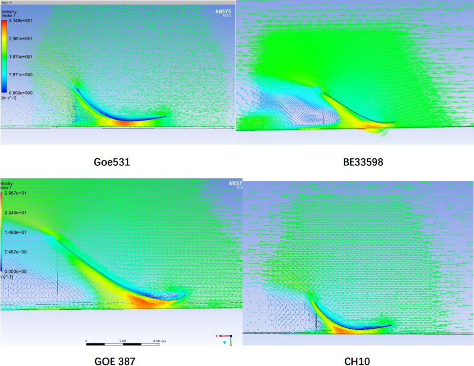
The internal structure of the diffuser should allow for rapid airflow and make it adhere closely to the lower surface, minimizing the risk of flow separation while generating high down force and low air drag. Through repeated analyses of individual components by changing the length, height and angle of attack of the wing profile, and screening based on the above standards, it is found that the BE33598 and GOE387 wing profiles have severe stall problems, and the GOE531 wing profile have poor airflow adherence. The CH10 wing profile has the advantages of guiding airflow adherence and being less prone to stall, so the CH10 wing profile is chosen for the diffuser. As shown in Figure 10, the results of four different airfoil simulations are presented individually.
|
|
GOE531 | BE33598 |
|
|
GOE387 | CH10 |
Figure 10. Simulation results of airfoils. | |


3.4.3. Other parameters of the diffuser. After installing the diffuser into the vehicle, only the rotation angle of CH10 and the distance between the curve valley and the bottom plate of the diffuser need to be considered as variables. By conducting fluid analyses under the same conditions, the data is obtained as shown in Table 3 and Table 4. The final ground clearance for the diffuser is determined to be 50 mm, with a rotation angle of 12°.
3.4.4. Layout of the diffuser. Placing the side-mounted diffuser in front of the rear wheels effectively avoids the separation zone at the rear. In the initial diffuser layout plan, the diffuser is mostly located in the turbulent flow area behind the rear wheels. The large amount of uncertain airflow causes a sudden decrease in the negative pressure of the diffuser, and the excessive upwash caused by the front wing also prevents the diffuser from functioning properly. The peak negative pressure of the bottom plate decreases from around -300Pa to around -120Pa.
After the improvement, a front wing with a low angle of attack and small curvature is used, and the diffuser is placed as close as possible to the inside to enhance the induction of the airflow to the rear wing. The negative pressure of the diffuser increases by about 90%, while the drag force remains almost unchanged.
Table 3. Comparison of lift and drag at different rotation angles.
Angle of rotation /° | Negative lift force/N | Drag force/N | Lift drag ratio |
10 | -28 | 17 | 1.65 |
12 | -37 | 18 | 2.06 |
14 | -30 | 18 | 1.61 |
16 | -26 | 21 | 1.24 |
18 | -28 | 19 | 1.52 |
20 | -25 | 20 | 1.25 |
(Curve ground clearance 55 mm).
Table 4. Comparison of lift and drag at different ground clearances.
(Rotation angle 15°).
Ground clearances | Negative lift force/N | Drag force/N | Lift drag ratio |
50 mm | -37 | 17 | 2.18 |
55 mm | -30 | 18 | 1.67 |
60 mm | -22 | 18 | 1.22 |
65 mm | -20 | 18 | 1.11 |
3.5. Rear wing design
3.5.1. Selection of wing parameters. Angle of attack: The initial version of the wing has a small angle of attack for the flaps, resulting in lower air resistance and less down force. The setting of the flap angle of attack is actually a trade-off between the tyre grip and the maximum speed. Considering that the average speed in the endurance race of the Formula Student China competition is generally between 50 km/h and 80 km/h,to increase the flap angle of attack is decided. The angle of attack for the first flap increases from 25° to 36°, and the angle of attack for the second flap increases from 45° to 65°, resulting in an increase of 9N (from 77 to 86) in down force half-model[10].
Genie Flap: The impact of various lengths of Gurney flaps on the performance of the rear wing is analyzed, and the results are presented in Table 5. Referring to the lap speed simulation results, the influence of the change of drag on lap speed is much less than that of pressure on lap speed[11]. Therefore,finally to use the 32 mm Gurney flap is decided.Although the lift drag ratio decreased, it is still very helpful to improve the lap speed.
Table 5. Effects of the length of the Gurney flap on the rear wing.
Length of the Gurney flap | Negative lift force/N | Drag force/N |
0 mm | 172 | 68 |
24 mm | 186 | 80 |
32 mm | 191 | 88 |
Beam wings: Following the method mentioned in the previous section, two schemes are proposed for beam-wing design, and the results of the analysis are shown in Table 6. The decision to install a wing with the S1223 airfoil, a chord length of 150 mm, and equipped with a 10 mm-long Gurney flap is made.
Table 6. Effects of the beam wing on the whole rear wing.
Beam wing | Negative lift force/N | Drag force/N |
No | 160 | 33 |
Yes | 170 | 34 |
End plates design: The common design is using large end plates to improve the pressure-keeping effect of the end plates. However, in the vehicle analysis, it is found that the impact of cutting off part of the end plates on the down force can be ignored.The down force after cutting the end plates drops from 96N to 95N. The design of the small end plates reduces the weight on the one hand, and on the other hand reduces the air drag under the side wind condition [12]. The following is a side view of two types of end plates, as shown in Figure 11.
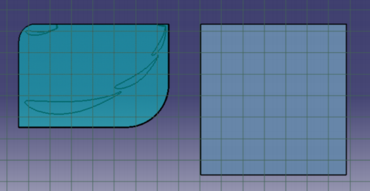
Figure 11. Design of the two end plates.
4. Result
In this paper, the structures of major aerodynamic components of the car body is designed. For the design of the front wing, the calculation fluid dynamics(CFD) simulation results show that the optimal performance of the composite wing can be obtained if the main wing attack angle is set as 0°, the flap attack angle is set as 35° and the slot is set as 20 mm (5% length of the main wing chord). The ground clearance should be set as 60 mm. On this basis, if a S1223 blade with a width of 150 mm and an angle of attack of 15° is added to the flap design, the increase of air flow is more significant. The width of the end plate should be 70 mm. And the front wing retains the single main wing design.
In terms of the design of the body shape, the nose cone of the car is raised, the body clearance is slightly increased, and the body length is shortened appropriately. The front wing is designed with small curvature and small angle of attack while its gap with the body is reduced. Meanwhile the flap height is reduced and the distance between flap and the car body is increased. Thereby the airflow is organized, and more air is directed to the side pods. After the optimization, the turbulence is transformed into a cleaner and more orderly airflow, and the risk of stalling is well reduced. The subsequent vehicle body directs the air flow to the side pod and diffuser to improve performance. The side pod provides enough heat dissipation for the tank.
The CH10 side diffuser is selected for analysis. Rotation angle and ground clearance are two important indexes. When the ground clearance is 55 mm and the rotation angle is 12°, the maximum lift-drag ratio of 2.06 is obtained.
In terms of tail fin design, it is assumed that Gurney flaps and beam fins are installed in the tail fin respectively. Through simulation, the influence of Gurney flaps and beam fins on down force and drag is explored. The installation of Gurney flaps and beam fins is beneficial to further improve the aerodynamic performance of the car.
After the design is completed, the simulation is carried out under the working condition of 15 m/s, and the vehicle data is shown in Table 7. Figure 12 is a pressure distribution map obtained from a vehicle analysis. The aerodynamic characteristics of the whole vehicle are eximious. And the design objectives are satisfied.
Table 7. Lift drag ratio provided by different parts.
Parts | Negative lift force/N | Drag force/N | Lift drag ratio |
Body shape | 2.0 | 30.0 | 0.07 |
Front wing | -122.0 | 12.6 | -9.68 |
Diffuser | -192.0 | 96.0 | -2.00 |
Rear wing | -65.0 | 26.0 | -2.50 |
Whole vehicle | -377.0 | 164.6 | -2.29 |
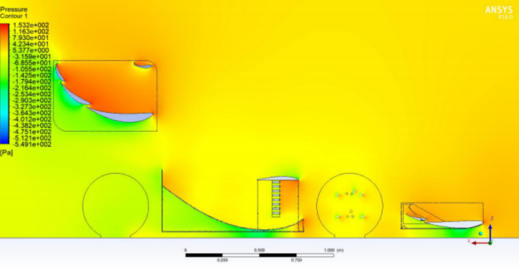
Figure 12. Pressure profile of the vehicle.
5. Conclusion
The design of the formula racing car's major aerodynamic components plays an important role in the performance of the car. In this paper, CFD simulation method is used to analyze the relevant parameters of the front wing, the diffuser, the rear wing and the body shape. Improvements to the design of the above aerodynamic components can significantly help improve the lift-drag ratio of the whole vehicle. The best design scheme is obtained. The lift of the whole vehicle is -337N while the drag is 164.6N. The lift-drag ratio has reached -2.29. The front wing and the diffuser make the biggest contribution to lift. The design objectives are well satisfied.
References
[1]. Wordley S and Saunders J 2006 SAE Tech. Pap. Aerodynamics for Formula SAE: Initial design and performance prediction 01 P0806
[2]. Hetawal S, Gophane M, Ajay B.K. and Mukkamala Y 2014 Procedia Engineering Aerodynamic Study of Formula SAE Car 97 P1198-1207
[3]. Zhuge X 2013 Research on body shape design of electric vehicle (Wuhan:Wuhan University of Technology)
[4]. Song S 2021 Joint study on Aerodynamics and Handling Stability of FSAE racing cars under unstable winds (Jilin:Jilin University)
[5]. Formula University of China Rules Committee 2020 Rules of Formula College China in 2020 (China:China Society of Automotive Engineering)
[6]. Wang S, Zhang Y and Ren H 2020 Design Design of aerodynamics kit of Formula Racing car for university students 33 P8-10
[7]. Feng H, Zhang Z, Li Y, Li Q and Niu X 2020 Proceedings of China SAE Annual Conference 2020 Optimization design of FSAE racing wing 8 P6.
[8]. Zhang Z, Song S, Wang G and Zhang Y 2022 Journal of Jilin University Aerodynamic characteristics of a racing car in pitch motion (2022)10
[9]. Wang J, Wang Y, Xia Y, Xu Z and Yan Z 2021 Proceedings of China SAE Annual Conference 2021 Optimal design of the front wing of FSAE racing car 8 P6.
[10]. Zhang Y, Li C and Pei Y 2021 Proceedings of China SAE Annual Conference 2021 CFD simulation and analysis of intelligent adjustment tail of racing car 8 P8
[11]. Yang Z, Zhang B and Jia Q 2021 Journal of Tongji University Lap speed simulation of coupled aerodynamic parameters and body attitude change 49 P124-134
[12]. Zhang Y, Yang C, Zhan D, Zhang Z and Wang D 2019 Journal of Beijing Institute of Technology Research on aerodynamic performance of Formula Car in crosswind 39 P491-6
Cite this article
Dai,Z.;Dai,Z.;Rong,Y. (2023). Design and optimization of formula racing car body and aerodynamic kits. Applied and Computational Engineering,28,119-131.
Data availability
The datasets used and/or analyzed during the current study will be available from the authors upon reasonable request.
Disclaimer/Publisher's Note
The statements, opinions and data contained in all publications are solely those of the individual author(s) and contributor(s) and not of EWA Publishing and/or the editor(s). EWA Publishing and/or the editor(s) disclaim responsibility for any injury to people or property resulting from any ideas, methods, instructions or products referred to in the content.
About volume
Volume title: Proceedings of the 2023 International Conference on Mechatronics and Smart Systems
© 2024 by the author(s). Licensee EWA Publishing, Oxford, UK. This article is an open access article distributed under the terms and
conditions of the Creative Commons Attribution (CC BY) license. Authors who
publish this series agree to the following terms:
1. Authors retain copyright and grant the series right of first publication with the work simultaneously licensed under a Creative Commons
Attribution License that allows others to share the work with an acknowledgment of the work's authorship and initial publication in this
series.
2. Authors are able to enter into separate, additional contractual arrangements for the non-exclusive distribution of the series's published
version of the work (e.g., post it to an institutional repository or publish it in a book), with an acknowledgment of its initial
publication in this series.
3. Authors are permitted and encouraged to post their work online (e.g., in institutional repositories or on their website) prior to and
during the submission process, as it can lead to productive exchanges, as well as earlier and greater citation of published work (See
Open access policy for details).
References
[1]. Wordley S and Saunders J 2006 SAE Tech. Pap. Aerodynamics for Formula SAE: Initial design and performance prediction 01 P0806
[2]. Hetawal S, Gophane M, Ajay B.K. and Mukkamala Y 2014 Procedia Engineering Aerodynamic Study of Formula SAE Car 97 P1198-1207
[3]. Zhuge X 2013 Research on body shape design of electric vehicle (Wuhan:Wuhan University of Technology)
[4]. Song S 2021 Joint study on Aerodynamics and Handling Stability of FSAE racing cars under unstable winds (Jilin:Jilin University)
[5]. Formula University of China Rules Committee 2020 Rules of Formula College China in 2020 (China:China Society of Automotive Engineering)
[6]. Wang S, Zhang Y and Ren H 2020 Design Design of aerodynamics kit of Formula Racing car for university students 33 P8-10
[7]. Feng H, Zhang Z, Li Y, Li Q and Niu X 2020 Proceedings of China SAE Annual Conference 2020 Optimization design of FSAE racing wing 8 P6.
[8]. Zhang Z, Song S, Wang G and Zhang Y 2022 Journal of Jilin University Aerodynamic characteristics of a racing car in pitch motion (2022)10
[9]. Wang J, Wang Y, Xia Y, Xu Z and Yan Z 2021 Proceedings of China SAE Annual Conference 2021 Optimal design of the front wing of FSAE racing car 8 P6.
[10]. Zhang Y, Li C and Pei Y 2021 Proceedings of China SAE Annual Conference 2021 CFD simulation and analysis of intelligent adjustment tail of racing car 8 P8
[11]. Yang Z, Zhang B and Jia Q 2021 Journal of Tongji University Lap speed simulation of coupled aerodynamic parameters and body attitude change 49 P124-134
[12]. Zhang Y, Yang C, Zhan D, Zhang Z and Wang D 2019 Journal of Beijing Institute of Technology Research on aerodynamic performance of Formula Car in crosswind 39 P491-6