


1. Introduction
In today’s society, intelligent vehicle technology has made great progress and is gradually changing the way we travel and transportation systems. With the continuous evolution of autonomous driving technology, the simulation of intelligent vehicles has become a field of concern, which provides a powerful tool for the design and performance evaluation of intelligent vehicles by simulating the behavior of vehicles in virtual environments [1]. The design and analysis of simulated intelligent vehicles is not only related to the safety, efficiency and sustainability of the transportation system, but also related to the improvement of the quality of human life and the sustainability of urban development. Therefore, this paper aims to delve into the design and analysis of simulated intelligent vehicles and explore their potential impact on the realization of autonomous driving technology and intelligent transportation systems.
With the continuous advancement of urbanization, traffic congestion, traffic accidents and environmental pollution become increasingly prominent. In this context, intelligent vehicle technology has emerged to improve the efficiency, safety and sustainability of transportation systems. As an important component of this technology field, artificial intelligent vehicles provide a safe, cost-effective and efficient way for automakers, government agencies and researchers to test and validate different intelligent transportation systems and autonomous driving algorithms [2]. By simulating various driving situations in a virtual environment, artificial intelligent cars are expected to accelerate the development of autonomous driving technology, reduce the cost of experiments, and reduce the reliance on test vehicles on real roads.
This paper will cover several key aspects of the design and analysis of simulated intelligent vehicles, including the establishment of simulation environments, the development of vehicle dynamics models, the design of perception and control systems, and the study of performance evaluation and verification methods. We will also explore the potential applications of simulated intelligent vehicles in different application areas, such as the development of autonomous vehicles, optimization of intelligent traffic management systems, and traffic flow simulation [3].
Finally, through the design and analysis of simulation intelligent vehicle in-depth research, this paper aims to Promote the development and application of intelligent vehicle technology to provide strong support for new solutions to solve the challenges facing today’s transportation system. As autonomous driving technology continues to mature and spread, we believe that artificial intelligent vehicles will play a key role in the improvement and innovation of future transportation systems [4].
2. Methods
2.1. Construction of vehicle dynamics model
\( \begin{matrix}m({v_{y}}+v_{x}\overset{˙}{φ}=C_{αf}(\frac{{\overset{˙}{φ}_{a}}+{v_{y}}}{{v_{x}}}-δ)C_{αx}(\frac{{v_{y}}-{\overset{˙}{φ}_{b}}}{{v_{x}}}) \\ I\overset{¨}{φ}=aC_{αf}(\frac{{\overset{˙}{φ}_{a}}+{v_{y}}}{{v_{x}}}-δ)bC_{αr}(\frac{{v_{y}}-{\overset{˙}{φ}_{b}}}{{v_{x}}}) \\ \end{matrix} \) (1)
In establishing the two-degree-of-freedom vehicle dynamics differential equation, m is the mass of the vehicle, 𝑣 𝑦 is the lateral movement speed, is the longitudinal 𝑣 igh direction motion speed, 𝜑 is the yaw angular acceleration of the vehicle, 𝜑𝑎 and 𝜑𝑏 represent the yaw angular velocity of the front and rear wheels respectively, a and b represent the distance from the center of mass of the car to the front and rear axles respectively, C𝛼𝑓 and C𝛼𝑟 represents the cornering stiffness of the front and rear wheels respectively (see Figure 1).
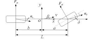
Figure 1. Two degrees of freedom vehicle model [5]
Let \( {v_{y}}=\overset{˙}{y} \) the above two-degree-of-freedom equation in the form of a state equation
\( (\begin{matrix}\overset{¨}{y} \\ \overset{¨}{φ} \\ \end{matrix})=(\begin{matrix}\frac{{C_{αf}}+{C_{af}}}{m{v_{x}}}\frac{a{C_{αf}}-b{C_{ar}}}{m{v_{x}}}-{v_{x}} \\ \frac{a{C_{αf}}-b{C_{af}}}{I{v_{x}}}\frac{{a^{2}}{C_{αf}}+{b^{2}}{C_{af}}}{I{v_{x}}} \\ \end{matrix})(\begin{matrix}\overset{˙}{y} \\ \overset{˙}{φ} \\ \end{matrix})+(\begin{matrix}-\frac{{C_{αf}}}{m} \\ -\frac{a{C_{αf}}}{I} \\ \end{matrix})δ \) \( X=(\begin{matrix}\overset{˙}{y} \\ \overset{˙}{φ} \\ \end{matrix}),u=δ \) (2)
Then the two-degree-of-freedom vehicle lateral dynamics control equation can be expressed as \( \overset{˙}{X}=AX+Bu \)
\( A=(\begin{matrix}0 & 1 & 0 & 0 \\ 0 & 0 & 0 & \frac{{C_{αf}}+{C_{αr}}}{m{v_{x}}}-\frac{{C_{αf}}+{C_{αr}}}{m}\frac{a{C_{αf}}-b{C_{αr}}}{m{v_{x}}} \\ 0 & 0 & 0 & 1 \\ 0 & 0 & 0 & \frac{a{C_{αf}}-b{C_{αr}}}{I{v_{x}}}-\frac{a{C_{αf}}-b{C_{αr}}}{I}\frac{{a^{2}}{C_{αf}}-{b^{2}}{C_{αr}}}{I{v_{x}}} \\ \end{matrix})\ \ \ (3) \)
2.2. Lateral motion analysis
During the movement of the intelligent driving vehicle, based on the road, traffic environment and other information collected by various sensors installed on the vehicle body, the collected data will be sent to the control system through information fusion, and judged by the control system’s logic algorithm. Finally, reasonable signals are sent to each actuator of the vehicle to complete vehicle motion control. Lateral motion analysis assumes that the planned path parameters are known to be (𝑟, 𝑦𝑟, 𝑣𝑟, 𝜃𝑟, 𝑎𝑟). The intelligent driving vehicle controller receives the data from the path planning system and will reduce the deviation between the vehicle’s actual movement path and the expected path by controlling and adjusting the vehicle’s movement speed and steering wheel angle. Analyzing the vehicle motion shows that after receiving the planned path, there will be longitudinal errors, lateral errors, speed errors, acceleration errors and heading errors when the vehicle moves to the desired position (see Figure 2).
|
Figure 2. Schematic diagram of deviation between planned path and actual vehicle movement [5] |
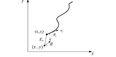
Deviation diagram order to improve the accuracy of the system model and avoid the lag of the control algorithm, a prediction module is designed on the actual movement trajectory of the vehicle. That is, the control system is based on the external environment, road information and the current vehicle movement state. Vehicle motion control predicts the displacement and heading deviation between the current actual position of the vehicle and the desired path, thereby controlling the steering wheel rotation to make the prediction deviation zero [6] there by achieving tracking of the desired path. For 𝑋 𝑝𝑟𝑒 = (𝑥 𝑝𝑟𝑒 , 𝑦 𝑝𝑟𝑒 ,𝑣 𝑝𝑟𝑒 ,𝑣 𝑦𝑝𝑟𝑒 , 𝜑 𝑝𝑟𝑒 , 𝜑 𝑝𝑟𝑒 ) [7].
\( {x_{pre }}=x+{v_{x}}×t×cosφ-{v_{y}}×t×sinφ,{y_{pre}}=y+{v_{y}}×t×cosφ+{v_{x}}×t×sinφ,{v_{xpre}}={v_{x}},{v_{ypre}}={v_{y}},{φ_{pre}}=φ+{φ^{∘}}×t,φ_{pre}^{ \prime }={φ^{ \prime }}, \) t(4)
Therefore, the deviation between the actual movement trajectory of the vehicle and the planned trajectory can be expressed as
𝑋 − 𝑋𝑟 = 𝐸𝑟𝑟(5)
It can be seen from vehicle dynamics analysis that \( \vec{X} \) Satisfies 𝑋 = 𝐴𝑋 + 𝐵𝑢, therefore, the vehicle’s planned path and actual movement.
The deviation 𝐸 𝑟𝑟 between paths satisfies: 𝐸𝑟 = 𝐶𝐸 𝑟𝑟 + 𝐷𝑢 So the goal of controlling vehicle motion at this time can be defined as determining the appropriate input 𝑢 so that 𝐸 𝑟𝑟 is as small as possible, thereby achieving the purpose of accurately controlling vehicle motion [8].
2.3. Longitudinal motion analysis
Longitudinal motion control is the basis for autonomous driving of intelligent driving vehicles. It completes the motion by controlling the driving or braking system of the vehicle, performs accurate and fast tracking according to the desired speed, and realizes the acceleration or deceleration of the vehicle established in the previous section. The premise of the intelligent vehicle lateral motion control strategy is to assume that the vehicle runs at a constant speed. However, during the actual movement of the vehicle, the vehicle needs to change its driving speed according to the actual movement environment and road conditions. Therefore, the movement speed of the actual vehicle does not always remain constant. Therefore, simple vehicle lateral movement control cannot fully demonstrate the driving conditions of intelligent vehicles in the actual environment (see Table 1 Simulation parameter).
Table 1. Stimulation parameters of this system
parameter name | parameter symbol | reference value |
Vehicle quality /𝑘𝑔 | m | 1412 |
Wheelbase /𝑚 | L | 2.91 |
Distance from front axle to center of mass /𝑚 | a | 1.015 |
Distance from rear axle to center of mass /𝑚 | b | 1.895 |
Vehicle moment of inertia /(𝑘𝑔⋅𝑚 2 ) | I | 1536.7 |
Front and rear tire side stiffness /(N/rad) | Cat=C | -110000 |
2.4. Simulation verification
2.4.1. Lateral motion control simulation. In order to verify the control effects of the longitudinal and lateral motion control systems of intelligent driving vehicles, Carsim is used to establish a vehicle motion model and set input and output signals, vehicle driving road conditions and other parameters. According to mathematical derivation, longitudinal and lateral motion control algorithms are established in Matlab/Simulink respectively, and joint simulation is performed (see Figure 3).
| |
Figure 3. Simulation results of lateral motion [9] | |
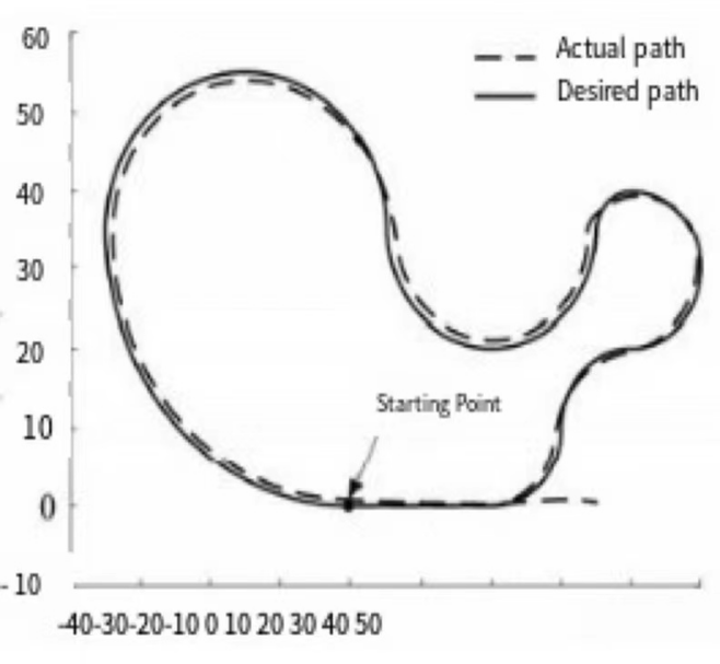
Under the action of the control system, the vehicle completes tracking of the desired path. At the starting point, the vehicle begins to move in a straight line, and the actual vehicle movement path completely coincides with the expected path. When the vehicle enters a curve, due to changes in road curvature, deviations occur between the actual vehicle movement trajectory and the expected path, especially when the road curvature appears. When the road curvature changes continuously, the deviation increases, and when the road curvature is a constant value, the motion deviation remains basically stable.
2.4.2. Longitudinal motion control simulation. Intelligent driving vehicle longitudinal motion control, the vehicle model is also established in Carsim software, and the vehicle is set to move in a straight line at this time, the throttle and brake control models are established in Matlab/Simulink , and a reasonable PID controller is designed , through repeated testing, it was determined that the PID controller parameters are 𝐾 𝑃 = 1, 𝐾 𝑑 =0.2, and then re-planned an expected displacement, velocity and acceleration curve that changes with time in Simulink , combined the Carsim model and the Matlab/Simulink model to establish a longitudinal motion control model, simulated it, and verified the longitudinal control algorithm. The simulation results are as shown in the Figure 4, 5 and 6.
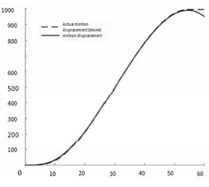
Figure 4. In this case simply justify the caption so that it is as the same width as the graphic [9]
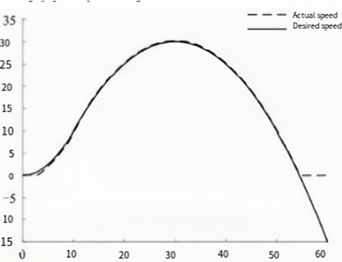
Figure 5. These two figures have been placed side-by-side to save space
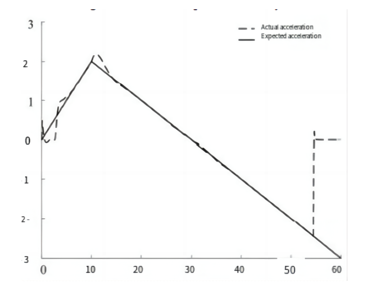
Figure 6. These two figures have been placed side-by-side to save space
(a) The displacement change curve of the simulated vehicle longitudinal motion from the start of simulation to the stop of the vehicle is recorded. The results show that the vehicle displacement controlled by PID is basically consistent with the expected displacement curve, and shows good displacement in both the starting stage and the parking stage. The ability to track changes in speed. As shown in Figure 5, the planned longitudinal speed of the vehicle starts to accelerate from time 0, and gradually decreases at 30 s, until the vehicle stops moving. The actual vehicle speed is basically consistent with the planned ideal speed. Figure 6 shows the vehicle acceleration change curve. During the vehicle’s starting acceleration stage, due to the acceleration mutation caused by inertia, a large deviation occurs between the actual vehicle acceleration and the planned curve. Subsequently, through the PID controller adjustment, the acceleration is very small. It quickly tends to be stable. At the 10th s, due to the sudden change in acceleration, a large deviation occurs between the actual motion and the planned curve. Subsequently, after adjustment by the PID controller [10], the actual acceleration and the planned acceleration are basically consistent until the vehicle stops.
3. Discussion
Intelligent vehicle motion simulation is a method of simulating vehicle movement using computer technology, which can help us better understand and study the behavior and performance of vehicles. Intelligent vehicle motion simulation has a wide range of applications in automotive engineering, traffic planning, and driver training.
Firstly, intelligent vehicle motion simulation can help automotive engineers design and optimize vehicle performance. By simulating different driving scenarios and road conditions, engineers can evaluate the handling, stability, and fuel economy of vehicles, among other indicators. They can make adjustments and improvements based on simulation results to enhance vehicle performance and safety.
Secondly, intelligent vehicle motion simulation is crucial for traffic planning. Traffic planners can use simulation technology to evaluate the effectiveness of various traffic schemes, such as road reconstruction, optimization of traffic signal lights, and planning of bus routes. They can predict traffic flow, congestion, and travel time through simulations, thereby formulating more scientific and effective traffic planning strategies.
Additionally, intelligent vehicle motion simulation can be used for driver training and driver behavior research. By simulating various driving scenarios, drivers can train in virtual environments to improve their driving skills and ability to respond to emergencies. Researchers can also use simulation technology to study driving behavior and the impact of factors such as driver attention and reaction time on traffic safety, providing a scientific basis for the formulation of traffic safety policies.
However, intelligent vehicle motion simulation also faces challenges and limitations. Firstly, simulation results may be affected by the accuracy of the model and parameter settings, necessitating precise model establishment and parameter calibration. Secondly, the simulation process requires substantial computing resources and time, especially for complex traffic scenarios and large-scale simulation systems, limiting the scale and efficiency of simulations. Moreover, simulation results are only approximations of real situations and may have certain errors and uncertainties [11].
In conclusion, intelligent vehicle motion simulation is a technology with extensive application prospects. It can help us better understand and study the behavior and performance of vehicles, providing scientific evidence for automotive engineering, traffic planning, and driver training. However, we also need to recognize the limitations of simulation technology and continuously improve and refine the models and algorithms to enhance the accuracy and reliability of simulations.
4. Conclusion
Through reasonable assumptions, this paper established a two-degree-of-freedom intelligent driving vehicle longitudinal and lateral dynamics model, discussed the longitudinal and lateral motion characteristics of the vehicle respectively, established different vehicle planning paths for longitudinal and lateral motion control, and used the liner quadratic regulator method and process identifier respectively. The control system controls and analyzes the horizontal and vertical movements of the intelligent vehicle. A prediction module is added when designing the control system. The control system will predict the movement trajectory of the vehicle in the next second, thereby improving the vehicle motion control effect and making the vehicle’s acceleration and braking softer and smoother. Simulation verification was carried out in conjunction with Carsim and Matlab/Simulink. The results showed that the two control methods have good control effects on vehicle longitudinal and lateral motion control. Through simulation, it can be seen that when an intelligent driving vehicle is running, the planned path and planned speed largely determine the smoothness of the vehicle. Especially under complex paths, good motion control is the key to the smooth operation of the vehicle. Therefore, when designing a motion control strategy for autonomous vehicles, it is necessary to consider not only the vehicle’s accurate tracking of the planned path and planned speed, but also the stability and smoothness of the vehicle’s driving. Through simulation research, this paper verifies the effectiveness of two different longitudinal and lateral control methods, and also provides a reference for designing longitudinal and lateral motion control strategies for autonomous vehicles. But at the same time, it should be noted that in order to facilitate simulation, this paper makes reasonable assumptions on the vehicle dynamics model. Therefore, the simulation results will deviate from the actual situation, and the effectiveness of the algorithm needs to be further verified in experiments; secondly, for automatic Path planning for driving a vehicle is a strict task. This article only uses simulation methods to obtain an ideal road. Curve, it will also affect the simulation results and needs to be improved in subsequent research.
References
[1]. Guo Jinghua, Li Keqiang, Luo Yugong. Review of research on intelligent vehicle motion control [J]. Journal of Automotive Safety and Energy Saving , 2016, 7(2): 151-159.
[2]. Yang Liu. Research on coupled longitudinal and transverse dynamics control of high-speed vehicles [D]. Chongqing : Chongqing University , 2006.
[3]. Wang Hao. Research on intelligent vehicle motion control based on lateral and longitudinal comprehensive control [D]. Nanjing : Nanjing University of Aeronautics and Astronautics, 2016.
[4]. Gao Linlin, Tang Fengmin, Guo Peng, et al . Research on improved LQR method for automatic driving lateral motion control [J]. Mechanical Science and Technology , 2021,40(3): 435-441.
[5]. Xiong Lu, Yang Xing, Zhuo Guirong, et al . Review of the development status of motion control of unmanned vehicles [J]. Transactions of the Chinese Society of Mechanical Engineering , 2020, 56(10): 127-143.
[6]. Yin Zhishuai, He Jiaxiong, Nie Linzhen, et al. Longitudinal adaptive control of autonomous vehicles based on optimization algorithm [J]. Journal of System Simulation , 2021, 33 (2): 409-420.
[7]. Guo Bixi, Wang Wei, Tao Xiaosong, et al. Longitudinal speed following control strategy for intelligent vehicles considering driver characteristics [J]. Mechanical Science and Technology, 2021,
[8]. Li Bo, LI Shuangshuang, BAI Yanfei, et al. Collaborative Control of Active Front wheel Steering and Direct Yaw Moment Based on Model Prediction [J]. Automotive Technology, 2023(1): 37-43.
[9]. Guo Jinghua, Luo Yugong, Li Keqiang. Collaborative design of intelligent vehicle motion control system [J]. Journal of Tsinghua University (Natural Science Edition), 2015(7): 761-768.
[10]. Yan Shengkai, Huang Boyi. Motion Simulation and Analysis of four-wheel Steering Mechanism based on MATLAB/Simulink [J]. Agricultural Equipment and Vehicle Engineering, 201, 59(5): 58-62.
[11]. Zhou Junwu, Qin Liren, Yang Hang. Research on parallel Parking of Vehicles based on “pure tracking Algorithm” [J]. Automotive Electrical Appliances, 2022(6): 1-3, 7.
Cite this article
You,Y. (2024). Design analysis of simulated smart cars at different cases. Theoretical and Natural Science,31,167-174.
Data availability
The datasets used and/or analyzed during the current study will be available from the authors upon reasonable request.
Disclaimer/Publisher's Note
The statements, opinions and data contained in all publications are solely those of the individual author(s) and contributor(s) and not of EWA Publishing and/or the editor(s). EWA Publishing and/or the editor(s) disclaim responsibility for any injury to people or property resulting from any ideas, methods, instructions or products referred to in the content.
About volume
Volume title: Proceedings of the 3rd International Conference on Computing Innovation and Applied Physics
© 2024 by the author(s). Licensee EWA Publishing, Oxford, UK. This article is an open access article distributed under the terms and
conditions of the Creative Commons Attribution (CC BY) license. Authors who
publish this series agree to the following terms:
1. Authors retain copyright and grant the series right of first publication with the work simultaneously licensed under a Creative Commons
Attribution License that allows others to share the work with an acknowledgment of the work's authorship and initial publication in this
series.
2. Authors are able to enter into separate, additional contractual arrangements for the non-exclusive distribution of the series's published
version of the work (e.g., post it to an institutional repository or publish it in a book), with an acknowledgment of its initial
publication in this series.
3. Authors are permitted and encouraged to post their work online (e.g., in institutional repositories or on their website) prior to and
during the submission process, as it can lead to productive exchanges, as well as earlier and greater citation of published work (See
Open access policy for details).
References
[1]. Guo Jinghua, Li Keqiang, Luo Yugong. Review of research on intelligent vehicle motion control [J]. Journal of Automotive Safety and Energy Saving , 2016, 7(2): 151-159.
[2]. Yang Liu. Research on coupled longitudinal and transverse dynamics control of high-speed vehicles [D]. Chongqing : Chongqing University , 2006.
[3]. Wang Hao. Research on intelligent vehicle motion control based on lateral and longitudinal comprehensive control [D]. Nanjing : Nanjing University of Aeronautics and Astronautics, 2016.
[4]. Gao Linlin, Tang Fengmin, Guo Peng, et al . Research on improved LQR method for automatic driving lateral motion control [J]. Mechanical Science and Technology , 2021,40(3): 435-441.
[5]. Xiong Lu, Yang Xing, Zhuo Guirong, et al . Review of the development status of motion control of unmanned vehicles [J]. Transactions of the Chinese Society of Mechanical Engineering , 2020, 56(10): 127-143.
[6]. Yin Zhishuai, He Jiaxiong, Nie Linzhen, et al. Longitudinal adaptive control of autonomous vehicles based on optimization algorithm [J]. Journal of System Simulation , 2021, 33 (2): 409-420.
[7]. Guo Bixi, Wang Wei, Tao Xiaosong, et al. Longitudinal speed following control strategy for intelligent vehicles considering driver characteristics [J]. Mechanical Science and Technology, 2021,
[8]. Li Bo, LI Shuangshuang, BAI Yanfei, et al. Collaborative Control of Active Front wheel Steering and Direct Yaw Moment Based on Model Prediction [J]. Automotive Technology, 2023(1): 37-43.
[9]. Guo Jinghua, Luo Yugong, Li Keqiang. Collaborative design of intelligent vehicle motion control system [J]. Journal of Tsinghua University (Natural Science Edition), 2015(7): 761-768.
[10]. Yan Shengkai, Huang Boyi. Motion Simulation and Analysis of four-wheel Steering Mechanism based on MATLAB/Simulink [J]. Agricultural Equipment and Vehicle Engineering, 201, 59(5): 58-62.
[11]. Zhou Junwu, Qin Liren, Yang Hang. Research on parallel Parking of Vehicles based on “pure tracking Algorithm” [J]. Automotive Electrical Appliances, 2022(6): 1-3, 7.