


1. Introduction
Questions like “How do airplanes fly” are answered by students in middle school around the globe, while teachers provide students with a clear and understandable explanation based on a simplification of Bernoulli’s equation. However, is it that easy to address the question or is it because we only see the superficial reason? The latter one may be more possible. The realm of aerodynamics is far more complex than most people could imagine, which could even trigger debates among excellent scientists who hold different views on the phenomena. Being more and more interested in such a debatable question, I decided to start researching this topic: aerodynamics of airplane wings.
The first chapter of the essay offers a simplified analysis of airplane wings, while the next part serves as a summary of different theories populating the field of science now. During the process of research, I sort three main clusters for the varied opinions. The first is based on Bernoulli’s equation, the second applies Newton’s third law, and the last involves the concept of the Coanda effect. After closely examining these explanations, it is easier to find some flawed details hidden in the seemingly correct ideas. The essay is therefore possessing significance in different fields. For education, it offers the public valuable insights into the principles governing flight. At the same time, researchers who particularly work on airplane technology may be innovated for refinements on the design of wing structures or other parts.
2. Simplified force analysis of airfoils
The dream of human flight has been realized through the mastery of aerodynamics, a science that encompasses the principles of lift and drag, so it is necessary to acquire the basic knowledge of how forces distribute on wings.
In physics lessons, everyone has once completed force analysis on an object, which is the same way around here when scientists try to figure out how to decompose the forces acting on the two-dimensional airfoil when it is flying [1]. There are mainly two obvious forces acting on airplane wings: drag in the horizontal direction and lift in the vertical, which will be discussed in the later chapters.
2.1. Introduction to Drag force
Drag force is everywhere. It can have a huge impact on the performance of vehicles, fuel consumption, and productivity. Most of the time, it is not desirable, and so does it in aerodynamics.
As shown in Figure 1, drag force opposes an aircraft’s forward motion through the air. It is a consequence of the interaction between the airfoil and the air molecules it encounters during flight [2]. Drag forces are the resultant of friction drag and pressure drag in the direction of the flow, and the following parts will introduce them separately in detail, and also how to reduce them for higher stability.
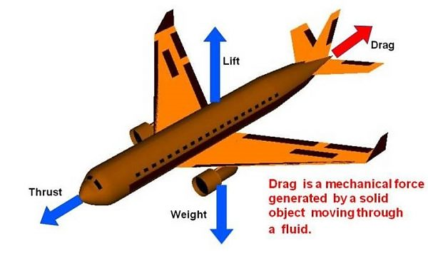
Figure 1. Drag is a mechanical force generated by a solid object moving through a fluid [2].
2.2. Pressure Drag
Simultaneously, pressure drag created by pressure stress acts opposite to the object’s surface, and it is brought about by the pressure difference between the front and back of an object.
At the point when the fluid boundary layer is confined from the liquid surface, the pressure drag will increment altogether, and the detachment will likewise bring undesirable vibrations, which is called boundary layer separation.
Why it happens? As the fluid passes over the surface, it starts to speed up and hence forms a favorable pressure gradient. By and by, when the stream goes over a specific point, it will decelerate and transform an adverse pressure gradient. At the point when the pressure increase is adequately enormous, as depicted in Figure 2, the flow will switch its direction, but it can’t travel in the opposite direction, so it detaches from the surface, leading to significant drag forces [3].
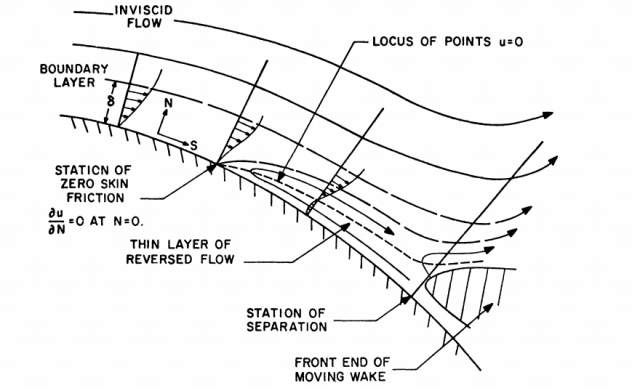
Figure 2. Upstream moving separation [3].
After finding out how flow separation occurs, we need to consider how to minimize it. Theoretically, the flow could be either laminar or turbulent. Laminar flow is a kind of movement in which fluid particles follow a well-defined path and form straight parallel lines. On the contrary, turbulent flow is mixing. Fluid particles move in a zigzag way which is responsible for the high energy cost as presented in Figure 3 [4].
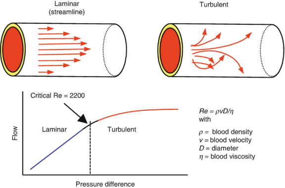
Figure 3. Graph representing flow vs pressure difference for laminar and turbulent flow [4].
It isn’t hard to understand that there are significant differences in properties between the two types of flow, which directly affects the formation of the boundary layer. Typically, in a huge degree of mass interchange, a laminar boundary layer would become too thick to attach the fluid particles. On the other hand, when the liquid is turbulent, the fluid should stay connected to the surface, which implies that the flow separation won’t end so quickly or cause an excess of vibration [5]. That is the reason why there is a little vortex generator on airfoils.
2.3. Friction Drag
Friction drags, brought about by shear pressure, acts tangential to the item’s surface. Due to a fluid’s viscosity, there are inevitably friction forces forming, leading to the creation of shear stress.
Although turbulence could delay flow separation as introduced in the previous section, it is the opposite effect for friction drag. During the great extent of mass interchange, a turbulent boundary layer is often thicker which will help it from a steeper velocity gradient, as shown in Figure 4. The velocity gradient at the same time leads to internal shear stresses acting on the surface. In that case, since the velocity gradient of turbulent flow is greater, the friction drag created by it is also more significant.
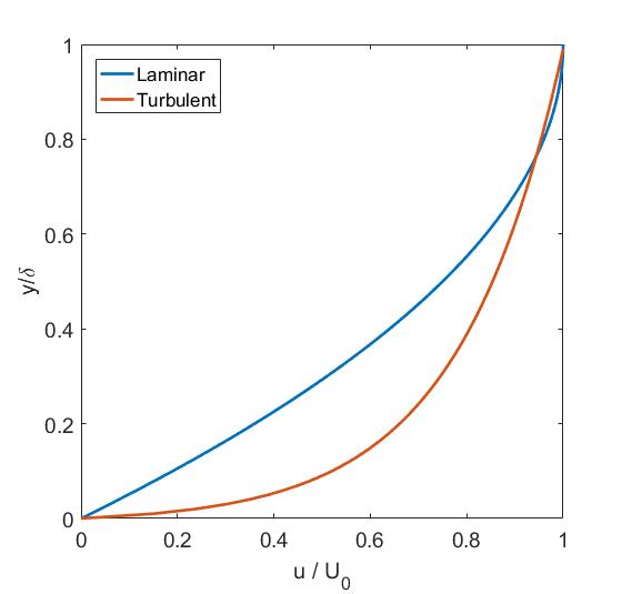
Figure 4. Velocity profile of laminar versus turbulent boundary layer [6].
2.4. What is lift?
Streamlined powers following up on flying objects are named the lift toward the path normal to the flight, which holds an airplane in the air, as presented in Figure 5. The lift can be created by any piece of the plane, yet the greater part of the lift on a typical carrier is produced by the wings [3]. However, finding out the formation of lift forces has long been a challenge and quite a debate among scientists, so what can explain the mystery lying under the truth of lift forces that has caused debates over decades?
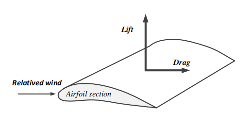
Figure 5. Geometry of an aircraft wing [3].
3. What makes planes stay in the air?
3.1. What’s wrong with popular explanation?
Middle school students are undeniably instructed that planes fly because of Bernoulli’s principle, which says that when velocity goes up, the pressure is brought down. Hence, a wing produces lift as the air goes quicker over the top and generates a region of low pressure. Nevertheless, such a theory raises inquiries from many people, and the essential question is: why does the air go quicker over the airfoil? This is where the well-known explanation of lift falls apart.
The usual claim, based on Bernoulli’s Equation to explain why the air goes faster over the top of the wing states that pressure differential pushes the airplane upward, creating a lift. That is the point at which the air isolates at the main edge, the part that goes over the top should merge at the following edge with the part that goes under the base, as presented in Figure 6. This is the alleged “rule of equivalent travel times”. Nevertheless, think carefully about this theory, a large flaw may appear: if the airfoil shapes determine the pressure difference that leads to lift, why could some airplanes fly upside down? This theory fails to offer a comprehensive explanation as it is proved wrong by experiments.
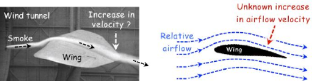
Figure 6. The alleged increase in relative airflow speed has not been measured [7].
No evidence could prove the correctness of this so-called “principle of equal transit times” theory. The separated air doesn’t meet at the following edge simultaneously. As depicted in Figure 7, the wind current over a wing in a reenacted air stream. In the simulation, shaded smoke is presented occasionally. Close examination uncovers that the air going under the wing is dialed back from the “free-stream” speed of the air, which refutes the guideline of equivalent send times directly [8].
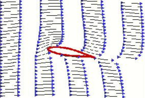
Figure 7. Simulation of the airflow over a wing in a wind tunnel [8].
Moreover, another noticeable fact that is overlooked matters as well: Bernoulli’s equation applies only along a streamline, as shown in Figure 8, without the explicit relationship between the pressure and velocity of neighboring streamlines [9]. Therefore, the prerequisite to base the explanation for lift on Bernoulli’s principle has failed, while that of course doesn’t affect the rightness of Bernoulli’s Equation itself.
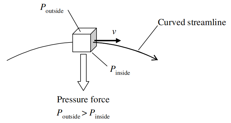
Figure 8. Fluid particles travel along a curved streamline [9].
3.2. Explanation based on the Coanda Effect
The Coanda’s effect expresses that a moving stream of liquid in touch with a curved surface will more often follow the curvature of the surface instead of keep traveling in a straight line as presented in Figure 9 [10].
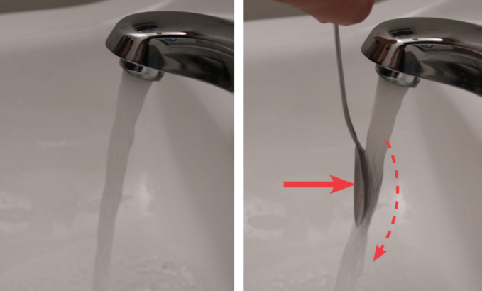
Figure 9. Coanda effect [10].
In this case, as the wing is curved, the airflow will follow the curvature of the wing, as shown in Figure 10. A fluid follows a curved surface due to its viscosity: the resistance to flow which also gives the air a kind of “stickiness.” Viscosity in air is tiny however it is enough for the air particles to adhere to the surface, as long as the general speed between the surface and the air particles right above it is precisely zero [3].
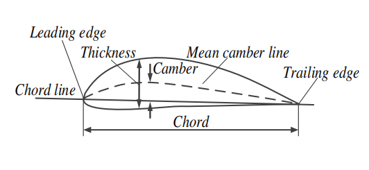
Figure 10. Sketching of airfoil design [3].
Since airfoil is a curvature, the fluid particles must experience a centripetal force when constantly changing direction, resulting in a pivotal role played by particles at the upper surface. When passing the trailing edge, the airflow will be bent by the airfoil, which pulls the air above it and leads to an acceleration down to the airfoil, according to Newton’s third law, so that a lower-pressure region is formed. Nevertheless, only focusing on Newton’s third law of action and reaction is not enough as it is the pressure gradient that allows the airflow to follow the shape of the surface, as shown in Figure 11 [11]. Therefore, throughout the whole flight, the pressure gradient is produced by the airflow, meaning that the condition for the Coanda effect is satisfied, and thus creates the lift [12].
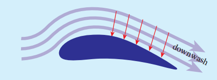
Figure 11. The air layer accelerated [12].
3.3. Angle of Attack
The angle of attack of the wing, a concept that indicates how tilted the wing is concerning the oncoming air, plays an important role in influencing the effectiveness of the Coanda effect as airflow is rotated relative to the airstream.
The graph records a few cases in which angles of attack are expanding. It is more than clear to sum up that the wind current will never again follow the curvature of the wing when the angle becomes too great. As displayed in this diagram, an angle of attack forms a little vacuum simply behind the wing. As shown in Figure 12, at the point when the wind airflow surges in to occupy this space, called cavitation, it causes weighty vibrations on the wing and enormously diminishes the proficiency of the wing [13]. Consequently, airplane wings are by and large calculated at a moderate and reasonable point for the wing to effectively coordinate the wind current downward, which thus pushes up on the wing, creating lift, as explained in 3.2.
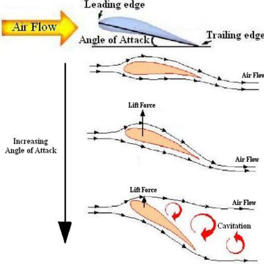
Figure 12. Flowchart of airflow [13].
One more diagram is displayed below to introduce the coefficient of lift for a typical wing as an element of the effective angle of attack. Conclusively, the lift starts to diminish at an angle of attack around 15 degrees just as Figure 13 presented [14].
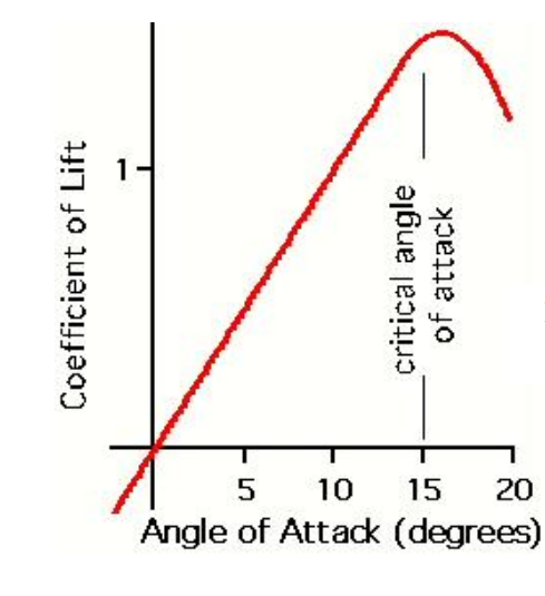
Figure 13. Coefficient of lift versus the effective angle of attack [14].
More surprisingly, the angle of attack might sometimes be negative, as depicted in the model in Figure 14 [9], which will happen when an airplane is performing an inverted flight--the upside-down flight! In this scenario, the lift is sufficiently generated by the centripetal acceleration of the air so that it counteracts the downward force created by the air striking the top surface of the wing.
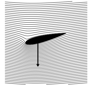
Figure 14. Negative angle of attack [9].
4. Conclusion
Overall, sometimes a real-life situation couldn’t be explained through a simple explanation for granted, just as those examples described in textbooks. The geometry of airplanes is so intricate that even scientists are debating with each other, while this article aims to give it a try to present a simplified but comprehensive explanation of aerodynamic lift instead of continuing to spread out the misleading approximation of Bernoulli’s equation to the public. As above analysis and evaluation, it is confirmed that the theory will be more accurate if we can try to explain the aerodynamic situation through the Conada effect, involving key information such as pressure gradient and angle of attack.
References
[1]. Chattot, Jean Jacques (2020). The origin of lift â understanding lift. International Journal of Aerodynamics, 7(1), 83. doi:10.1504/ijad.2020.107176.
[2]. Beginners guide. What is Drag? https://www1.grc.nasa.gov/beginners-guide-to-aeronautics/ what-is-drag/
[3]. Triet, Nguyen Minh et al, (2015). Aerodynamic Analysis of Aircraft Wing. VNU Journal of Science: Mathematics – Physics, Vol. 31, No. 2 (2015) 68-7568.
[4]. Groh, Rainer, (2016). Boundary Layer Separation and Pressure Drag.
[5]. Laminar Fluid and Turbulent fluid, Fluid Dynamics https://theconstructor.org/fluid-mechanics/ laminar-turbulent-flow/559432/
[6]. https://aerospaceengineeringblog.com/boundary-layer-separation-and-pressure-drag/
[7]. Landell-Mills, Nicholas. The flawed analysis of wind tunnel experiments. 2023.
[8]. Anderson David, Eberhardt Scott, (2010). How Airplanes Fly: Physical Description of Lift. The Aviation History Online Museum.
[9]. Holger, Babinsky, (2003). How do wings work? 10.1088/0031-9120/38/6/001.
[10]. Foam, Wing. Principles of light. National Aeronautics and Space Administration.
[11]. www.nasa.gov.
[12]. Regis, Ed, (2020). No One Can Explain Why Planes Stay in the Air.
[13]. Soares, J Silva1 et al, (2010). Understanding wing lift. Features.IOP Publishing Ltd.
[14]. DiscoverHover. Bernoulli’s Principle and the Coanda Effect. DiscoverHover CURRICULUM GUIDE #8. https://www.discoverhover.org/infoinstructors/guide8.htm
Cite this article
Fu,M. (2024). Research on the aerodynamic causes of airplane wings. Theoretical and Natural Science,36,77-84.
Data availability
The datasets used and/or analyzed during the current study will be available from the authors upon reasonable request.
Disclaimer/Publisher's Note
The statements, opinions and data contained in all publications are solely those of the individual author(s) and contributor(s) and not of EWA Publishing and/or the editor(s). EWA Publishing and/or the editor(s) disclaim responsibility for any injury to people or property resulting from any ideas, methods, instructions or products referred to in the content.
About volume
Volume title: Proceedings of the 2nd International Conference on Mathematical Physics and Computational Simulation
© 2024 by the author(s). Licensee EWA Publishing, Oxford, UK. This article is an open access article distributed under the terms and
conditions of the Creative Commons Attribution (CC BY) license. Authors who
publish this series agree to the following terms:
1. Authors retain copyright and grant the series right of first publication with the work simultaneously licensed under a Creative Commons
Attribution License that allows others to share the work with an acknowledgment of the work's authorship and initial publication in this
series.
2. Authors are able to enter into separate, additional contractual arrangements for the non-exclusive distribution of the series's published
version of the work (e.g., post it to an institutional repository or publish it in a book), with an acknowledgment of its initial
publication in this series.
3. Authors are permitted and encouraged to post their work online (e.g., in institutional repositories or on their website) prior to and
during the submission process, as it can lead to productive exchanges, as well as earlier and greater citation of published work (See
Open access policy for details).
References
[1]. Chattot, Jean Jacques (2020). The origin of lift â understanding lift. International Journal of Aerodynamics, 7(1), 83. doi:10.1504/ijad.2020.107176.
[2]. Beginners guide. What is Drag? https://www1.grc.nasa.gov/beginners-guide-to-aeronautics/ what-is-drag/
[3]. Triet, Nguyen Minh et al, (2015). Aerodynamic Analysis of Aircraft Wing. VNU Journal of Science: Mathematics – Physics, Vol. 31, No. 2 (2015) 68-7568.
[4]. Groh, Rainer, (2016). Boundary Layer Separation and Pressure Drag.
[5]. Laminar Fluid and Turbulent fluid, Fluid Dynamics https://theconstructor.org/fluid-mechanics/ laminar-turbulent-flow/559432/
[6]. https://aerospaceengineeringblog.com/boundary-layer-separation-and-pressure-drag/
[7]. Landell-Mills, Nicholas. The flawed analysis of wind tunnel experiments. 2023.
[8]. Anderson David, Eberhardt Scott, (2010). How Airplanes Fly: Physical Description of Lift. The Aviation History Online Museum.
[9]. Holger, Babinsky, (2003). How do wings work? 10.1088/0031-9120/38/6/001.
[10]. Foam, Wing. Principles of light. National Aeronautics and Space Administration.
[11]. www.nasa.gov.
[12]. Regis, Ed, (2020). No One Can Explain Why Planes Stay in the Air.
[13]. Soares, J Silva1 et al, (2010). Understanding wing lift. Features.IOP Publishing Ltd.
[14]. DiscoverHover. Bernoulli’s Principle and the Coanda Effect. DiscoverHover CURRICULUM GUIDE #8. https://www.discoverhover.org/infoinstructors/guide8.htm