


1. Introduction
The intelligent line-following vehicle is a traditional path-tracking robot, which could drive along the settled path without hand control and this type of robot has been widely used in the industry field [1-2]. For example, a line-following robot was created to provide comfortable and time-saving public transportation for passengers to reduce the use of private cars [3], in which fuzzy logic is used for controlling the motion of the robot. However, the first version of the line-following vehicle is based on bang-bang control, which could only control two states of the vehicle and could not control the speed. There are only two directions that the vehicle could drive- turn left or turn right. Though the vehicle could drive along the designed path, the process is not stable. Therefore, according to the knowledge recently learned, the line-following vehicle based on the PID control algorithm is proposed, which has the advantages of simple structure, easy adjustment, high stability, and fast feedback [4-5]. As a control algorithm, it has been widely and successfully used in industrial applications in the past few decades [6]. This type of algorithm could control the speed. The PID algorithm will obtain and tackle the relative position, continuously accumulated relative position and the difference between the relative position of two consecutive moments. Information about the process of building the car and the algorithm will be described in the following sections.
2. Method
The line following vehicles was designed and built to run the path. Which is demonstrated in the method part.
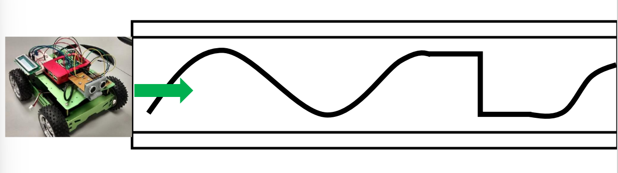
Figure 1. The track of the black line.
The intelligent vehicle needs to drive along the black line from left to right in the environment represented in Figure 1. Therefore, it includes a lot of knowledge that needs to be understood. The following is the whole process.
2.1. Vehicle building
There are many materials used to make these two carts. The following are the materials and their parameters.
Table 1. Components and parameters.
NO | components and parameters | |
1 | Bracket-1 L (Aluminum extrusion 6061) | 200*35*20mm*3.0mm |
2 | Bracket-2 L (Aluminum extrusion 6061) | 135*35*20mm*3.0mm |
3 | 25 motor frame*4 | Silver |
4 | The board of H-bridge 6.223 cm * 2.515 cm | |
5 | The aluminum silver frame of the vehicle 155*200 | (Silver)155*200 |
6 | FT232RL USB to Serial board | |
7 | The baseboard of the vehicle is 12.7cm * 12.7cm | |
8 | Vehicle wheel medium 65mm | 65mm*27mm |
9 | Battery 18650 2600mAh | 2600mAh, 3.7V |
10 | Arduino Nano with USB cable | |
11 | Power switch MTS102 250V 3A | |
12 | 25GA-370 motor with encoder | 6V, 280rpm |
When the materials were prepared, the construction of the car began. The process of building was completed within a few days, and the inspection of each component was the first step. The next step is the most critical, which is to connect the Arduino Nano board to the controller. The controller model is ATMega328PB IC, whose host firmware receives commands through the serial interface to determine the direction and velocity of the motor. The serial communication between the Arduino Nano board and controller could be SPI, I2C, and UART. Then was the frame building of the vehicle, the four motors and four wheels were connected, all of which were framed in the Vehicle. H-bridge Boards and Baseboard installation were achieved in the last second step. Then fix the battery and its holder on the top of the car, and the vehicle building was achieved. Here was the appearance of the vehicle.
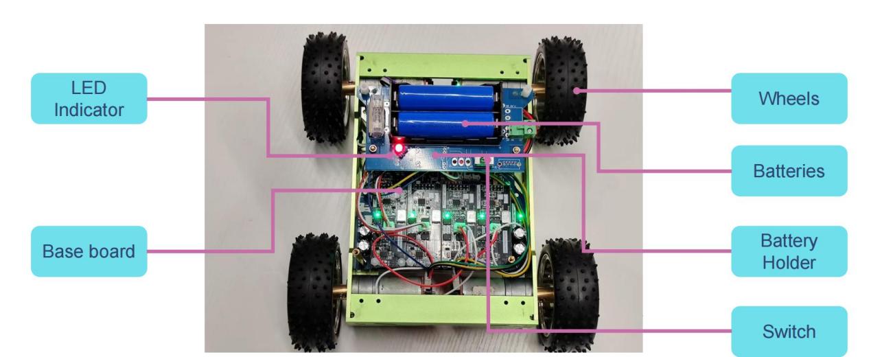
Figure 2. The appearance of the vehicle.
2.2. Compilers of Arduino
Arduino compiler is selected as Arduino IDE, IDE (Integrated Development Environment), is an Integrated Development Environment, the compiler to add connector + other equivalent of editor. Arduino IDE is Arduino team provided by a specially designed for the Arduino programming software, use it, the code could be uploaded to Arduino board, which can transfer commands from computer to hardware.It also supports a variety of development board, such as the Arduino Uno, Mega, Nano, etc.
2.3. Sensor
The infrared sensor model used in this experiment is SF-8CHIDTS. The sensor is internally equipped with 8 TCRT5000 infrared sensors aand corresponding output indicator lights. In working mode, the infrared transmitter will continuously send infrared. When infrared is received, the output signal is low and the output indicator light is on. If there is no or insufficient infrared reflection (i.e. encountering a black line), the output signal of the sensor will become high and the output indicator light will turn off.
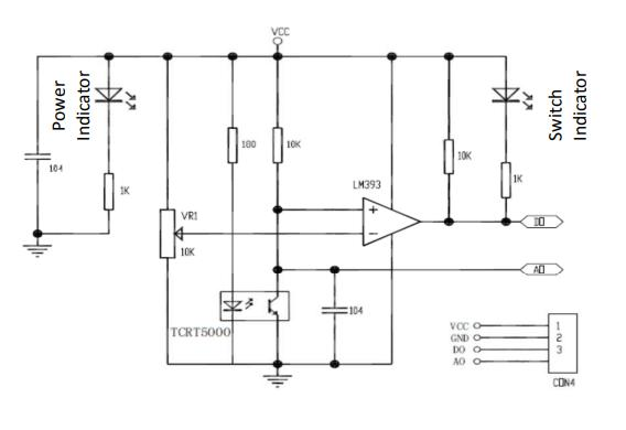
Figure 3. The internal circuit of the sensor.
Therefore, when the intensity of the reflected light is not high enough or there is no reflected light, the photosensitive transistor will remain closed. At this point, the A0 pin would be provided with a high level. Therefore, the module will remain at a high level. When the intensity of the reflected light is large enough, the photosensitive transistor will be turned on, and the current will split, with a portion of the current flowing to the ground. Therefore, at this point, the module will output a low-level signal. In order to obtain sensor data, we use an analog-to-digital converter (AD converter) on STM8S105C4 to collect sensor data and transmit the data to the main control board through the I2C communication protocol. Then, by using the weight averaging method and the Arduino IDE's PID control algorithm, the vehicle can achieve precise routing tasks [7-9].
2.4. Weight average
The concept of this method is to multiply the measured values of each sensor by the corresponding weights, and then sum them to obtain an overall value. Finally, divide the overall value by the total number of sensors to obtain a weighted average. In this experiment, we used 8 sensors. We set the center between the fourth and fifth sensors as the center of the entire X-axis and set corresponding X-coordinate values for each sensor. The following is X-coordinate values of each sensor.
Table 2. Corresponding locations for the eight sensors.
The order of the sensor | Location(mm) |
1 | 43.75 |
2 | 31.25 |
3 | 18.75 |
4 | 6.25 |
5 | -6.25 |
6 | 18.75 |
7 | -31.25 |
8 | -43.75 |
Then, in the next section, the analog signal output of the SF-8CHIDTS sensor will be measured and recorded when the black line is not encountered and when it is encountered. Next, the position of the black line relative to the car could be obtained by combining the output of analog signals for each sensor. Then, multiply the analog signal output of each sensor by its position value, and all values were added up; Finally, divide the above sum value by the cumulative analog signal output of each sensor to obtain the relative position of the black line with the center of SF-8CHidTS. When the relative position of the vehicle is calculated, the formula of this method will be used.
\( Distance=\frac{\sum _{j=1}^{8}{value_{j}}*{weight_{j}}}{\sum _{j=1}^{8}{value_{j}}}\ \ \ (1) \)
2.5. PID control
The position data obtained can be transmitted to the Arduino nano board, and then the tracking of the black line can be realized after processing by the PID algorithm. The introduction of PID and its implementation process are as follows.
KP, KI, and KD represent proportional feedback coefficient, integral feedback coefficient, and differential feedback coefficient, respectively.
KP is used for rapid response and error reduction, which can effectively reduce system errors. KI is mainly used to ameliorate the steady-state response of the system and diminish steady-state errors. KD, on the other hand, is used to improve the dynamic response speed of the system and plays an adaptive adjustment role when the error changes significantly. These parameters can be used to perform relevant calculations on input bias for parameter adjustment in feedback control systems.
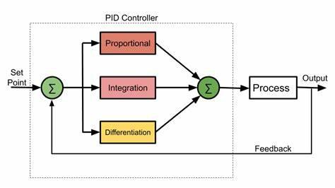 Figure 4. Working on PID.
The following is the calculation formula for PID.
\( u(t)={K_{p}}e(t)+{K_{i}}\int _{0}^{t}e(τ)dτ+{K_{d}}\frac{de(t)}{dt}\ \ \ (2) \)
Based on the above formula, U(t) is responsible for the control quantity (controller output); e(t) is the deviation between the controlled quantity and the designed values. Kp, Ki, and Kd have been introduced before.
Then, combine this algorithm with the relative position of the obtained black line. The vehicle could achieve line following. Here was the code combined with PID mode.
\( error = 0 ; \)
\( errorSum = 0 ; \)
\( errorOld = 0 ; \)
\( float PID (float lineDist) \)
\( \lbrace \)
\( errorOld = error ; \)
\( error =lineDist ;\ \ \ (3) \)
\( errorSum += error ; \)
\( float proportional = error * Kp ; \)
\( float integral = errorSum * Ki ; \)
\( float differential = ( error – errorOld ) * Kd ; \)
\( float output = proportional + integral + differential ; \)
\( return output ; \)
\( \rbrace \)
Directly multiply the relative position by the Kp value, use the continuously accumulated relative position for integral control calculation, and use the difference between the relative positions of adjacent two moments for differential control algorithm. Then there is the debugging of Kp, Ki, and Kd values, allowing the car to complete the entire track more smoothly.
3. Result
The window monitor monitors and records the analog signal outputs of eight sensors in the SF-8CHIDTS system to observe whether there are black lines, and can record them in both the presence and absence of black lines. The following figure shows the analog signal output values of these sensors.
\( 11:29:26.967 - \gt 968 \)
\( 11:29:26.967 - \gt 982 \)
\( 11:29:26.967 - \gt 985 \)
\( 11:29:26.967 - \gt 985 \)
\( 11:29:26.967 - \gt 985 \)
\( 11:29:26.967 - \gt 985 \)
\( 11:29:26.967 - \gt 986 \)
\( 11:29:26.967 - \gt 986\ \ \ (4) \)
\( 11:30:51.752 - \gt 365 \)
\( 11:30:51.752 - \gt 365 \)
\( 11:30:51.752 - \gt 365 \)
\( 11:30:51.752 - \gt 365 \)
\( 11:30:51.752 - \gt 365 \)
\( 11:30:51.752 - \gt 365 \)
\( 11:30:51.752 - \gt 365 \)
\( 11:30:51.752 - \gt 365 \)
By integrating the coordinate values of every sensor on the x-axis of the vehicle and the computing method of the mean weight, the position of the black line relative to eight sensors can be determined. Next, by combining relative position information with the PID algorithm, it is possible to achieve a linear following of the aircraft in a relatively stable attitude. The following is the process of debugging the three parameters in the PID controller.
Table3. The process of debugging Kp, Ki, and Kd.
Number of adjustments | Kp | Ki | Kd | Outcome |
1.1 | 3.2 | 0 | 0 | When the vehicle enters a bend, the speed becomes very slow and there is a noticeable stall phenomenon, which prevents it from smoothly passing the first sharp turn. |
2.1 | 3.2 | 0 | 0 | The result is similar to the first situation |
3.1 | 3.2 | 0.15 | 0 | Although the speed of the vehicle entering the curve is still very slow, the stall phenomenon is significantly reduced when passing through other large turns. However, the vehicle was still unable to successfully pass the first sharp turn. |
4.1 | 3.2 | 0.3 | 0 | The result is similar to the third situation |
5.1 | 3.2 | 0.3 | 0.5 | The first sharp turn was successfully passed and the stall situation was obviously reduced. But the second sharp turn failed to pass. |
6.1 | 3.2 | 0.3 | 1 | In the end, all the bends were successfully passed |
After multiple adjustments, the car finally successfully passed all the curves and successfully completed the task of following the line. Now, the vehicle could travel smoothly along the black line.
4. Discussion
By using the analog signal outputs of eight SF-8CHIDTS sensors and combining them with the average weight, we can calculate the relative distance of the black line. At the same time, with the help of PID controllers, we can also accurately control the driving of the car and achieve success in completing the task of following the line. Therefore, the tracking vehicle was completed successfully. However, this is the most basic version of the car, there is still a lot of upgrading to do. There are still some potential challenges to overcome. For example, since the road surface used for testing is flat, it is also necessary to test the performance of the car when it meets an uneven road surface. At the same time, according to Yukun's article [3], when the road surface is uneven, the stability of the car will be affected. At the same time, when there are obstacles on the road, the car will not be able to change its track and hit it, so the algorithm needs to be further modified to enable the car to realize the obstacle detection function.
5. Conclusion
Bang-bang control is a basic version of the control that could achieve the function of line-following. However, there are many limits to bang-bang control. For instance, the process of line-following is unstable, and the vehicle would vacillate to the left and right. Therefore, the vehicle based on PID control is presented in this article. This paper affords the process of preparation and testing. The appearance of the finished trolley is also provided in this article. In this experiment, the vehicle is controlled by the program complied with by Arduino and the aim of the vehicle is to find and track the black line surrounded by the white ground. The PID control and the codes are also demonstrated in the article. The result of the experiment is that after adjusting the values of parameters for PID, the vehicle could achieve the basic line-following function. However, the line-following vehicle is the basic version, and there are still some situations to consider. For example, when the ground is not flat or there are some obstacles in front of the vehicle. Therefore, it is necessary to improve the program and add different kinds of situations to test the vehicle. In the future, this control can be improved from these aspects. From the algorithm, GA (genetic Algorithm) [10], ACO (Ant Colony Optimization) [5], and PSO (Particle Swarm Optimization) algorithms [11] could be used to adjust PID parameters more effectively. From the hardware facilities, can add other sensors such as light sensors, ultrasonic sensors [3], etc., for more accurate transmission of road conditions; From the software facilities, Simulink and other software can be used to simulate road conditions, saving time [12].
References
[1]. Ozdemir Y, Sezgin A, Yüksel T. (2007). Çizgi izleyen gezgin bir robotun incelenmesi ve gerçeklenmesi. Proceeding of the 6th Symposium on Automation; 21-24.
[2]. Iren K. (2013). Improvement of industrial path following robot [dissertation]. Hacettepe University.
[3]. O. Gumus, M. Topaloglu and D. Ozcelik. (2016). The use of computer-controlled line follower robots in public transport. 12th International Conference on Application of Fuzzy Systems and Soft Computing, Austria, 202-208.
[4]. W. Zhang. (2010). Increment PID controller based on immunity particle swarm optimization algorithm. Microcomputer Information, vol. 28, no. 7, 67-69.
[5]. W. Liao, Y. Hu, H. Wang. (2014). Optimization of PID control for DC motor based on artificial bee colony algorithm. IEEE International Conference on Advanced Mechatronic Systems. 23-27.
[6]. R. ÇOBAN, Ö. ERÇIN. (2012). Multi-objective Bees Algorithm to Optimal Tuning of PID Controller. Cukurova University Journal of the Faculty of Engineering and Architecture. Vol. 27. No. 2. 13-26.
[7]. J. Chaudhari, A. Desai and S. Gavarskar. (2019). Line Following Robot Using Arduino for Hospitals. 2nd International Conference on Intelligent Communication and Computational Techniques Manipal University Jaipur. 28-29.
[8]. M. Engin and D. Engin. (2012). Path planning of line follower robot. Proceedings of the 5th European DSP Education and Research Conference. 1-5.
[9]. K. M. Hasan, A. AI-Nahid, A. Al Mamun. (2012). Implementation of autonomous line follower robot. IEEE/OSA/IAPR International Conference on Informatics. Electronics & Vision. 865-868.
[10]. N. K. Yegireddy and S. Panda. (2014). Design and performance analysis of PID controller for an AVR system using multi-objective non-dominated shorting genetic algorithm-II. 2014 International Conference on Smart Electric Grid (ISEG). 1-7.
[11]. Kashyap AK, Parhi DR. (2020). Particle Swarm Optimization aided PID gait controller design for a humanoid robot. 114. 306-330.
[12]. Implementation of Line Follower Arduino Mobile Robot Using Matlab Simulink Toolbox. Iraqi Journal for Electrical and Electronic Engineering. 17. 11-16.
Cite this article
Luo,Z. (2023). Line following for Arduino-based vehicle. Theoretical and Natural Science,9,106-112.
Data availability
The datasets used and/or analyzed during the current study will be available from the authors upon reasonable request.
Disclaimer/Publisher's Note
The statements, opinions and data contained in all publications are solely those of the individual author(s) and contributor(s) and not of EWA Publishing and/or the editor(s). EWA Publishing and/or the editor(s) disclaim responsibility for any injury to people or property resulting from any ideas, methods, instructions or products referred to in the content.
About volume
Volume title: Proceedings of the 3rd International Conference on Computing Innovation and Applied Physics
© 2024 by the author(s). Licensee EWA Publishing, Oxford, UK. This article is an open access article distributed under the terms and
conditions of the Creative Commons Attribution (CC BY) license. Authors who
publish this series agree to the following terms:
1. Authors retain copyright and grant the series right of first publication with the work simultaneously licensed under a Creative Commons
Attribution License that allows others to share the work with an acknowledgment of the work's authorship and initial publication in this
series.
2. Authors are able to enter into separate, additional contractual arrangements for the non-exclusive distribution of the series's published
version of the work (e.g., post it to an institutional repository or publish it in a book), with an acknowledgment of its initial
publication in this series.
3. Authors are permitted and encouraged to post their work online (e.g., in institutional repositories or on their website) prior to and
during the submission process, as it can lead to productive exchanges, as well as earlier and greater citation of published work (See
Open access policy for details).
References
[1]. Ozdemir Y, Sezgin A, Yüksel T. (2007). Çizgi izleyen gezgin bir robotun incelenmesi ve gerçeklenmesi. Proceeding of the 6th Symposium on Automation; 21-24.
[2]. Iren K. (2013). Improvement of industrial path following robot [dissertation]. Hacettepe University.
[3]. O. Gumus, M. Topaloglu and D. Ozcelik. (2016). The use of computer-controlled line follower robots in public transport. 12th International Conference on Application of Fuzzy Systems and Soft Computing, Austria, 202-208.
[4]. W. Zhang. (2010). Increment PID controller based on immunity particle swarm optimization algorithm. Microcomputer Information, vol. 28, no. 7, 67-69.
[5]. W. Liao, Y. Hu, H. Wang. (2014). Optimization of PID control for DC motor based on artificial bee colony algorithm. IEEE International Conference on Advanced Mechatronic Systems. 23-27.
[6]. R. ÇOBAN, Ö. ERÇIN. (2012). Multi-objective Bees Algorithm to Optimal Tuning of PID Controller. Cukurova University Journal of the Faculty of Engineering and Architecture. Vol. 27. No. 2. 13-26.
[7]. J. Chaudhari, A. Desai and S. Gavarskar. (2019). Line Following Robot Using Arduino for Hospitals. 2nd International Conference on Intelligent Communication and Computational Techniques Manipal University Jaipur. 28-29.
[8]. M. Engin and D. Engin. (2012). Path planning of line follower robot. Proceedings of the 5th European DSP Education and Research Conference. 1-5.
[9]. K. M. Hasan, A. AI-Nahid, A. Al Mamun. (2012). Implementation of autonomous line follower robot. IEEE/OSA/IAPR International Conference on Informatics. Electronics & Vision. 865-868.
[10]. N. K. Yegireddy and S. Panda. (2014). Design and performance analysis of PID controller for an AVR system using multi-objective non-dominated shorting genetic algorithm-II. 2014 International Conference on Smart Electric Grid (ISEG). 1-7.
[11]. Kashyap AK, Parhi DR. (2020). Particle Swarm Optimization aided PID gait controller design for a humanoid robot. 114. 306-330.
[12]. Implementation of Line Follower Arduino Mobile Robot Using Matlab Simulink Toolbox. Iraqi Journal for Electrical and Electronic Engineering. 17. 11-16.