


1. Introduction
Optical microscopy has played a crucial role in biomedical imaging, enabling the study of cells at micro- to nano-scales and contributing to significant biomedical discoveries [1, 2]. However, conventional microscopes have limitations in capturing 3-D information of samples, which restricts in-depth cell analysis. While various techniques have emerged to record 3-D profiles of cells, such as confocal laser scanning microscopes [3], scanning probe microscopes [4], and fluorescent microscopes [5], many of them are sensitive to setting and cells.
In the 1990s, digital holographic microscopy [6] (DHM) introduced a new approach to 3-D cell imaging. Instead of directly capturing light from an object, DHM records the interference pattern created by the light from an object and a reference wave. This allows for the recording of both phase and amplitude information of an object, providing label-free, efficient, low-requirement, and dynamic/4-D imaging of living cells.
In addition to expanding the dimensions of recorded cell profiles, recent microscopy methods have aimed to capture finer details on a larger scale. Conventional lens-based microscope
inherently face a trade-off between resolution and field-of-view (FOV). However, computational methods have bypassed this limitation by replacing lenses. A digital lensless holographic microscope (DLHM) illuminates a sample directly above an image sensor chip using a laser with a spacing of less than 1 mm. Consequently, the DLHM requires only three main components: the light source, the sample, and the imaging chip. Even the lens, which is traditionally considered an essential part of a microscope, is unnecessary. This decouples the FOV from the resolution, achieving an unprecedented FOV that covers the entire area of the imaging chip while maintaining a similar resolution to that of traditional microscopes.
Although DLHM holds significant practical potential, the technology is not yet mature enough for widespread implementation and commercialization. Therefore, this paper presents a compact, cost-effective, high-resolution, and wide FOV lensless holographic microscopy system specifically designed for biomedical applications. In conjunction with the lensless holographic system, a guided user interface (GUI) is developed to generate and display high-quality images and videos using high-resolution and iteration-based phase reconstruction functions.
The work presented in this paper has the potential to enhance the precision and efficiency of numerical biomedical measuring applications, such as cancer and disease diagnosis [7, 8, 9], water-quality monitoring [10-12], microbial viability testing [13], and 3-D motion tracking of biological samples [14-16]. One notable application of this work is its potential to provide accessible point-of-care testing (POCT) with universal coverage. Traditional microscopes are often limited by complex structures, high maintenance costs, and delicate operations, making them time-consuming and requiring professional expertise. In contrast, the lensless holographic microscope is portable, low-cost, highly stable, and extremely user-friendly, making it suitable for broader coverage, including developing regions with limited medical facilities.
2. Materials and methods
2.1. Optical path design
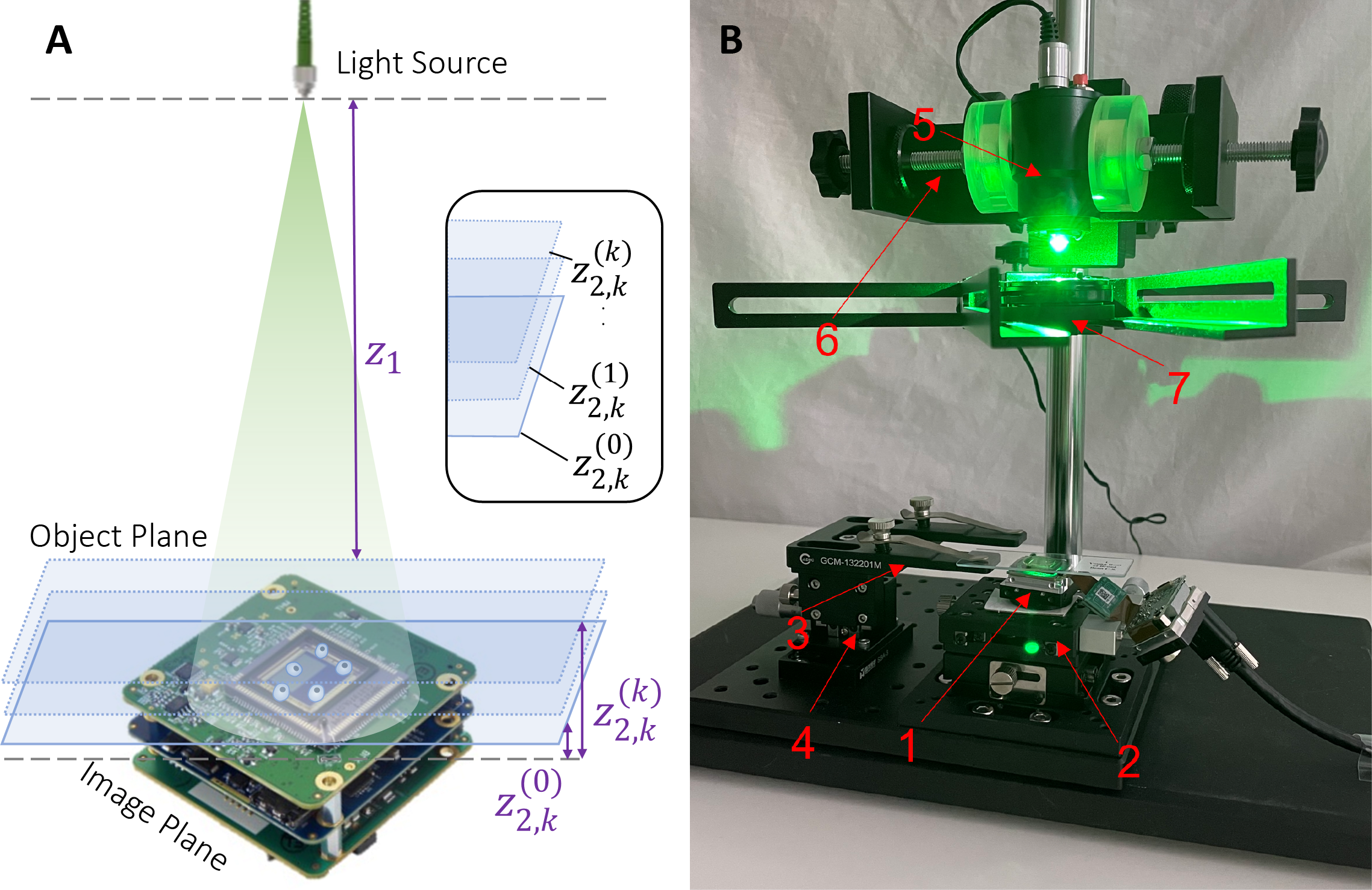
An experimental setup was developed to acquire holograms for various heights of the sample. The setup and its components are demonstrated in Figure 1: an illumination source is placed in a bench-top system above a transparent sample that is directly above the image sensor. The spacing between illumination source and the sample z2 is kept at around 10cm, while the spacing between the sample and the imaging chip z1 is kept being <1 mm. For the purpose of this paper, a 528nm green LED light is used as illumination source, a 1 mm biological glass slide is used as semi-transparent sample, and a 29 mm×29 mm complementary metal oxide semiconductor (CMOS) imaging chip with 2.4 µm×2.4 µm pixel size from The Imaging Source is used as image sensor. An optomechanical device is responsible for adjusting the sample to multiple heights.
Inside the complete setup of the microscope, one can distinguish:
(1) the CMOS camera with its USB connector;
(2) a mechanical stage that holds the camera;
(3) an optical clamp that supports the sample;
(4) an adjustable z-axis translation stage that moves the sample slide;
(5) a power-adjustable LED source;
(6) an industrial camera stand that holds the LED source;
(7) an optical pinhole to produce spherical diverging light.
It is noteworthy that LED light was chosen as illumination source instead of a laser. While LED light, unlike lasers, do not produce speckle noises due to its low temporal coherence, its low spatial coherence also reduces the interference effects on the hologram. To overcome this limitation, a small pinhole was used to increase the spatial coherence. For the particular setup,
a pinhole of diameter ≈100 µm suffices.
2.2. Theoretical principles
Based on the experimental setup described in Section 2.1, an in-line hologram is produced. As noted, the hologram records the interference of a uniformly perturbed/reference light and a uniquely perturbed/object light. In the case of the DLHM, the object is the semi-transparent cell samples, with transmittance denoted as
| |
(a) | (b) |
Figure 1. Illustrations of the optical setup. (a) Schematics of a digital holographic lensless microscope. Including an illuminating source, the sample to be imaged, and an image sensor chip. The sample plane and the image plane indicate where the sample and image sensor are located, respectively. (b) Perspective view of the experimental microscope. | |
\( σ(x, y)=σ0+∆(x, y) \) (1)
where ∆(x, y) represents the minor fluctuations in transmittance due to uniquely shaped samples, and σ0 represents the uniform transmittance along all parts of the sample plane. Note that typically ∆ σ0. Hence, the light distribution on the hologram at z0 away from the sample can be described as
\( ψ(x,y)=A[σ0+∆(x,y)]*h(x,y;{z_{0}})={ψ_{r}}+{ψ_{o}}(x,y) \) (2)
according the angular spectrum method (ASM) [17], where A represents the amplitude of incident light, ψr represents a uniform field which we will denote as reference field, ψo represents the unique field distribution sourcing from the sample which we will denote as object field, and h(x, y; z0) represents the inverse Fourier-transform of the propagation function propagating from the sample to image plane. The propagation function can be expressed as
\( H({f_{x}}, {f_{y}})=exp[i\frac{2π}{λ}z{(1-{(λ{f_{x}})^{2}}-{(λ{f_{y}})^{2}})^{\frac{1}{2}}}] \) (3)
where λ represents the wavelength of light, and fx, fy represents frequency components of incident light, respectively. Hence, the intensity/brightness recorded on the hologram can be expressed as
\( I={|{ψ_{o}}+{ψ_{r}}|^{2}}=ψ_{0}^{2}+ψ_{r}^{2}+ψ_{0}^{*}{ψ_{r}}+{ψ_{o}}ψ_{r}^{*} \) (4)
where I represents the total intensity on the hologram and \( {ψ_{o}},{ ψ_{r}} \) represents the complex light amplitude (which includes both phase and amplitude) of the object and the reference light, respectively. \( ψ_{0}^{*} \) and \( ψ_{r}^{*} \) represent the conjugate pairs of \( {ψ_{o}},{ ψ_{r}} \) , respectively. Since \( ψ_{0}^{2} \) and \( ψ_{r}^{*} \) lose their complex component, which is vital to back-solving for the object phase information, only one of \( ψ_{0}^{*}{ψ_{r}} \) or \( {ψ_{o}}ψ_{r}^{*} \) (called first-order terms) is necessary for reconstructing a 3-D profile. However, it is difficult to extract a particular desired term because all the terms overlap each other, so no separate terms can be identified. Hence, iteration based algorithms are implemented aimed at extracting the relevant object information with as much detail and as less noise as possible.
2.3. Computational implementation
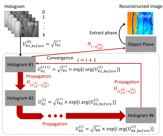
2.3.1. Phase Reconstruction. In order to identify and reconstruct one of the first order terms in the hologram, a sequence of algorithms is implemented. Initially, n number of holograms of samples at various heights are aligned onto the same domain using feature-based registration. Then, the Gerchberg-Saxton Iterative algorithm [18, 19] as shown in Figure 2 retrieves the complex amplitude of the object’s light using a several step procedure:
1.Pair a randomly generated phase distribution with the known amplitude information of the i-th hologram
2.Propagate the light distribution from the i-th hologram to the i+1-th hologram. By the angular spectrum theory [17], the propagation is given by
\( U_{\ \ \ 1}^{(i+1)}(x,y)={F^{-1}}\lbrace F[U_{\ \ \ 0}^{(i)}(x,y)]×H(z_{2,k}^{(0)},{f_{x}},{f_{y}})\rbrace \)
where \( H \) is the propagation function of the distance between the two planes and the frequency components of the Fourier transform of the i-th hologram, and ( ) is the Fourier transform operator.
3.Keep the phase information of the propagated complex light distribution and replace the amplitude with the known amplitude information of the i+1-th hologram. This produces an updated complex amplitude.
4.Repeat the process using updated phase information until all the holograms have been inputted.
5.When \( i=k \) , check if the result converges within the set sum squared error (SSE). The SSE can be defined as
\( SSE=Σ[A-A_{0}^{(k)}]/Σ{A^{2}} \)
where A represent the recorded amplitude distribution on the hologram, and A(k)
represent the calculated amplitude distribution after k iterations. If the results satisfy the condition, the iteration ends and the light is back propagated to the object plane, where the full complex amplitude of the object is obtained. If the results do not satisfy, the iteration repeats until the requirement is met.
The GS algorithm implemented in this paper has been well studied for previously in the context of digital holographic microscopy [19-21]. Seeing as the physical process behind the DLHM is similar to that of traditional DHM, the efficacy of the GS algorithm maintained its validity just as previous utilizations have [19-21].
|
Figure 2. Flowchart of the G-S algorithm, which extracts first order terms through iteration. |
2.3.2. Auto-focusing algorithm. A key aspect of implementing the multi-height based gs algorithm shown in Section 2.3.1. is considering the varying distances between sample plane and image plane. Given that the resolution of the phase reconstructed profile is highly dependent on the distance chosen, a bad estimation of distances can lead to poorly resolved image. Since the range of height adjustments are often in degrees of≈100 µm, it is impractical to perform manual measurements. Hence, an auto-focusing (AF) algorithm is incorporated to improve the performance of the gs algorithm.
For the purpose of this paper, a hill-climbing based AF algorithm is implemented to search for the most accurate distance between image and sample plane. The algorithm involves hologram reconstruction at several planes within the suspected measurement volume through pre- determined upper and lower search boundaries. Subsequently, the hologram is back propagated to the object plane to produce reconstructed image accordingly. The propagation follows the angular spectrum theory once more and is given by
\( ψ \prime (x, y)=ψ(x, y)*h(x, y; -z0) \) (5)
where \( ψ \prime \) represents the reconstructed output, ψ represents the hologram input, and h(x, y;-z0)
inverse Fourier-transform of the propagation function propagating from the image to sample plane. The propagation function is identical to that in equation 3.
A Sobel edge detecting function is utilized to examine the resolution and sharpness of the edges of each reconstructed image through contrast measures. The Sobel function can be written as
\( Sobel=\sqrt[]{{({G_{x}}·image cell)^{2}}+{({G_{y}}·image cell)^{2}}} \) (6)
where image cell represents a 3 x 3 matrix centered at an arbitrary pixel of image, and Gx, Gy, represents the horizontal and vertical Sobel kernel defined as
\( {G_{x}}=[\begin{matrix}-1 & 0 & 1 \\ -2 & 0 & 2 \\ -1 & 0 & 1 \\ \end{matrix}],{G_{y}}=[\begin{matrix}-1 & -2 & -1 \\ 0 & 0 & 0 \\ 1 & 2 & 1 \\ \end{matrix}] \) (7)
respectively.
Ultimately, the reconstruction distance at which the output exhibits a minima or maxima is considered as the object focal plane location. In order to shorten the time frame, a rough search is first implemented with larger step sizes to search for, and a finer search is followed to find the more exact distance. Ultimately, the object image evaluated at this distance is taken as the image at focus.
2.3.3. High-Resolution. After the phase information has been extracted, a bi-linear interpolation is employed to ensure good resolution of the final image.
A bi-linear interpolation can extend a grid a certain number of pixels by “guessing” new pixels using existing nearby pixels. The rationale is demonstrated in Figure 3. Given 4-pixel values, \( Q11, Q12, Q21, Q22 \) , and their respective locations, one can guess the value of an arbitrary pixel in-between by implementing linear interpolation multiple times. Assume that one guesses the value of a pixel at (x, y). The value of a point R1 is first linearly interpolated by taking the weighted average of Q11 and Q21. The linear interpolation is given by
\( f({R_{1}})=\frac{{x_{2}}-x}{{x_{2}}-{x_{1}}}f({Q_{11}})+\frac{x-{x_{1}}}{{x_{2}}-{x_{1}}}f({Q_{21}}) \)
| Figure 3. Demonstration of the bi-linear interpolation for four pixels in green. An arbitrary pixel. |
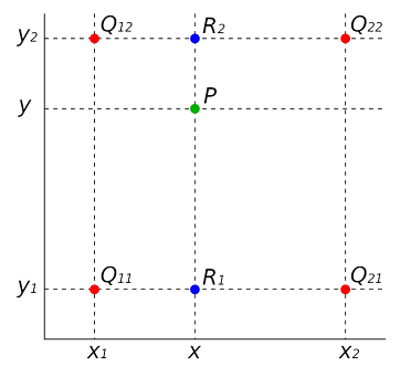
P in green is chosen. Two pixels R in blue describe how the pixel is interpolated.
where x1 and x2 are the x positions of pixels Q11 and Q21, respectively. f(·) represents the pixel value of any pixel. The same procedure can be done for R2. Next, the linear interpolation is
repeated between R1 and R2 for a given y. The result provides the pixel value of the pixel at that point. Theoretically, the method is capable of extending a picture to any resolution.
2.3.4. Phase Unwrapping and Height Reconstruction. After the phase profile of the sample is retrieved through Section 2.3.1, the 3-D information of the cell is theoretically recovered. Given that the height differences within the sample and the phase information can be easily converted through the expression
\( ϕ=\frac{2π}{λ}h \) (8)
where ϕ is the phase information, λ is the wavelength of the light, and h is the height of a particular point of the sample.
However, phase mapping can be ambiguous, as absolute phase is wrapped in the intervals [-π, π]. This results in a discontinuous imaging, as the phase signals from the points with heights that are exactly integer number of wavelengths apart are the same. A phase unwrapping process must be conducted to remove the 2π phase discontinuities in the image and estimate the true continuous phase image. Phase unwrapping consists of detecting the location of the phase jump and connecting the adjacent pixels by adding or subtracting multiples of 2π to remove the phase discontinuities.
For the purpose of this paper, a global gradient-based phase unwrapping algorithm is implemented to minimize the differences between the discrete gradients of wrapped and unwrapped phase images. Ultimately, the solved phase map with the least gradient globally is selected as the final solution. The quality measure of a phase map can be expressed as
\( J=\sum _{i=0}^{M-2} \sum _{j=0}^{N-1} {|{ϕ_{i+1,j}}-{ϕ_{i,j}}-∆_{i,j}^{x}|^{2}}+\sum _{i=0}^{M-1} \sum _{j=0}^{N-2} {|{ϕ_{i,j+1}}-{ϕ_{i,j}}-∆_{i,j}^{y}|^{2}} \) (9)
where
\( ∆_{i,j}^{x}=W({ϕ_{i+1,j}}-{ϕ_{i,j}}),∆_{i,j}^{y}=W({ϕ_{i,j+1}}-{ϕ_{i,j}}) \) (10)
where \( J \) represents the quality measure, \( M \) represents the total number of horizontal pixels of the phase map, \( N \) represents the total number of vertical pixels of the phase map, \( i \) represents the horizontal position of a particular pixel, \( j \) represents the vertical position of a particular pixel, \( ϕ \) represents the phase value of any pixel, and \( W(·) \) represents the wrapping phase operator.
After the global quality of the phase map \( J \) is measured for each variation in 2π of the pixels, a minimized \( J \) is selected with its corresponding solved for phase map profile. The absolute phase profile can hence be substituted back to Equation 8 to retrieve corresponding shapes of the cell sample.
3. Results
3.1. Auto-Focusing Calibration
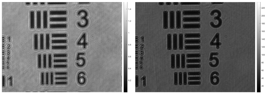
The lensless holographic microscope is first calibrated using a positive high-resolution USAF test target. The calibration process is carried out by means of the analysis of the retrieved image after numerical refocusing by angular spectrum propagation of the recorded in-line hologram. The auto-focusing algorithm theoretically determined that the focus distance is at around 24 mm, and the distance is evaluated through back propagated to verify experimental clarity. The recorded hologram is shown in Figure 4b and the back propagated image is shown in Figure 4a. The resolution of both images is at about 2.4 µm to 3 µm.
Looking at the calibration images provided by the lensless microscope, the back propagated images are especially resolved at the 24 mm focus distance expected. The patterns on the leftside of the image had significant improvement in terms of contrast and detail, surrounded with few concentric rings of dark and bright fringes due to interference.
| |
(a) | (b) |
Figure 4. Demonstration of auto-focusing process calibrated to high-resolution USAF test targets. (a) Shows the focused image that is derived from; (b) the original unfocused hologram. | |
3.2. Static Biosamples Inspection
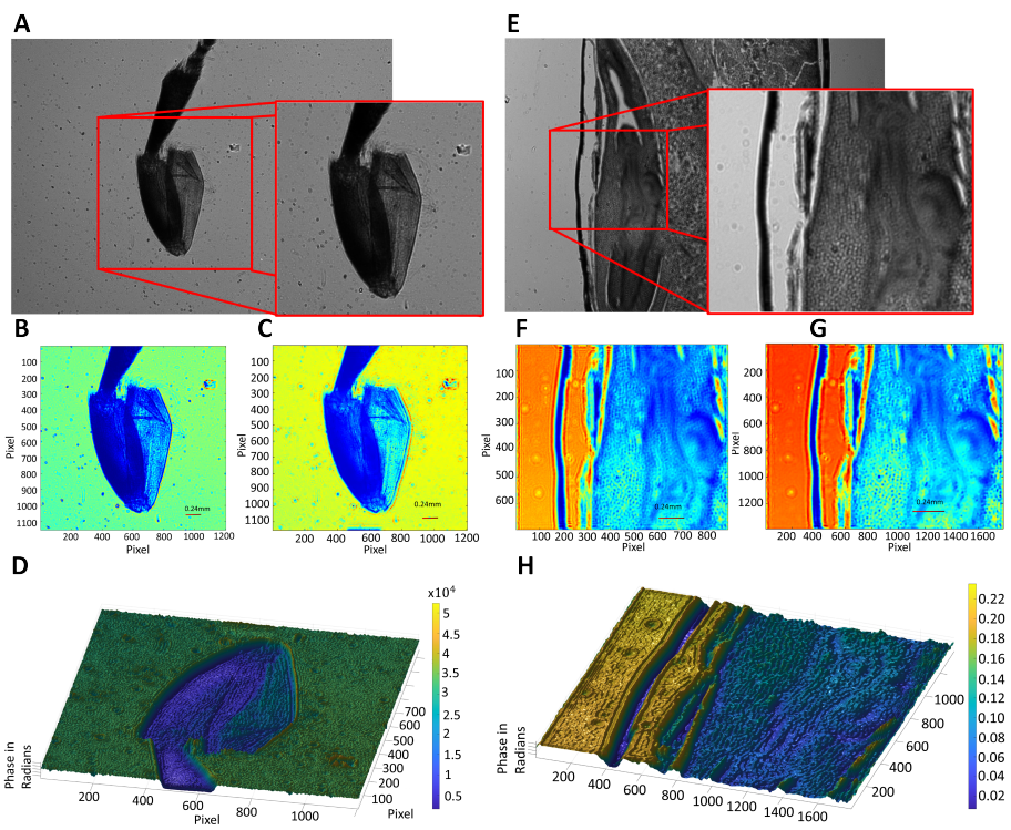
The lensless holographic microscope is utilized for imaging several fixed and undyed biosamples. More concretely, the biosamples are honeybee foreleg in Figure 5a-d, and zea seed in Figure 5e-h. The holograms retrieved by the lensless microscope is included in Figure 5a, d. The phase image retrieved based on single height is included in Figure 5b, f. The phase image retrieved based on multiple height is included in Figure 5c, g. The ultimate 3-D reconstruction of phase profile of the sample based on multiple heights is shown in Fig. 5d,h. The hologram size of the configuration is 2048×3072 pixels with each pixel size of 2.4 µm . The full area of the hologram is 36.2 mm2.The selected proportion of the honeybee foreleg hologram has an area of 8 mm2. The selected proportion of the zea seed hologram has an area of 3.6 mm2.
Looking at the images provided by the lensless microscope, the 3-D shape of the cellular types are easily visible, though there are some fluctuations due to rough surfaces and other noise sources. There are less distinctive 3-D shape then as expected because a non-living, compressed sample was used for this study. Moreover, due to the inherent properties of the lensless holographic microscope, some internal structures within semi-transparent samples are also recorded.
4. Discussion
4.1. Auto-focusing calibration
In order to reconstruct the hologram retrieved using digital lensless holographic microscope, and auto-focusing algorithm was implemented to find the exact focus distance as outlined in Section 2.3.2. The results shown in Section 3.1 indeed demonstrated that an exact focus distance is found, which was similar to results from previous literature [22]. Similarly, the back propagated images both showed higher contrast, more distinguishable patterns, finer details, and less blurriness. Both the results from this paper and that of Picazo-Bueno’s [22] shown reduced but still apparent concentric circles of dark and light fringes around patterns. This is likely due to interference result that arises from propagation inevitably, which can be reduced through the following gs algorithms which extracts terms through iteration. While there has been previous literatures [23, 24] that also examines the auto-focusing algorithm, most lack practicality in efficiency and even few is applied in the DLHM. The results of this paper verify that the presented auto-focusing algorithm can be applied extensively in the field of holographic microscopes to determine focus- distance in an efficient manner.
|
Figure 5. Inspection of different static and unlabeled biosamples. Row 1 include the images for honeybee foreleg while row 2 include the images for zea seed. (a) and (e) Full hologram and zoomed-in proportions for honeybee foreleg and zea seed, respectively. (b) and (f) Unwrapped phase images retrieved from single height for honeybee foreleg and zea seed, respectively. (c) and (g) Unwrapped phase image retrieved from multiple heights for honeybee foreleg and zea seed, respectively. (d) and (h) 3-D representation of reconstructed phase map for honeybee foreleg and zeaseed, respectively. |
4.2. Static biosamples inspection
The 3-D bio-inspection of honeybee foreleg and zea seed samples demonstrated that the presented DLHM is able to obtain 3-D cell images with fine quality. Compared to existing microscopy techniques, the DLHM holds several advantages. Firstly, the results in Section 3.2 demonstrated that the DLHM is capable of recording images with a lateral resolution of up to 2.4 µm-1.7 µm (depending on the interpolation used for boosting resolution) without the use of any lens for imaging. The resolution is similar to that of Picazo-Bueno’s work [22] (with a lateral resolution of 1.65 µm). Given that typical optical microscopes have a resolution of a couple hundred nano- meters, the DLHM is approaching but still lacking good resolution. Given that an important limitation of the lensless holographic microscope resolution is created by the pixel size of the sensor, future work concerning the improvement of DLHM’s resolution can either focus on lowering the physical pixel sizes of image sensors or image processing techniques (such as pixel super-resolution algorithms [25]). Secondly, the resulting hologram can reach a large field of view. While conventional microscopes can only reach a field of 2-16 mm2, the DLHM recorded a hologram size of 36.2 mm2 in Section 3.2 that is about 2-20 times bigger than conventional FOV. Moreover, since the DLHM removes the tradeoff between resolution and FOV, it can actually record a much larger FOV at the same resolution with traditional microscopes. For future research, the FOV can actually be much larger than the ones presented in this work, since the FOV of DLHM is only limited essentially to the size of the image sensor. Thus, the DLHM is still capable of recording holograms that is tens to hundreds times of the images in Section 3.2 if a large enough CCD or CMOS is designed. Lastly, the current DLHM costs at about $500-$600 mostly due to production costs of LED, image sensors, and supporting structures. Compared to conventional digital microscopes, the DLHM is extremely cost effective with almost one-tenth of the cost. The portability, compactness, and low-cost of the DLHM is still greatly limited in this study due to inability of using 3-D printing machines. Ideally, the DLHM should be able to weight at around 500g and cost less than $200, as demonstrated in previous literatures [22, 26, 27].
5. Conclusion
This paper investigates the 3-D recording and reconstruction of cell samples through the implementation of a digital lensless holographic microscope. First, an optical path design of the microscope is shown such that a good quality hologram can be obtained for further extracting and processing. Next, an auto-focusing algorithm was utilized to calculate the focus distance. The focus distance will then be inputted as a parameter into the gs algorithm, where the phase information of the sample is extracted through iteration. After image processing techniques such as interpolation and unwrapping, a 3-D image of the cell sample is ultimately produced and demonstrated in Section 3. The results show that the DLHM technique adopted in this study provides a high-resolution, large FOV, label-free, 3-D imaging of cell samples. Comparing with conventional microscopes, the DLHM is able to reach a FOV almost 20 times larger, and a comparable resolution of 1.7 µm. Moreover, the current DLHM costs at about $500-$600, greatly reducing the production costs of such microscopes compared to others. For POCTs with limited medical sources that require immediate accurate inspection of cells, accessibility, and low-cost, the DLHM can hold great promises for future commercialization. The experimentation of DLHM in this paper may serve as a verification and basis for future improvements, through which DLHM can be made technologically mature enough to put into practice. However, some limitations in this paper include the relatively bulky and costly design of the microscope, the resolution. Although the optical design of the microscopes is already much lower than conventional microscopes, previous literatures have demonstrated that the use of 3-D printed microscopes can greatly reduce the complexity and cost of the design, which will likely be the source of firmware productions of DLHM in the future. Moreover, the DLHM is still limited in terms of its resolution as it is dependent on the pixel size of the image sensor. Current research has been focusing on sub pixel super-resolution algorithms which is capable of surpassing industrial limitations and enhance the resolution by a couple multiples. Similarly, an interpolation method is implemented in this study to improve partially the resolution of the phase map.
References
[1]. Sarkar D, Kang J, Wassie A T, Schroeder M E, Peng Z, Tarr T B, Tang A H, Niederst E D, Young J Z, Su H, Park D, Yin P, Tsai L H, Blanpied T A and Boyden E S 2022 Nature Biomedical Engineering 6 1057–1073 ISSN 2157-846X number: 9 Publisher: Nature Publishing Group URL https://www.nature. com/articles/s41551-022-00912-3
[2]. Wang J, Han M, Roy A R, Wang H, Möckl L, Zeng L, Moerner W E and Qi L S 2022 Cell Reports Methods 2 100170 ISSN 2667-2375 URL https://www.sciencedirect. com/science/article/ pii/S2667237522000224
[3]. Carlsson K, Danielsson P E, Lenz R, Liljeborg A, Majlöf L and Åslund N 1985 Optics Letters 10 53–55 ISSN 1539-4794 publisher: Optica Publishing Group URL https://opg.optica. org/ol/abstract.cfm? uri=ol-10-2-53
[4]. Voronin Y M, Didenko I A and Chentsov Y V 2006 Journal of Optical Technology 73 101–110 publisher: S.I.Vavilov Optical Institute URL https://opg.optica.org/jot/abstract.cfm?uri=jot-73-2-101
[5]. Yanny K, Antipa N, Liberti W, Dehaeck S, Monakhova K, Liu F L, Shen K, Ng R and Waller L 2020 Light: Science & Applications 9 171 ISSN 2047-7538 number: 1 Publisher: Nature Publishing Group URL https://www.nature.com/articles/s41377-020-00403-7
[6]. Huang T 1971 Proceedings of the IEEE 59 1335–1346 ISSN 1558-2256 conference Name: Proceedings of the IEEE
[7]. Greenbaum A, Zhang Y, Feizi A, Chung P L, Luo W, Kandukuri S R and Ozcan A 2014 Science Translational Medicine 6 267ra175 ISSN 1946-6242
[8]. Zhang Y, Greenbaum A, Luo W and Ozcan A 2015 Virchows Archiv 467 3–7 ISSN 1432-2307 URL https://doi.org/10.1007/s00428-015-1782-z
[9]. Zhang Y, Lee S Y C, Zhang Y, Furst D, Fitzgerald J and Ozcan A 2016 Scientific Reports 6 28793 ISSN 2045-2322 number: 1 Publisher: Nature Publishing Group URL https://www.nature. com/articles/ srep28793
[10]. Isikman S O, Sencan I, Mudanyali O, Bishara W, Oztoprak C and Ozcan A 2010 Lab on a chip 10 1109–1112 ISSN 1473-0197 URL https://www.ncbi.nlm.nih.gov/pmc/articles/ PMC2869489/
[11]. Isikman S O, Bishara W, Zhu H and Ozcan A 2011 Applied Physics Letters 98 161109 ISSN 0003-6951 publisher: American Institute of Physics URL https://aip.scitation.org/doi/ 10.1063/1.3548564
[12]. Mudanyali O, Oztoprak C, Tseng D, Erlinger A and Ozcan A 2010 Lab on a Chip 10 2419–2423 ISSN 1473-0189 publisher: The Royal Society of Chemistry URL https://pubs.rsc.org/en/content/ articlelanding/2010/lc/c004829a
[13]. Feizi A, Zhang Y, Greenbaum A, Guziak A, Luong M, Chan R Y L, Berg B, Ozkan H, Luo W, Wu M, Wu Y and Ozcan A 2016 Lab on a Chip 16 4350–4358 ISSN 1473-0189 publisher: The Royal Society of Chemistry URL https://pubs.rsc.org/en/content/articlelanding/2016/lc/ c6lc00976j
[14]. Su T W, Erlinger A, Tseng D and Ozcan A 2010 Analytical Chemistry 82 8307–8312 ISSN 1520-6882
[15]. Su T W, Xue L and Ozcan A 2012 Proceedings of the National Academy of Sciences 109 16018–16022 publisher: Proceedings of the National Academy of Sciences URL https://www.pnas.org/doi/10.1073/ pnas.1212506109
[16]. Su T W, Choi I, Feng J, Huang K, McLeod E and Ozcan A 2013 Scientific Reports 3 1664 ISSN 2045-2322 number: 1 Publisher: Nature Publishing Group URL https://www.nature.com/articles/srep01664
[17]. Goodman J W 2005 Introduction to Fourier Optics (Roberts and Company Publishers) ISBN 0-9747077-2-4 978-0-9747077-2-3
[18]. Gerchberg R W 1972 Optik 35 237–246 URL https://api.semanticscholar.org/CorpusID: 55691159
[19]. Jiang Y, Li H, Pang Y, Ling J, Wang H, Yang Y, Li X, Tian Y and Wang X 2022 Frontiers in Physiology 13 ISSN 1664-042X URL https://www.frontiersin.org/articles/10.3389/fphys. 2022.1040777
[20]. Madsen A E G, Panah M A, Larsen P E, Nielsen F and Glückstad J 2023 Optics Communications 537 129458 ISSN 0030-4018 URL https://www.sciencedirect.com/science/article/pii/ S0030401823002055
[21]. Cruz M L, Castro A and Arrizón V 2008 Optics and Photonics for Information Processing II vol 7072 (SPIE) pp 330–339 URL https://www.spiedigitallibrary.org/conference-proceedings-of-spie/ 7072/70721C/Phase-retrieval-in-digital-holographic-microscopy-using-a-Gerchberg-Saxton/ 10.1117/12.793894.full
[22]. Picazo-Bueno J A, Trindade K, Sanz M and Micó V 2022 Sensors 22 553 ISSN 1424-8220 number: 2 Publisher: Multidisciplinary Digital Publishing Institute URL https://www.mdpi.com/1424-8220/22/2/ 553
[23]. Firestone L, Cook K, Culp K, Talsania N and Preston Jr K 1991 Cytometry 12 195–206 ISSN 1097-0320_eprint: https://onlinelibrary.wiley.com/doi/pdf/10.1002/cyto.990120302 URL https://onlinelibrary. wiley.com/doi/abs/10.1002/cyto.990120302
[24]. Groen F C A, Young I T and Ligthart G 1985 Cytometry 6 81–91 ISSN 1097-0320 _eprint:https://onlinelibrary.wiley.com/doi/pdf/10.1002/cyto.990060202 URL https:// onlinelibrary. wiley. com/doi/abs/10.1002/cyto.990060202
[25]. Sobieranski A C, Inci F, Tekin H C, Yuksekkaya M, Comunello E, Cobra D, von Wangenheim A and Demirci U 2015 Light: Science & Applications 4 e346–e346 ISSN 2047-7538 number: 10 Publisher: Nature Publishing Group URL https://www.nature.com/articles/lsa2015119
[26]. Tobon-Maya H, Zapata-Valencia S, Zora-Guzmán E, Buitrago-Duque C and Garcia-Sucerquia J 2021 Applied Optics 60 A205–A214 ISSN 2155-3165 publisher: Optica Publishing Group URL https://opg.optica. org/ao/abstract.cfm?uri=ao-60-4-A205
[27]. Amann S, Witzleben M v and Breuer S 2019 Scientific Reports 9 11260 ISSN 2045-2322 number: 1 Publisher: Nature Publishing Group URL https://www.nature.com/articles/s41598-019-47689-1
Cite this article
Yang,T.Z.;Wu,Y. (2023). Seeing cells without a lens: Compact 3D digital lensless holographic microscopy for wide-field imaging. Theoretical and Natural Science,12,61-72.
Data availability
The datasets used and/or analyzed during the current study will be available from the authors upon reasonable request.
Disclaimer/Publisher's Note
The statements, opinions and data contained in all publications are solely those of the individual author(s) and contributor(s) and not of EWA Publishing and/or the editor(s). EWA Publishing and/or the editor(s) disclaim responsibility for any injury to people or property resulting from any ideas, methods, instructions or products referred to in the content.
About volume
Volume title: Proceedings of the 2023 International Conference on Mathematical Physics and Computational Simulation
© 2024 by the author(s). Licensee EWA Publishing, Oxford, UK. This article is an open access article distributed under the terms and
conditions of the Creative Commons Attribution (CC BY) license. Authors who
publish this series agree to the following terms:
1. Authors retain copyright and grant the series right of first publication with the work simultaneously licensed under a Creative Commons
Attribution License that allows others to share the work with an acknowledgment of the work's authorship and initial publication in this
series.
2. Authors are able to enter into separate, additional contractual arrangements for the non-exclusive distribution of the series's published
version of the work (e.g., post it to an institutional repository or publish it in a book), with an acknowledgment of its initial
publication in this series.
3. Authors are permitted and encouraged to post their work online (e.g., in institutional repositories or on their website) prior to and
during the submission process, as it can lead to productive exchanges, as well as earlier and greater citation of published work (See
Open access policy for details).
References
[1]. Sarkar D, Kang J, Wassie A T, Schroeder M E, Peng Z, Tarr T B, Tang A H, Niederst E D, Young J Z, Su H, Park D, Yin P, Tsai L H, Blanpied T A and Boyden E S 2022 Nature Biomedical Engineering 6 1057–1073 ISSN 2157-846X number: 9 Publisher: Nature Publishing Group URL https://www.nature. com/articles/s41551-022-00912-3
[2]. Wang J, Han M, Roy A R, Wang H, Möckl L, Zeng L, Moerner W E and Qi L S 2022 Cell Reports Methods 2 100170 ISSN 2667-2375 URL https://www.sciencedirect. com/science/article/ pii/S2667237522000224
[3]. Carlsson K, Danielsson P E, Lenz R, Liljeborg A, Majlöf L and Åslund N 1985 Optics Letters 10 53–55 ISSN 1539-4794 publisher: Optica Publishing Group URL https://opg.optica. org/ol/abstract.cfm? uri=ol-10-2-53
[4]. Voronin Y M, Didenko I A and Chentsov Y V 2006 Journal of Optical Technology 73 101–110 publisher: S.I.Vavilov Optical Institute URL https://opg.optica.org/jot/abstract.cfm?uri=jot-73-2-101
[5]. Yanny K, Antipa N, Liberti W, Dehaeck S, Monakhova K, Liu F L, Shen K, Ng R and Waller L 2020 Light: Science & Applications 9 171 ISSN 2047-7538 number: 1 Publisher: Nature Publishing Group URL https://www.nature.com/articles/s41377-020-00403-7
[6]. Huang T 1971 Proceedings of the IEEE 59 1335–1346 ISSN 1558-2256 conference Name: Proceedings of the IEEE
[7]. Greenbaum A, Zhang Y, Feizi A, Chung P L, Luo W, Kandukuri S R and Ozcan A 2014 Science Translational Medicine 6 267ra175 ISSN 1946-6242
[8]. Zhang Y, Greenbaum A, Luo W and Ozcan A 2015 Virchows Archiv 467 3–7 ISSN 1432-2307 URL https://doi.org/10.1007/s00428-015-1782-z
[9]. Zhang Y, Lee S Y C, Zhang Y, Furst D, Fitzgerald J and Ozcan A 2016 Scientific Reports 6 28793 ISSN 2045-2322 number: 1 Publisher: Nature Publishing Group URL https://www.nature. com/articles/ srep28793
[10]. Isikman S O, Sencan I, Mudanyali O, Bishara W, Oztoprak C and Ozcan A 2010 Lab on a chip 10 1109–1112 ISSN 1473-0197 URL https://www.ncbi.nlm.nih.gov/pmc/articles/ PMC2869489/
[11]. Isikman S O, Bishara W, Zhu H and Ozcan A 2011 Applied Physics Letters 98 161109 ISSN 0003-6951 publisher: American Institute of Physics URL https://aip.scitation.org/doi/ 10.1063/1.3548564
[12]. Mudanyali O, Oztoprak C, Tseng D, Erlinger A and Ozcan A 2010 Lab on a Chip 10 2419–2423 ISSN 1473-0189 publisher: The Royal Society of Chemistry URL https://pubs.rsc.org/en/content/ articlelanding/2010/lc/c004829a
[13]. Feizi A, Zhang Y, Greenbaum A, Guziak A, Luong M, Chan R Y L, Berg B, Ozkan H, Luo W, Wu M, Wu Y and Ozcan A 2016 Lab on a Chip 16 4350–4358 ISSN 1473-0189 publisher: The Royal Society of Chemistry URL https://pubs.rsc.org/en/content/articlelanding/2016/lc/ c6lc00976j
[14]. Su T W, Erlinger A, Tseng D and Ozcan A 2010 Analytical Chemistry 82 8307–8312 ISSN 1520-6882
[15]. Su T W, Xue L and Ozcan A 2012 Proceedings of the National Academy of Sciences 109 16018–16022 publisher: Proceedings of the National Academy of Sciences URL https://www.pnas.org/doi/10.1073/ pnas.1212506109
[16]. Su T W, Choi I, Feng J, Huang K, McLeod E and Ozcan A 2013 Scientific Reports 3 1664 ISSN 2045-2322 number: 1 Publisher: Nature Publishing Group URL https://www.nature.com/articles/srep01664
[17]. Goodman J W 2005 Introduction to Fourier Optics (Roberts and Company Publishers) ISBN 0-9747077-2-4 978-0-9747077-2-3
[18]. Gerchberg R W 1972 Optik 35 237–246 URL https://api.semanticscholar.org/CorpusID: 55691159
[19]. Jiang Y, Li H, Pang Y, Ling J, Wang H, Yang Y, Li X, Tian Y and Wang X 2022 Frontiers in Physiology 13 ISSN 1664-042X URL https://www.frontiersin.org/articles/10.3389/fphys. 2022.1040777
[20]. Madsen A E G, Panah M A, Larsen P E, Nielsen F and Glückstad J 2023 Optics Communications 537 129458 ISSN 0030-4018 URL https://www.sciencedirect.com/science/article/pii/ S0030401823002055
[21]. Cruz M L, Castro A and Arrizón V 2008 Optics and Photonics for Information Processing II vol 7072 (SPIE) pp 330–339 URL https://www.spiedigitallibrary.org/conference-proceedings-of-spie/ 7072/70721C/Phase-retrieval-in-digital-holographic-microscopy-using-a-Gerchberg-Saxton/ 10.1117/12.793894.full
[22]. Picazo-Bueno J A, Trindade K, Sanz M and Micó V 2022 Sensors 22 553 ISSN 1424-8220 number: 2 Publisher: Multidisciplinary Digital Publishing Institute URL https://www.mdpi.com/1424-8220/22/2/ 553
[23]. Firestone L, Cook K, Culp K, Talsania N and Preston Jr K 1991 Cytometry 12 195–206 ISSN 1097-0320_eprint: https://onlinelibrary.wiley.com/doi/pdf/10.1002/cyto.990120302 URL https://onlinelibrary. wiley.com/doi/abs/10.1002/cyto.990120302
[24]. Groen F C A, Young I T and Ligthart G 1985 Cytometry 6 81–91 ISSN 1097-0320 _eprint:https://onlinelibrary.wiley.com/doi/pdf/10.1002/cyto.990060202 URL https:// onlinelibrary. wiley. com/doi/abs/10.1002/cyto.990060202
[25]. Sobieranski A C, Inci F, Tekin H C, Yuksekkaya M, Comunello E, Cobra D, von Wangenheim A and Demirci U 2015 Light: Science & Applications 4 e346–e346 ISSN 2047-7538 number: 10 Publisher: Nature Publishing Group URL https://www.nature.com/articles/lsa2015119
[26]. Tobon-Maya H, Zapata-Valencia S, Zora-Guzmán E, Buitrago-Duque C and Garcia-Sucerquia J 2021 Applied Optics 60 A205–A214 ISSN 2155-3165 publisher: Optica Publishing Group URL https://opg.optica. org/ao/abstract.cfm?uri=ao-60-4-A205
[27]. Amann S, Witzleben M v and Breuer S 2019 Scientific Reports 9 11260 ISSN 2045-2322 number: 1 Publisher: Nature Publishing Group URL https://www.nature.com/articles/s41598-019-47689-1