


1. Introduction
In recent years, solar power plants have attracted much attention worldwide. While people continually focus on environmental issues and renewable energy, solar power plants are vital to the clean energy transition. Solar power plants use solar energy as the main source, converting solar radiation into electricity via photovoltaic conversion. One of its greatest advantages is its renewable function, as solar energy is an endless source of energy that provides a continuous supply of electricity without producing greenhouse gas emissions and environmental pollution [1]. Solar power plants produce less carbon and are more environmentally friendly than fossil fuels. Otherwise, solar power plants can be separated, maximize the sunshine resource, reduce the reliance on transportation and distribution, and increase the reliability of supplements. The Dish engine stands out as a special technology among the many types of solar power plants available today [2]. A dish engine is a heat engine based on the Stirling cycle, which converts the heat of solar radiation into mechanical energy and electricity. The system comprises a parabolic dish with a reflector and a Stirling engine located at the dish's focal point. The sun’s rays are focused by the dish, which heats the medium gases and drives the engine. The dish engine is used a lot in solar power generation by its low maintenance cost, high reliability and efficiency. It also can be used in small domestic applications, such as power and heating.
The Stirling engine is an important part of the dish engine, a heat engine that utilizes temperature differences to cause gas circulation. The Alpha Stirling engine is a Stirling engine and a common model designed with a regenerator that connects the hot cylinder with the cold one. The pistons of the two cylinders are 90 degrees out of phase, enabling continuous gas flow. The second is the Beta Stirling engine, which has only one power piston and a heat exchanger, with a displacement piston for regulating the working gas flow. This variant is simpler and commonly used in small applications. Finally, there is the Gamma Stirling engine, which consists of power and displacement cylinders connected by a common piston rod. The power piston works in the power cylinder, while the displacement piston moves in the displacement cylinder. Various variants and modifications are possible depending on the specific needs and applications. The Alpha engine, which is widely used, has a high theoretical thermal efficiency, but in practice, the whole system's efficiency is much reduced due to heat loss. Improving the system’s thermal efficiency by improving the regenerator is important.
2. Fundamentals of alpha solar stirling engines
2.1. Components and working cycle
The Alpha Stirling engine is a common conventional Stirling engine [3]. Hot and cold cylinders form it, while a regenerator is between them. Two pistons are connected with one crankshaft at 90 degrees (Figure 1). The hot cylinder is heated by sunlight or other heat sources to expand the medium gas (usually helium or hydrogen). This expansion pushes the piston, producing mechanical work [4].
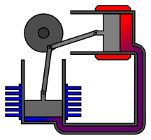
Figure 1. Stirling engines working principle, reproduced from website: https://en.wikipedia.org/wiki/Stirling_engine
Next, the working gas is transferred to the cold cylinder for cooling. As the piston moves through the cold cylinder, it compresses the gas medium and transfers it to the hot side. In this way, the Alpha Stirling engine continuously converts energy by the medium gas medium, alternately making a round trip between the hot and cold cylinders.
To better understand how the Alpha Stirling engine works, we can refer to typical processes illustrated in the T-S and P-V diagrams (Figure 2): isochoric heating, isothermal expansion, isochoric cooling and isothermal compression.
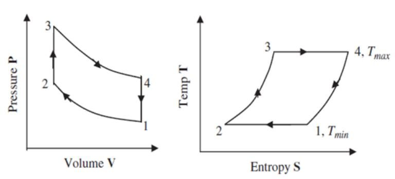
Figure 2. Thermal cycle diagram of Stirling engine, reproduced from website: https://www.researchgate.net/figure/P-V-and-T-S-diagram-for-Stirling-engine_fig1_349138276
The first process is compression, where the gas medium is further compressed in the cold tank and then returned to the hot tank. The temperature is the lowest \( {T_{min}} \) . Next comes the heating process, where a heat source heats the gas in the hot cylinder. In this process, the medium gas absorbs the heat and then expands, pushing the piston. During the expansion process, the gas medium propels the piston from the hot cylinder to the cold cylinder. The gas medium is then cooled in the cold cylinder, causing a reduction in volume. The temperature comes at the highest \( {T_{max}} \) . Finally, the gas medium absorbs heat from the cold cylinder during the cooling process. The temperature is down to the lowest \( {T_{min}} \) .
2.2. Efficiency and heat loss
According to understanding the Alpha Stirling engine's basic principle and working cycle, we can notice that the Alpha Stirling engine has a high theoretical efficiency compared to conventional internal combustion engines [5]. There are several reasons why the Stirling engine is able to achieve high theoretical efficiency. Firstly and mainly, the Carnot equation proves the efficiency, which is an ideal cycle with the max thermal efficiency [6].
\( η=1-\frac{{T_{max}}}{{T_{min}}} \) (1)
Compared with the traditional engine, the Stirling engine uses isothermal expansion and compression in the cycle rather than the combustion process. This means the Stirling engine uses heat to avoid heat loss from combustion, achieving a higher theoretical efficiency. At the same time, low heat loss is vital for high efficiency. Stirling engines work with no combustion and explosion processes, so the heat loss is relatively low. The medium gas undergoes energy conversion rather than combustion. This reduces heat loss and increases the efficiency of heat energy usage.
However, while the Alpha Stirling engine has a high potential for efficiency, it is essential to note that there are still some important considerations to consider. Practical efficiency is still at a low level nowadays. It is influenced by many factors, such as the temperature gap between cold and hot cylinders, internal heat loss, cooling loss, etc. [7]. Of all the losses, the cooling loss is the most significant. When a Stirling engine is cooling, the medium gas must be transferred from the hot cylinder to the cold and heated again. Cooling the reheating process results in energy loss and reduced thermal efficiency. Although the regenerator in the engine can recover and utilize some of the heat, there is still some loss caused by the regenerator.
In a Stirling engine, the cooling loss is in two main ways. Firstly, when the medium gas is transferred between two cylinders, there is a heat transfer process where some of the heat energy is transferred through the walls into the environment. This heat transfer results in a loss of energy and reduced efficiency. But the most important thing is that the regenerator attracts heat from the gas in the hot gas cylinder when in contact with the cylinder and cannot reheat the return gas. This part of the heat energy of the working gas is lost in the form of cooling and cannot be converted into mechanical work, which significantly lowers the efficiency.
3. Regenerator in the alpha stirling engine
3.1. Working principle
The Alpha Stirling engine is a heat engine that generates power by converting thermal energy into mechanical energy. In this type of engine, the regenerator plays a key role. The regenerator (Figure 3) is the heat exchanger in the engine, and its function is to store and reuse thermal energy during the gas cycle [8]. It consists of metal or ceramic materials with a high heat capacity, usually in a grid or honeycomb structure.
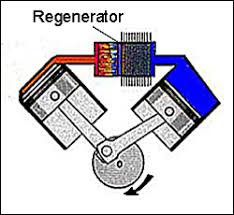
Figure 3. The regenerator of the Stirling engine, obtained from the website: http://solarcellcentral.com/stirling_page.html
The regenerator mainly functions in expansion and compression processes [9-11]. The gas is heated and pushed to the cold cylinder, where the regenerator absorbs and stores heat energy. The thermal energy is transferred to the materials inside the regenerator, raising its temperature rather than releasing this heat completely outside the system. These materials include metals or ceramics with high specific heat capacity, such as copper, steel wire and ceramic fibers. The greater the specific heat capacity, the more heat can be absorbed and stored. However, the gas is pushed to return to the hot cylinder during compression. At this time, the regenerator releases the previously stored thermal energy. As the return gas passes through the regenerator, the material inside it transfers its thermal energy, raising its temperature. In this way, the regenerator allows the gas to be reheated, reducing the heat absorbed in the hot cylinder and increasing the engine’s efficiency.
3.2. The structure and material
The most common regenerator designs are cylindrical or ring-shaped. Stirling engines with a cylindrical regenerator can be equipped with multiple regenerators simultaneously. In contrast, Stirling engines with a ring regenerator usually have the regenerator wrapped around the engine's piston. Regenerators are available in a variety of configurations and materials. The following are two common cylindrical regenerator configurations and materials used today. Copper foam regenerator (Figure 4): copper foam is a type of porous media with high porosity [12]. Because of the higher permeability compared to other media, the working gas in the copper foam could be more uniform during its flowing. This way makes the energy transportation between solid and gas more efficient. A better effective thermal conductivity and smaller pressure drop could shorten the period of the heat absorbed from the working gas. However, a lower heat capacity means this type of regenerator stores less heat than the stainless-steel type.
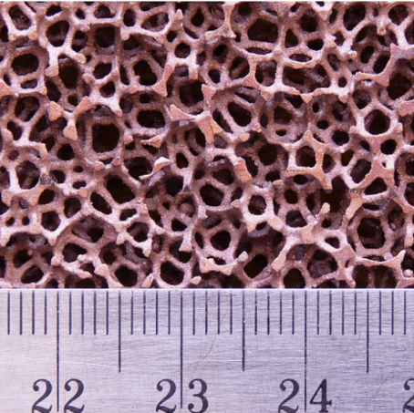
Figure 4. Copper foam [13].
Stainless-steel mesh regenerator (Figure 5): This type is made of multiple layers of stainless-steel mesh and is widely used today in the solar industry in solar dish engines [14]. The multi-layer mesh made of stainless steel is not only not prone to oxidation but also has a high specific heat capacity, which makes the engine produce a larger output. However, the interweaving of the steel nets produces high-flow friction. Meanwhile, there is a randomness in the stacking of the meshes, which could cause localized flowing problems, lower the flow rate of the gases and greater flow resistance losses in the regenerator.
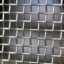
Figure 5. Stainless-steel net, obtained from the website:
https://www.mechero.my/post/wire-mesh-types-application
3.3. Optimization of the regenerator
Both of these regenerators have their special advantages and disadvantages. Choosing one of them in the practical industry does not significantly improve thermal efficiency [15,16]. Due to the large temperature difference between the hot and cold sites, the axial temperature and pressure distribution in the porous area cannot be uniform, and the use of only a single material for the regenerator can lead to significant heat loss [17]. Based on different material properties, the hot side is filled with copper foam with low thermal conductivity, and the stainless steel is filled with the cold side with a low thermal conductivity and high heat storage index. This design allows the hot working gas to be absorbed quickly and the heat to be released slowly at the cold side. As a result, the capacity to absorb and store heat is increased. This special design is theoretically effective in reducing heat losses and increasing efficiency, significantly increasing overall performance. A simulation experiment is set up with various regenerator forms to verify that this special regenerator can hugely improve thermal efficiency.
4. Experiment
4.1. Software introduction
Because of the small size of the regenerator, it is not easy to install temperature sensors for real-world experiments. So this experiment will use FLUENT simulation software (Figure 6), version 2021R1, a widely used CFD software for simulating and analyzing complex mass flows [18].

Figure 6. Ansys software (Photo/Picture credit: Original).
4.2. Parameter setting
The simplified cylindrical regenerator model is set to be 100 mm long and 50mm in diameter, and a mesh model is generated with a single element size of 0.01. As temperature analysis is included, the energy equation switch must be turned on at the General option, and the turbulence solution mode needs to be set in Realizable K-epsilon. The flow rate is set at 0.05 kg/s, and the temperature at 700 °C. The left-hand outlet of the regenerator is set as outflow, with free flow out and no temperature setting. The cylinder boundary of the regenerator is isothermal, with a roughness constant of 0.5 and a roughness height of 0.5 mm. The interior of the regenerator is a porous medium through which air flows. To allow for a more significant difference in the resultant data for different materials, a lower porosity is set, the lowest value of 70% of the range commonly used in the industry where the viscous resistance and internal resistance in porous media need to be further calculated and set.
The vicious and internal resistance is related to the diameter size of the material particles \( {D_{p}} \) and the porosity \( n \) of the filling material. According to the relevant empirical equations, the viscous resistance and internal resistance of the material in the porous media region in the regenerator are calculated as follows [19-21]:
\( α=\frac{{D^{2}}}{150}\frac{{ε^{3}}}{(1-ε{)^{2}}} \) (2)
\( {C_{2}}=\frac{3.5}{{D_{p}}}\frac{(1-ε)}{{ε^{3}}} \) (3)
In the software simulation, the air as working gas moves in the axial z-direction in the porous media area, so the resistance in the radial direction should be defined as one thousand times the axial value, which is considered to be an infinite resistance of the working gas in the radial direction. The detailed setup parameters are shown in Figure 8.
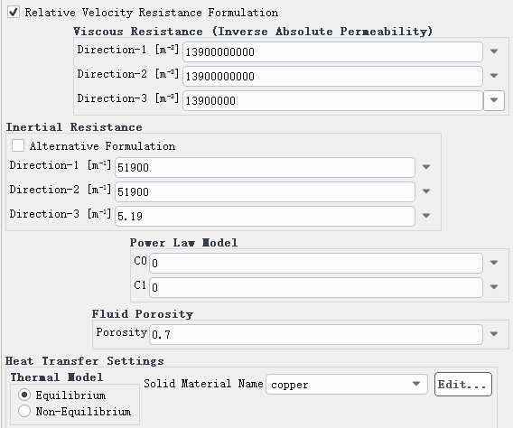
Figure 7. Porous area setting (Photo/Picture credit: Original).
4.3. Comparison of experimental results
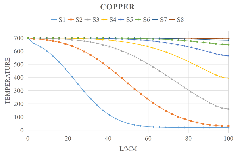
Figure 8. Copper foam regenerator temperature distribution (Photo/Picture credit: Original).
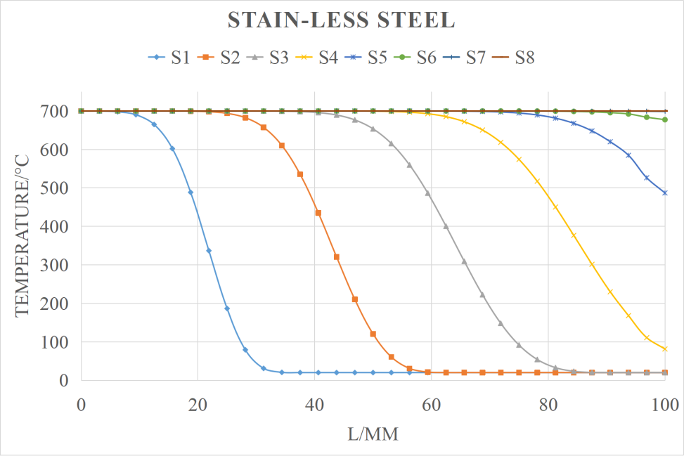
Figure 9. Stainless steel net regenerator temperature distribution (Photo/Picture credit: Original).
Comparing Figure 8. and Figure 9., it can be concluded that the regenerator is mainly convective heat exchange under the working condition of 70% porosity. Copper foam can raise its temperature in a shorter period, and the temperature distribution is also more uniform due to the relatively large thermal conductivity, indicating that the copper foam regenerator has a higher proportion of heat exchange. When a material has a higher thermal conductivity, the faster the regenerator temperature rises, the smoother the temperature line. The lower the thermal conductivity, the higher the proportion of convective heat exchange within the regenerator and the slower the temperature rise. However, the more significant the temperature difference between solid and gas, the greater the total heat absorption.
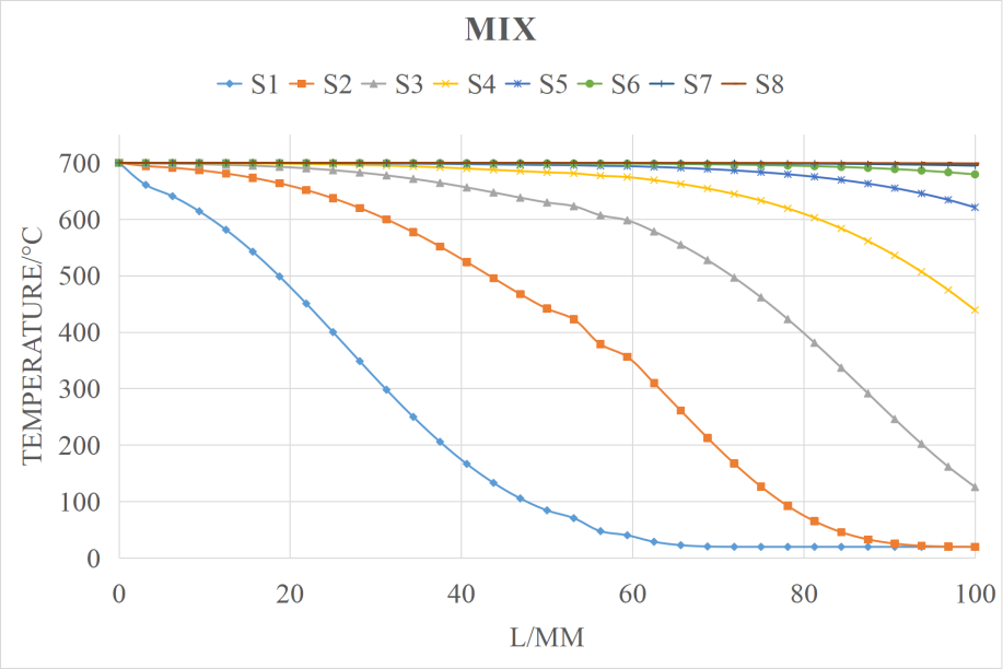
Figure 10. Optimized regenerator temperature distribution (Photo/Picture credit: Original).
By observing Figure 10., it can be concluded that the temperature of this modified regenerator with the hot site filled with copper foam increases rapidly as heat is absorbed when the gas passes through it. At the same time, the cooling side of the stainless-steel temperature gradually increases. Heat is transferred from the copper to the stainless steel, but the temperature does not rise as fast, suggesting the stainless steel's high specific heat capacity plays a role. Overall, the segmented regenerator absorbs heat quickly and stores more energy. This regenerator's choice increases heat absorption and reduces heat loss, thus increasing the overall efficiency of the Stirling engine.
5. Conclusion
This article first describes how the solar Stirling engine works and introduces the structure and principle of the engine regenerator. The paper compares the effect of filling various materials on the regenerator heat transfer performance through simulation experiments. The outcomes show that the copper foam regenerator has a shorter start-up time and a faster single heat transfer rate. In contrast, the stainless-steel mesh regenerator has a higher heat capacity. The design of a segmented regenerator, in which the two different materials are filled at different locations, has significantly improved the performance of the regenerator by making full use of the advantages of the materials themselves, and the feasibility of this regenerator has been verified through simulation experiments.
The simulations with the FLUENT software found that the copper foam has good thermal conductivity, meaning that heat is absorbed quickly. However, the specific heat capacity is small, and less heat is stored. On the other hand, the stainless-steel material was less thermally conductive, meaning that heat was absorbed more slowly, but had a higher specific heat capacity and stored more heat. In later simulations of the improved two-stage regenerator, it was found that filling the hot side with copper foam and the cold side with stainless steel mesh increased the heat absorption rate and stored more heat, reducing losses while increasing storage efficiency and effectively improving engine thermal efficiency.
To improve the quality of the Stirling engine, heat loss would be minimized by improving the utilization of external heat. This research aims to estimate the effect of different materials on the performance of the regenerator and explore how the regenerator can be improved by combining various materials. However, more detailed experiments on the proportion of combinations utilized still need to be included. More experiments and research are needed to explore the higher potential of the regenerator in the future. In conclusion, the regenerator represents a key element of the Stirling engine with great potential for future applications. Further research and development of the regenerator can significantly enhance Stirling engines' efficiency and reliability, significantly contributing to energy conversion and environmental protection.
References
[1]. Timoumi Y, Tlili I and Ben S 2008 Design and performance optimization of GPU-3 Stirling Engines Energy 33 1100.
[2]. Hafez A et al. 2016 Solar parabolic dish stirling engine system design, simulation and thermal analysis Energy Conversion and Management 126 60.
[3]. Scollo L et al. 2013 Twin Cylinder alpha stirling engine combined model and prototype redesign International Journal of Hydrogen Energy 38 1988.
[4]. Ipci D and Karabulut H 2018 Thermodynamic and dynamic analysis of an alpha type Stirling engine and numerical treatment Energy Conversion and Management 169 34.
[5]. Abuelyamen A and Ben-Mansour R 2018 Energy efficiency comparison of Stirling engine types (α, β, and γ) using detailed CFD modeling International Journal of Thermal Sciences 13 411.
[6]. Miura K, Izumida Y and Okuda K 2022 Achieving Carnot efficiency in a finite-power Brownian Carnot cycle with arbitrary temperature difference, Physical review.E 105 034102.
[7]. Sharma A, Shhukla S and Rai A 2011 Finite time thermodynamic analysis and optimization of solar-dish Stirling heat engine with regenerative losses Thermal Science 15 99.
[8]. Nielsen A 2019 Enhancing the Effectiveness of Stirling Engine Regenerators, University of Ontario Institute of Technology (Canada).
[9]. Bitsikas P, Rogdakis E and Dogkas G 2020 Numerical Study of Pressure Drop in Stirling Engine Regenerator Journal of Energy Engineering 146.
[10]. Matsuguchi A, Izumi T, Kitahama D, Takeuchi T and Kagawa N 2004 Design and Development of New Matrix for Stirling Engine Regenerator. Reston: American Institute of Aeronautics and Astronautics.
[11]. Kato Y and Baba K 2014 Empirical estimation of regenerator efficiency for a low temperature differential Stirling engine Renewable Energy 62 285.
[12]. Muthukumar P, Pannipara M, AL-Sehemi A and Savarimuthu P 2020 Highly enhanced bifunctional electrocatalytic activity of mixed copper–copper oxides on nickel foam via composition control New Journal of Chemistry 44 11993.
[13]. Kamath P, Balaji C and Venkateshan S 2013 Convection heat transfer from aluminium and copper foams in a vertical channel – an experimental study International Journal of Thermal Sciences 64 1.
[14]. Pang X, Guo Y, Chi J, Liang P, Shi Y and Zhao Y 2018 Comparison of Crevice Corrosion Susceptibility of 2205 Duplex Stainless Steel and 304 Stainless Steel in Hydrofluoric Acid Solution Corrosion Science and Protection Technology 30 362.
[15]. Kindra V, Komarov I, Osipov S, Zlyvko O and Maksimov I 2022 Feasibility Study of the CO2 Regenerator Parameters for Oxy-Fuel Combustion Power Cycle Inventions 7 66.
[16]. Chen W, Wong K and Chen H 2014 An experimental study on the performance of the moving regenerator for a [gamma]-type twin power piston Stirling engine Energy Conversion & Management 77 118.
[17]. Yu M, Xin F, Lai X, Xiao H, Liu Z and Liu W 2021 Study of oscillating flows through a novel constructal bifurcation Stirling regenerator Applied Thermal Engineering 184 1.
[18]. Cesar M, Andres R, Juan P, Baeyens J and Mazza G 2020 Comparing ANSYS Fluent® and OpenFOAM® simulations of Geldart A, B and D bubbling fluidized bed hydrodynamics International Journal of Numerical Methods for Heat & Fluid Flow 30 93.
[19]. Li P and Berkowitz B 2018 Controls on interactions between resident and infiltrating waters in porous media Advances in Water Resources 121 304.
[20]. Patel H and Meher R 2019 Effect of Heterogeneity on Imbibition Phenomena in Fluid Flow through Porous Media with Different Porous Materials Nonlinear Engineering 8 46.
[21]. Juncu G 2014 The influence of the porous media permeability on the unsteady conjugate forced convection heat transfer from a porous sphere embedded in a porous medium International Journal of Heat and Mass Transfer 77 1124.
Cite this article
Wu,K. (2023). Enhancing alpha solar stirling engine performance with regenerator. Theoretical and Natural Science,12,120-129.
Data availability
The datasets used and/or analyzed during the current study will be available from the authors upon reasonable request.
Disclaimer/Publisher's Note
The statements, opinions and data contained in all publications are solely those of the individual author(s) and contributor(s) and not of EWA Publishing and/or the editor(s). EWA Publishing and/or the editor(s) disclaim responsibility for any injury to people or property resulting from any ideas, methods, instructions or products referred to in the content.
About volume
Volume title: Proceedings of the 2023 International Conference on Mathematical Physics and Computational Simulation
© 2024 by the author(s). Licensee EWA Publishing, Oxford, UK. This article is an open access article distributed under the terms and
conditions of the Creative Commons Attribution (CC BY) license. Authors who
publish this series agree to the following terms:
1. Authors retain copyright and grant the series right of first publication with the work simultaneously licensed under a Creative Commons
Attribution License that allows others to share the work with an acknowledgment of the work's authorship and initial publication in this
series.
2. Authors are able to enter into separate, additional contractual arrangements for the non-exclusive distribution of the series's published
version of the work (e.g., post it to an institutional repository or publish it in a book), with an acknowledgment of its initial
publication in this series.
3. Authors are permitted and encouraged to post their work online (e.g., in institutional repositories or on their website) prior to and
during the submission process, as it can lead to productive exchanges, as well as earlier and greater citation of published work (See
Open access policy for details).
References
[1]. Timoumi Y, Tlili I and Ben S 2008 Design and performance optimization of GPU-3 Stirling Engines Energy 33 1100.
[2]. Hafez A et al. 2016 Solar parabolic dish stirling engine system design, simulation and thermal analysis Energy Conversion and Management 126 60.
[3]. Scollo L et al. 2013 Twin Cylinder alpha stirling engine combined model and prototype redesign International Journal of Hydrogen Energy 38 1988.
[4]. Ipci D and Karabulut H 2018 Thermodynamic and dynamic analysis of an alpha type Stirling engine and numerical treatment Energy Conversion and Management 169 34.
[5]. Abuelyamen A and Ben-Mansour R 2018 Energy efficiency comparison of Stirling engine types (α, β, and γ) using detailed CFD modeling International Journal of Thermal Sciences 13 411.
[6]. Miura K, Izumida Y and Okuda K 2022 Achieving Carnot efficiency in a finite-power Brownian Carnot cycle with arbitrary temperature difference, Physical review.E 105 034102.
[7]. Sharma A, Shhukla S and Rai A 2011 Finite time thermodynamic analysis and optimization of solar-dish Stirling heat engine with regenerative losses Thermal Science 15 99.
[8]. Nielsen A 2019 Enhancing the Effectiveness of Stirling Engine Regenerators, University of Ontario Institute of Technology (Canada).
[9]. Bitsikas P, Rogdakis E and Dogkas G 2020 Numerical Study of Pressure Drop in Stirling Engine Regenerator Journal of Energy Engineering 146.
[10]. Matsuguchi A, Izumi T, Kitahama D, Takeuchi T and Kagawa N 2004 Design and Development of New Matrix for Stirling Engine Regenerator. Reston: American Institute of Aeronautics and Astronautics.
[11]. Kato Y and Baba K 2014 Empirical estimation of regenerator efficiency for a low temperature differential Stirling engine Renewable Energy 62 285.
[12]. Muthukumar P, Pannipara M, AL-Sehemi A and Savarimuthu P 2020 Highly enhanced bifunctional electrocatalytic activity of mixed copper–copper oxides on nickel foam via composition control New Journal of Chemistry 44 11993.
[13]. Kamath P, Balaji C and Venkateshan S 2013 Convection heat transfer from aluminium and copper foams in a vertical channel – an experimental study International Journal of Thermal Sciences 64 1.
[14]. Pang X, Guo Y, Chi J, Liang P, Shi Y and Zhao Y 2018 Comparison of Crevice Corrosion Susceptibility of 2205 Duplex Stainless Steel and 304 Stainless Steel in Hydrofluoric Acid Solution Corrosion Science and Protection Technology 30 362.
[15]. Kindra V, Komarov I, Osipov S, Zlyvko O and Maksimov I 2022 Feasibility Study of the CO2 Regenerator Parameters for Oxy-Fuel Combustion Power Cycle Inventions 7 66.
[16]. Chen W, Wong K and Chen H 2014 An experimental study on the performance of the moving regenerator for a [gamma]-type twin power piston Stirling engine Energy Conversion & Management 77 118.
[17]. Yu M, Xin F, Lai X, Xiao H, Liu Z and Liu W 2021 Study of oscillating flows through a novel constructal bifurcation Stirling regenerator Applied Thermal Engineering 184 1.
[18]. Cesar M, Andres R, Juan P, Baeyens J and Mazza G 2020 Comparing ANSYS Fluent® and OpenFOAM® simulations of Geldart A, B and D bubbling fluidized bed hydrodynamics International Journal of Numerical Methods for Heat & Fluid Flow 30 93.
[19]. Li P and Berkowitz B 2018 Controls on interactions between resident and infiltrating waters in porous media Advances in Water Resources 121 304.
[20]. Patel H and Meher R 2019 Effect of Heterogeneity on Imbibition Phenomena in Fluid Flow through Porous Media with Different Porous Materials Nonlinear Engineering 8 46.
[21]. Juncu G 2014 The influence of the porous media permeability on the unsteady conjugate forced convection heat transfer from a porous sphere embedded in a porous medium International Journal of Heat and Mass Transfer 77 1124.