


1. Introduction
The ITER project is the currently world’s largest experimental nuclear fusion engineering facility, aiming to demonstrate the scientific and technological feasibility of commercial fusion power generation. Over 170 independent plant instrumentation and control (I&C) systems are embedded, functioning as the interface layer between the central control system and numerous plant equipment. These systems are responsible for control and monitoring of the plant facilities under the coordination of the central control systems, thereby ensuring effective operation and administration of the integrated devices. To guarantee standardization and integration consistency for the I&C systems developed by various agencies, ITER has established the Plant Control System Design Handbook (PCDH) with technical specifications and design standards [1-6].
The ITER GIS is part of the ITER fueling system, responsible for providing working fuel gases (H2, D2, T2, He) and impurity gases (Ne, Ar, N2) into the tokamak torus vacuum vessel [7]. To prevent damage to the device investment, the GIS requires a dedicated interlock system to rapidly respond to abnormal operation conditions. This paper describes the GIS plant interlock system (PIS) design.
In section 2, the interlock function to be implemented and the corresponding integrity requirements have been introduced. In section 3, the scope of the GIS PIS with the ITER control system architecture is described. Details on the redundant fail-safe hardware architecture and modular software designs are presented in sections 4 and 5 respectively.
2. Interlock function and requirements
T The ITER GIS PIS is tasked with executing the central interlock function A-FUEL-0002 which forcibly places the GIS system into a safe state upon detecting abnormal trigger conditions. Such triggers include the activation of the ITER disruption mitigation system or when the tokamak operation conditions are not met [8]. The function description and the ITER interlock integrated level is described in the Table 1. To avoid conflict with another ITER safety system intended for personnel and environmental protection, ITER has expressly defined the 3IL (ITER Interlock Integrity Level). The 3IL level has a direct mapping to SIL 2 under the IEC 61508 standard, which governs functional safety for programmable electronic systems.
Table 1. GIS PIS Interlock Function
Function Code | Function name | 3IL |
A-FUEL-0002 | Stop / Inhibit Gas Injection System | 2 |
The functional requirement for A-FUEL-0002 is that all isolation valves on the gas injection lines equipped in both the fueling gas valve boxes (GVB) and pellet gas valve boxes (see Figure 1) shall be closed when the GIS system enters the safe state. This effectively cuts off any working gas supply to the vacuum vessel, shielding the GIS from the tokamak plasma operation status and prevent further hazards from the working gases. The injection line isolation valves selected are pneumatic isolation valves controlled by solenoid valves that govern the supply of compressed driving gas. According to the defined safe state for the GIS, the injection line isolation valves should remain closed when the GIS is in the safe state to following to the fail-safe principle. Therefore, normally closed valves have been chosen as injection line isolation valves.
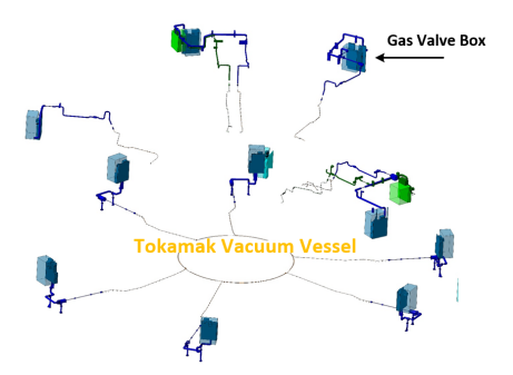
Figure 1. Distribution of Gas Injection System Gas Valve Boxes
3. System Overview
The ITER instrumentation and control (I&C) architecture implements a dual-layer structure consisting of central and numerous plant-based I&C systems. Three physically separated subsystems constitute this framework and are prioritized by functionality, the COntrol, Data Access and Communication (CODAC) system handles overall device operation coordination, the Interlock control system executes investment protection duties, while the Safety system specializes in personnel and environmental security. As a plant interlock system, the GIS Plant interlock system is highlighted in the yellow portion in the ITER overall architecture in Figure 2. It communicates with Central interlock system via central interlock Network (CIN) and transmit information with CODAC through plant operational Network (PON) [9,10].
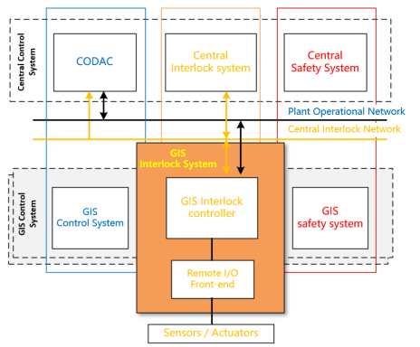
Figure 2. Distribution of Gas Injection System Gas Valve Boxes
Under the ITER interlock system architecture, the A-FUEL-0002 function is classified as a central interlock function (see Table 1), designating the GIS interlock system as an actuation unit. Upon receiving trigger signal from the Central Interlock System, corresponding investment protection function will be executed by the GIS interlock system, and can override conventional GIS I&C control logic to place the GIS system into a safe state, the GIS PIS function scope is outlined in Figure 3.
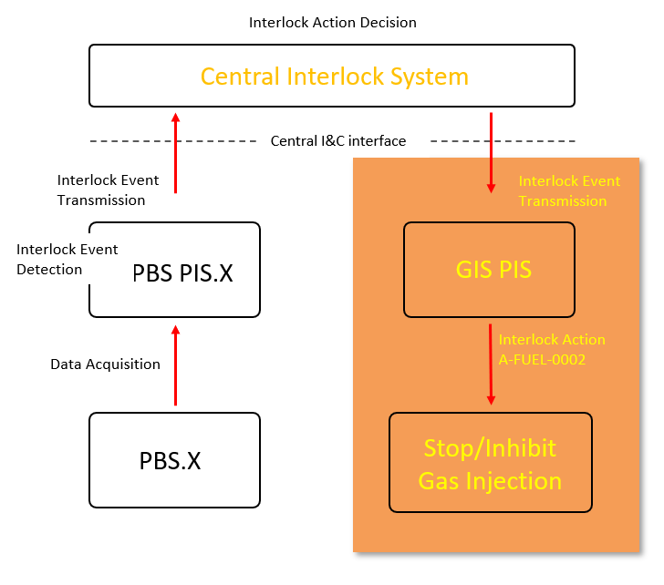
Figure 3. The Scope of ITER GIS PIS
4. Physical Architecture
To satisfy the ITER 3IL-2 interlock integrity level specifications for the GIS PIS interlock system. GIS PIS hardware architecture adopts a 1oo2 redundant architecture with a hardware fault tolerance (HFT) factor of 1. Moreover, considering the slow GIS gas dynamic response, safety-oriented Siemens S7-400F programmable logic controller (PLC) with integrated fail-safe functions has been selected for the interlock system implementation. The fail-safe PLCs interface with remote I/O stations via Profinet protocol.
Dual-redundant connections are configured to interface with the Central Interlock Network (CIN) for transmitting critical interlock function A-FUEL-0002 command data. Non-critical data including the device diagnostics, reset controls, and other operational parameters etc. are communicated over the Plant Operation Network (PON). The detailed hardware architecture is represented in Figure 4.
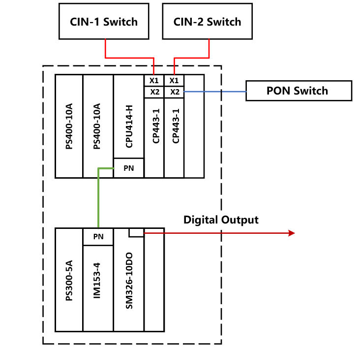
Figure 4. The Hardware architecture of GIS PIS
Due to space constraints within the gas valve boxes, with additional valves configuration is impossible. Thus, a strategy of sharing existing valves between conventional control and interlock functions has been adopted as depicted in Figure 5. Certified safety relays per IEC 61508 SIL 3 specifications are integrated into conventional cubicles, enabling prioritizing supervision for interlock function over conventional control. Thereby, interlock commands override conventional control logic targeting the isolation valves when interlock trigger is detected. Moreover, fail-closed characteristics are specified for the chosen valve models to uphold the fail-safe principle applied to the interlock function. Also, with direct fiber optic connections to each control cubicle other than the distributed GVBs can minimize complex, system-spanning signal cabling while enhancing electrical noise immunity. The functional implementation scheme is illustrated in the Figure 5.
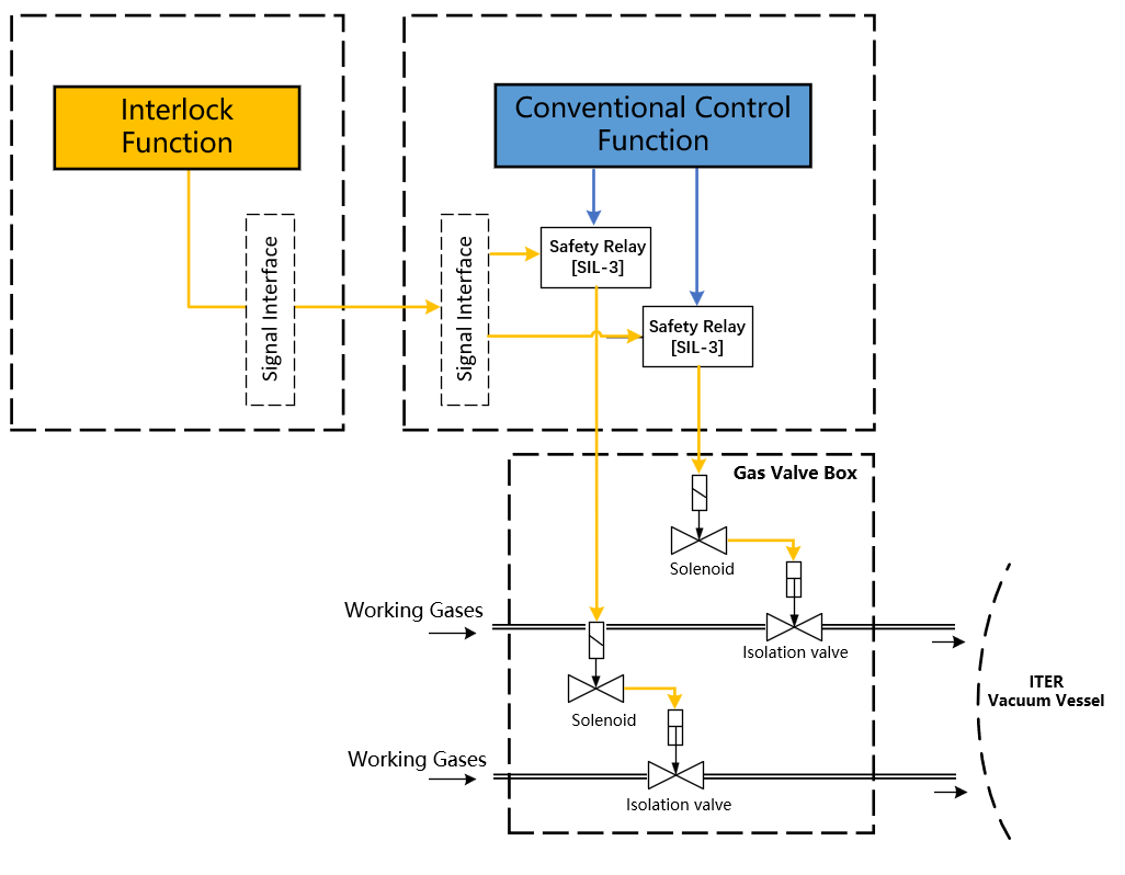
Figure 5. The Scheme of Interlock Function Implementation
5. Software Architecture
A modular software architecture is implemented for the GIS interlock system program. As depicted in Figure 6, different functions are separated into distinct and independent modules to facilitate code organization, maintenance, debugging and runtime operation. The software is separated into the safety-oriented PLC program and the non-critical standard program. Modules directly involved in executing GIS interlock function A-FUEL-0002 are implemented on the PLC safety program, while standard logic is coded into the standard program. Data exchange or conversion between the safety and standard programs are handled using F-Blocks.
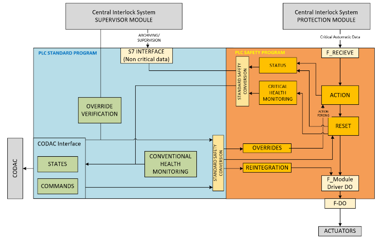
Figure 6. The Software Architecture of GIS PIS
6. Conclusion
In summary, this paper has presented a preliminary design for the ITER Gas Injection System (GIS) interlock system, which executes the A-FUEL-0002 function to protect device investments by rapidly placing the GIS subsystem into a safe state during abnormal conditions.
Following ITER guidelines, a redundant architecture using Siemens S7-400F fail-safe programmable logic controllers has been adopted to meet the 3IL-2 (SIL-2) ITER interlock integrity requirements. Dual-redundant links enable critical data exchanges with the Central Interlock Network, while non-priority operational parameters communicate over the Plant Operational network.
Additionally, a modular software architecture partitions the interlock logic into dedicated safety and standard programs. Such segmentation combined with extensive use of IEC 61131 frameworks streamlines development and maintains long-term maintainability.
The presented fault-tolerant designs grant stability, availability, and control integrity to the ITER investment protection, and can also serves as the reference for other large-scale plant or scientific facilities.
References
[1]. Journeaux J Y, Joonekindt D, Klotz W D, et al. Instrumentation and control standardization in the ITER project [J]. Fusion Engineering and Design, 2011, 86(6-8), pp.1157-1162.
[2]. Wallander, A., Abadie, L., Dave, H., et al. ITER instrumentation and control—Status and plans. [J]. Fusion Engineering and Design, 2010, 85(3-4), pp.529-534.
[3]. Wallander, A., Abadie, L., Dave, H., et al. ITER instrumentation and control—Status and plans. [J]. Fusion Engineering and Design, 2010, 85(3-4), pp.529-534.
[4]. Davis, W., Wallander, A. and I. Yonekawa. Current Status of ITER I&C system as integration begins [J]. Fusion Engineering and Design, 2016, 112, pp.788–795.
[5]. Davis, W., Wallander, A. and I. Yonekawa. Current Status of ITER I&C system as integration begins [J]. Fusion Engineering and Design, 2016, 112, pp.788–795.
[6]. Lister J B, Farthing J W, Greenwald M, et al. The status of ITER CODAC Conceptual design [J]. Fusion Engineering and design, 2008,83(2-3), pp.164-169.
[7]. Z. W. Xia, W. Li,a X. G. Liu, et al. Structural Design for ITER Gas Injection System Gas Fueling Gas Valve Box [J]. Fusion Science and technology, 2020, 76, pp.848-856.
[8]. Kukushkin, A.S., Polevoi, A.R., Pacher, H.D., Pacher, G.W. and Pitts, R.A. (2011). Physics requirements on fuel throughput in ITER. Journal of Nuclear Materials, 415(1), pp.S497–S500.
[9]. L. Scibile, Journeaux, J.Y., Klotz, W.-D., et al. A. (2009). An overview of the ITER interlock and Interlock and safety systems. Proceedings of ICALEPCS 2009, Kobe, Japan.
[10]. Liu, G., Makijarvi, P. and Pons, N. The ITER CODAC network design [J]. Fusion Engineering and Design, 2018, 130, pp.6–10.
Cite this article
Gu,Z.;Zhao,Y.;Gong,W.;Zhiwei,X.;Wei,L.;Bo,L. (2024). Design of SIL-2 interlock function for tokamak fusion reactor. Applied and Computational Engineering,65,204-209.
Data availability
The datasets used and/or analyzed during the current study will be available from the authors upon reasonable request.
Disclaimer/Publisher's Note
The statements, opinions and data contained in all publications are solely those of the individual author(s) and contributor(s) and not of EWA Publishing and/or the editor(s). EWA Publishing and/or the editor(s) disclaim responsibility for any injury to people or property resulting from any ideas, methods, instructions or products referred to in the content.
About volume
Volume title: Proceedings of Urban Intelligence: Machine Learning in Smart City Solutions - CONFSEML 2024
© 2024 by the author(s). Licensee EWA Publishing, Oxford, UK. This article is an open access article distributed under the terms and
conditions of the Creative Commons Attribution (CC BY) license. Authors who
publish this series agree to the following terms:
1. Authors retain copyright and grant the series right of first publication with the work simultaneously licensed under a Creative Commons
Attribution License that allows others to share the work with an acknowledgment of the work's authorship and initial publication in this
series.
2. Authors are able to enter into separate, additional contractual arrangements for the non-exclusive distribution of the series's published
version of the work (e.g., post it to an institutional repository or publish it in a book), with an acknowledgment of its initial
publication in this series.
3. Authors are permitted and encouraged to post their work online (e.g., in institutional repositories or on their website) prior to and
during the submission process, as it can lead to productive exchanges, as well as earlier and greater citation of published work (See
Open access policy for details).
References
[1]. Journeaux J Y, Joonekindt D, Klotz W D, et al. Instrumentation and control standardization in the ITER project [J]. Fusion Engineering and Design, 2011, 86(6-8), pp.1157-1162.
[2]. Wallander, A., Abadie, L., Dave, H., et al. ITER instrumentation and control—Status and plans. [J]. Fusion Engineering and Design, 2010, 85(3-4), pp.529-534.
[3]. Wallander, A., Abadie, L., Dave, H., et al. ITER instrumentation and control—Status and plans. [J]. Fusion Engineering and Design, 2010, 85(3-4), pp.529-534.
[4]. Davis, W., Wallander, A. and I. Yonekawa. Current Status of ITER I&C system as integration begins [J]. Fusion Engineering and Design, 2016, 112, pp.788–795.
[5]. Davis, W., Wallander, A. and I. Yonekawa. Current Status of ITER I&C system as integration begins [J]. Fusion Engineering and Design, 2016, 112, pp.788–795.
[6]. Lister J B, Farthing J W, Greenwald M, et al. The status of ITER CODAC Conceptual design [J]. Fusion Engineering and design, 2008,83(2-3), pp.164-169.
[7]. Z. W. Xia, W. Li,a X. G. Liu, et al. Structural Design for ITER Gas Injection System Gas Fueling Gas Valve Box [J]. Fusion Science and technology, 2020, 76, pp.848-856.
[8]. Kukushkin, A.S., Polevoi, A.R., Pacher, H.D., Pacher, G.W. and Pitts, R.A. (2011). Physics requirements on fuel throughput in ITER. Journal of Nuclear Materials, 415(1), pp.S497–S500.
[9]. L. Scibile, Journeaux, J.Y., Klotz, W.-D., et al. A. (2009). An overview of the ITER interlock and Interlock and safety systems. Proceedings of ICALEPCS 2009, Kobe, Japan.
[10]. Liu, G., Makijarvi, P. and Pons, N. The ITER CODAC network design [J]. Fusion Engineering and Design, 2018, 130, pp.6–10.