


1. Introduction
Given the swift expansion of the world’s population and economy, the decline in environmental quality caused by global warming, frequent climate disasters, ecosystem damage, sea level rise and other problems makes the world energy structure is changing, which means many countries start to develop their new energy industry and technology in order to meet their growing demand for energy. Therefore, promoting the energy transformation and innovation has become a new focus, and photovoltaic (PV) power generation as a green energy source is the focus of attention [1-6].
Compare to other new energy, photovoltaic power generation can make individuals or enterprises energy independent to a certain extent, and the installation location does not have too many requirements, which is suitable for applications in different scenarios.
Based on whether transformers are present or not, photovoltaic grid-connected inverter systems can be classified as isolated or non-isolated. The isolation is divided into power frequency and high frequency, and Figure 1 depicts the power frequency isolation photovoltaic grid-connected system.
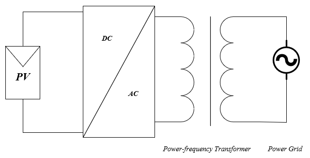
Figure 1. Transformer-based grid-connected PV inverter [1].
Power frequency isolated photovoltaic grid-connected systems have the advantages of high safety and prevent saturation of the distribution transformers, while the high frequency isolated photovoltaic grid-connected systems reduce the volume and weight on the basis of the previous systems and have higher working efficiency. However, there is a power loss in the way that transformers convert electrical energy into magnetic energy and then turn back to the electrical energy. The loss of transformers in the kilowatt class can reach 5%. Therefore, in order to avoid forced galvanic isolation, a non-isolated photovoltaic grid-connected system without transformers is presented, which reduces the quality and cost of the system and makes the structure simpler, as shown in Figure 2.
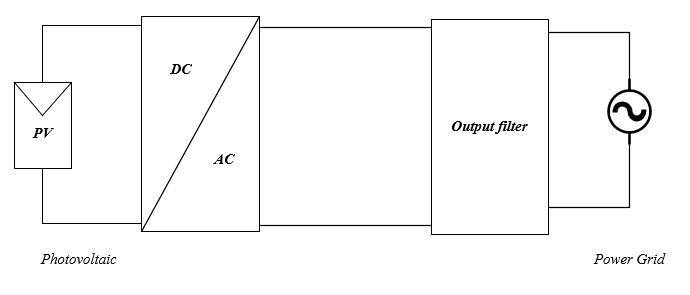
Figure 2. Transformerless grid-connected PV inverter [1].
The broad application prospects of photovoltaic systems make the guarantee of their safety become important, and the most important of them is the influence of leakage current on system stability.
In recent years, people have a deeper understanding of the threat of leakage current, and with the development of leakage current suppression methods and technologies, standards and regulations around the world require electrical systems and appliances to establish strict leakage current suppression standards. In order to reduce harmonic disturbance and electromagnetic interference, and improve energy conversion efficiency, more and more three-phase inverters use multilevel topology inverters that can output higher quality alternating current, which could be widely used in the field of renewable energy, electric vehicle charging piles and high-performance industrial drives and have the potentially developed space in the real future.
However, if there is no control technology for resonant peaks, the resonant capacitor and resonant inductor will form a resonant loop near the resonant frequency, and produce high-frequency current ripple with high-order characteristics, so that there is undamped resonance in the grid-connected current, resulting in system instability and increasing the harmonic distortion rate of the grid-side current, which could make the system produces a large leakage current. The classification of current suppression methods is shown in Figure 3.
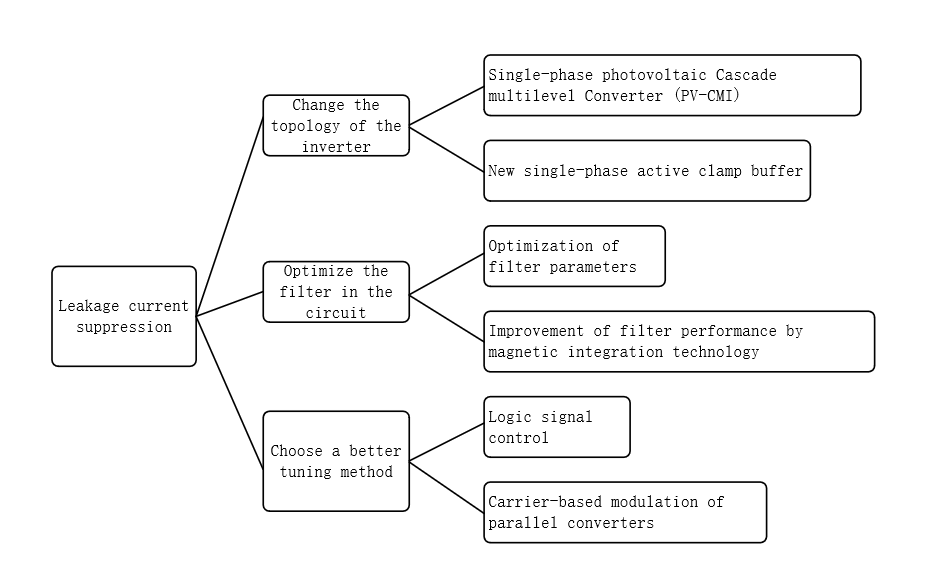
Figure 3. Classification of leakage current suppression methods [2].
At present, the topology of three-phase inverter and the optimization of filters to improve the reliability of the power supply of DC distribution systems have also been researched. Therefore, this paper reviews the topology of inverter network, the optimization of filter efficiency and the improvement of modulation mode, and looks forward to the future development trend of photovoltaic inverters, which provides a reference for following research.
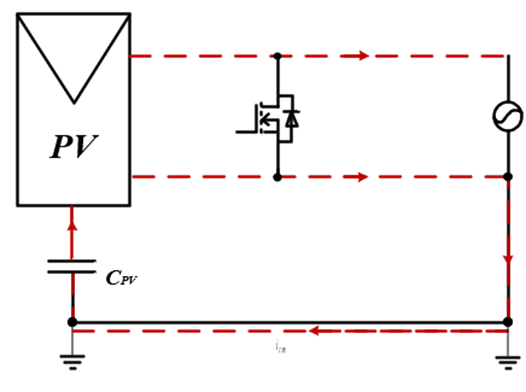
Figure 4. Equivalent model of leakage current generation [2].
2. The mechanism of leakage current formation
A direct electrical connection is established between the power grid and the photovoltaic panel. The parasitic capacitance of the photovoltaic array to the ground creates a capacitive coupling between the array and the ground, and a common-mode resonance loop is formed between the parasitic capacitance, the inverter, and the grid line impedance. As illustrated in Figure 4, the common-mode resonant loop produces a corresponding common-mode current when the common-mode voltage is excited, and a leakage current is produced when the DC side of the inverter shifts the voltage to ground.
3. Topology
Since power electronics technology has advanced, multilevel converters have attracted attention concerning single-phase solar inverters because of their high level number and low harmonic content, but their control strategies are complex and their structure is redundant. Therefore, the optimization of other structures is a hotspot. This section describes the different single-phase PV inverter topologies.
3.1. Single-phase photovoltaic cascade multilevel converter
The traditional single-phase photovoltaic cascade multilevel converter (PV-CMI) consisting of n HB modules. Using a multilevel converter as a reference, the larger the n, the higher the number of levels, the less harmonic content, and the fewer power switching devices required. Through the analyzed of leakage current of single-phase PV-CMI, [1] concluded that in single-phase photovoltaic cascade converters, there is not only common-mode leakage current, but also differential-mode leakage current, while the traditional improvements for non-isolated single-phase full-bridge inverter systems such as H5, Heric and other changes cannot bring effectively optimized.
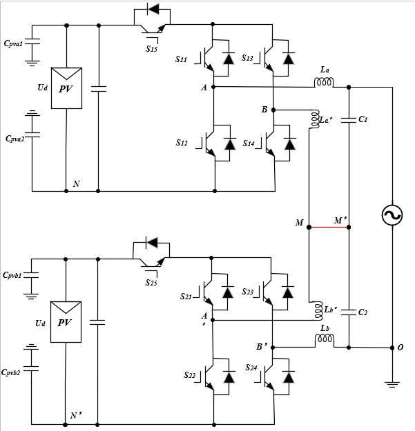
Figure 5. Topology of new PV-CMI [1].
The H5 module is primarily used to ensure the stability of the common-mode voltage. [2–3] offers a method for optimizing the circuit topology by combining the H5 circuit with capacitors and inductors, as shown in Figure 5. This lessens the impact of the differential-mode voltage and efficiently controls the common-mode leakage current. While the capacitors are used to divide the voltage and lower the total current in the area, the inductors are employed to prevent the differential-mode voltage from having an impact on the leakage current. The circuit will become excessively complex as IGBTs and capacitor inductance increase, and leakage current will become parasitic in the inductor, which is the same issue as multilevel converters.
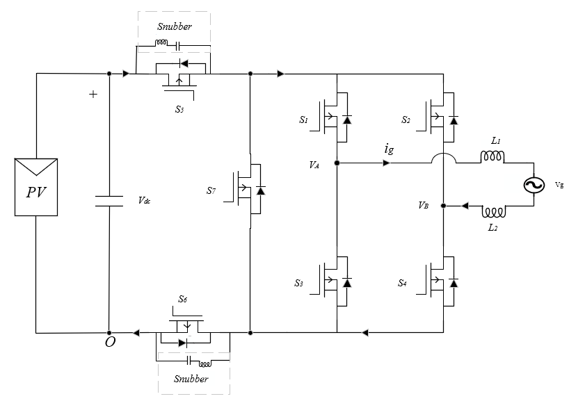
Figure 6. Novel single-phase Active Clamp buffer topology
3.2. New single-phase active clamping buffer
One of the main reasons for the leakage current in a single photovoltaic inverter circuit is that there is a dead-time effect in the circuit operation during modulation, [4] and a logic topology is proposed to indirectly reduce the leakage current by reducing the dead time as shown in Figure 6.
The new topology adds three complementary switches on the basis of the tradition, and at the same time uses the wide bandgap device GaN HEMT instead of IGBT, the relatively small dielectric constant of GaN can reduce the parameters of parasitic capacitance in the photovoltaic power, and its higher electron mobility, saturation drift velocity and no reverse recovery phenomenon [5] can bring higher efficiency and shorter dead time which compared with IGBT. What’s more, its on-voltage not only has to overcome the on-voltage, but also has its own off-voltage, that’s why the spike amplitude is smaller. Therefore, the voltage fluctuation can be reduced and the oscillation of the leakage current can be alleviated, this circuit uses LC succession to decouple the circuit to prevent a large impact on the power grid when the output voltage is 0, and at the same time has the advantage of system simplicity.
Although GaN HEMT could bring a shorter dead time than IGBT, it has a high anti-conduction loss, and according to the complex voltage error expression described in [6], the traditional compensation dead time method is difficult to ensure the effect. At the same time, the price of GaN HEMT is high, and maximum power point tracking control of single-power system will be more difficult.
4. Optimization of filter
During the conversion of solar energy collected by single-phase photovoltaic inverters into AC power, a significant amount of harmonics are generated. This is primarily due to the nature of these inverters as power electronic switching devices. To ensure the converted AC power complies with electrical energy quality standards, filters are commonly used in engineering applications to eliminate these harmonics.
In photovoltaic systems, LCL filters are among the most widely utilized filtering solutions. With their ability to provide exceptional harmonic attenuation even when the total inductance is minimal, these filters greatly enhance both the power density and the dynamic performance of the system. The following is a summary of recent advancements in LCL filter technology.
4.1. Optimization of filter parameters
The following five guidelines are frequently used as a basis for filter design:
1) Reduce as much of the energy that has been stored in the filter as you can.
2) Minimize the stored energy in the filter as much as possible.
3) Reduce the amount of reactive power that the filter capacitors produce.
4) Lower the IGBT switches’ conduction and switching losses.
5) Enhance the damping capabilities.
A technique for enhancing an LCL filter’s performance through parameter adjustments is given in [7]. Assuming that the inductors and capacitors have zero resistance, equation (1) is an LCL filter’s transfer function:
\( \frac{Ig(s)}{vⅈ(s)}=\frac{1}{{L_{g}}{L_{1}}\cdot {C_{f}}{S^{3}}+({L_{i}}+{L_{g}})s} \) (1)
Equation (2) represents the resonant frequency of an LCL filter:
\( ω_{rⅇs}^{2}=\frac{({L_{i}}+{L_{g}})}{{L_{i}}Lg{C_{f}}} \) (2)
The equation can be expanded as equation (3):
\( {L_{T}}{C_{f}}=\frac{{k^{2}}}{4{π^{2}}f_{sw}^{2}}\frac{{(1+u)^{2}}}{u} \) (3)
It is evident that larger filter components are produced by a higher value of k (lower frequency). The equation can be differentiated with respect to u to determine that u = 1 is the lowest value of LTF that can be obtained. It is possible to achieve the least stored energy of the LCL filter as well as enhanced robust filtering of gate inductance variation when the gate-side and inverter-side inductances are equal. The weighting of cost and energy usage while choosing inductance and capacitance is shown in the equation (4).
\( E=0.5{L_{T}}{W_{L}}{ⅈ^{2}}+0.5{C_{f}}V_{g}^{2}{W_{C}} \) (4)
After incorporating the weighting factor α, the new formula can be obtained as equation (5):
\( OF=\frac{E}{{E_{max}}}α+\frac{THD}{THDmax}(1-α) \) (5)
Under the guidance of this formula, the optimal filter parameters can be within the scope of IEEE standards.
4.2. Magnetic integration technology for improving filtering performance
The LCL filter has better harmonic attenuation even in situations with lower total inductance. But this calls for one or two more magnetic cores. Wiring the converter side and grid side inductor windings onto a single magnetic core using magnetic integration technology is one potential remedy. But as [8] notes, integrated LCL filters perform poorly in terms of high-frequency harmonic attenuation due to inherent magnetic coupling.
The maximum size of the Type I iron core is limited by conventional techniques to counterbalance the magnetic coupling, which limits the direct coupling method’s potential. Moreover, the high magnetic permeability of Type I iron cores, which are widely used in the common magnetic flux channel, comes at a significant cost.
The problem noted before is tackled in this study by adding a second winding on the common magnetic flux line along with the filtering capacitor branch in series. The grid side and converter side inductor windings’ magnetic coupling is effectively reduced by employing this technique. Thus, the capability of high-frequency harmonic attenuation is recovered. The magnetic core’s weight and dimensions are significantly decreased by the refining process, which makes use of direct connection. Additionally, it provides increased design flexibility by removing the requirement to include air gaps to the shared magnetic flux channel.
5. Optimizing Modulation Strategy
When a single-phase photovoltaic inverter operates, it connects the photovoltaic panels with the grid to store solar energy. During the process of converting the DC from the photovoltaic cells into AC power received by the grid, both high and low-order harmonics can be generated. For circuits with single-phase topology, PWM modulation is widely applied. SPWM and SVPWNM are the most basic modulation methods used in inverters. The SPWM control scheme compares the modulation wave with a triangular carrier wave and obtains switch signals through logical judgments. However, inverter circuit typically has constant and unchanging inductor current, so using this method requires large energy storage inductors to maintain constant current, which increases system cost, size, and reduces efficiency. Moreover, when the output power of the photovoltaic inverter is high, the lower the frequency at which the inverter switches off, the higher the content of high-order harmonics it produces. To address the aforementioned issues, this paper proposes two new modulation strategies: closed-loop control strategy and carrier-based modulation for parallel converters.
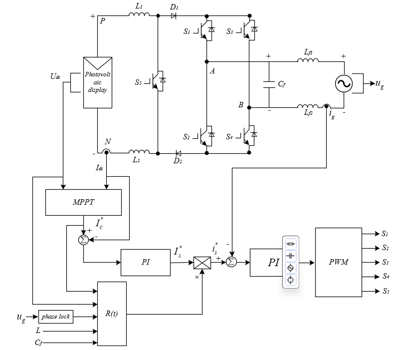
Figure 7. Single-phase current type PV inverter using PI control schematic.
5.1. Closed-loop control strategy
The literature [9] describes a dual-loop control method for the current outer loop of a DC-side inductance. The DC-side outer loop can control the DC-side inductance current to make it more stable, reduce large fluctuations caused by external disturbances. The control principle is shown in Figure 7. Single-phase current inverters adopt grid current inner loop control, with equation (6) representing the modulation function of this closed-loop control strategy.
\( r(t)=\frac{\frac{2({U_{dc}}-r{I_{c}})}{{V_{m}}}sin(ωt)}{1+\frac{{U_{dc}}-{r_{L}}{I_{c}}}{2ωL{I_{c}}}sin(2ωt)+\frac{{C_{f}}V_{m}^{2}}{4LI_{c}^{2}}cos(2ωt)} \) (6)
If we assume the load resistance is R, the expression for the DC inductance current is as equation (7).
\( {i_{L}}={I_{c}}+\frac{{U_{dc}}-{r_{L}}{I_{c}}}{2ωL}sin(2ωt)+\frac{R{C_{f}}({U_{dc}}-{r_{L}}{I_{c}})}{2L}cos(2ωt) \) (7)
The output of the DC-side outer loop regulator is multiplied by the modulation function obtained from formula (2) to obtain the grid current reference signal is*. After subtracting the grid current ig ,it is transmitted to the DSP event manager through the PI controller to obtain the required PWM drive pulses.
5.2. Carrier-based modulation of parallel converter
A proposed solution to achieve high current quality requirements and minimize leakage current in high-power solar applications is an improved carrier-based modulation (ICBM) for parallel converters [10]. This addresses the issue of using unsuitable phase shift angles to optimize total current ripple, resulting in improved total output current quality.
Primarily, the carrier-based modulation of parallel converters minimizes voltage variations in switches by adjusting each phase carrier’s initial phase shift angles in the converter. This reduction in leakage current magnitude ensures the total output voltage remains unaffected.
6. Advantages, Disadvantages, and Comparison of Three Methods
6.1. In Terms of Topology
The enhancement of the single-phase Photovoltaic Cascaded Multilevel Inverter (PV-CMI) considers the influence of both common-mode and differential-mode voltages on leakage current, while ensuring voltage stability. However, this enhancement leads to an increase in structural complexity. For the advancement of the new single-phase active clamp buffer, the implementation of GaN HEMT, replacing IGBT, effectively reduces the dead time along with the peak of leakage current. However, this comes with a high cost, and the complexity of GaN HEMT’s voltage error expression makes it a challenge to secure effectiveness using traditional methods of compensating for dead time.
6.2. In Terms of Filters
The refinement of filter parameters theoretically lowers the energy stored within the filter, subsequently reducing component size and enabling low power consumption. Additional considerations regarding the material cost and energy use are provided for making cost-effective decisions. However, in practical engineering applications, the challenge lies in maintaining a lower price while increasing the filter’s performance. The integration of magnetic technology significantly lessens the weight and volume of filter inductors, further driving down production costs.
6.3. In Terms of Modulation
Closed-loop control strategies serve to maintain consistent energy storage inductor current whilst modulating the desired output current. This approach, in turn, reduces harmonic distortion, boosts the usage of current, and minimizes external disruptions. The introduction of a new, carrier-based modulation method effectively removes the influence of ripple current on the DC side on the output waveform of current-inverter types. This not only restrains low-order harmonics and eradicates the impact of the DC-side’s current ripple on output waveform quality, but it also lessens the inductance on the DC side, thus diminishing system costs and reducing system volume.
6.4. Comparisons
The enhancements in the new single-phase active clamp buffer, filter parameters, and logic signal control have all been proposed from a theoretical standpoint. Nevertheless, cost concerns and practical constraints impede their real-world implementation. In specific engineering designs, these improvement methods necessitate evaluation and selection based on multiple factors. Magnetic integration technology and the new carrier-based modulation method both streamline the system’s volume and decrease system costs, making them broadly applicable. Conversely, the advancement of the single-phase PV-CMI adds complexity to the system structure, which calls for thorough deliberation in practical engineering applications. The comparison between different method is summarized in Table 1.
Table 1. Summary of improvement methods
Improvement target | Pros and cons |
Single-phase photovoltaic cascaded multilevel inverter (PV-CMI) | Complex structure |
New type single-phase active clamping buffer. | Higher costs, more complex structure |
Filter parameters. | Higher costs |
Magnetic integration technology | Reducing weight, volume and costs |
New Single-Phase Active Clamp Buffer. | requiring higher accuracy |
New carrier-based modulation method | Enhancing the quality of the output, reducing costs and minimizing system size. |
Looking forward, leakage current issues will continue to be a subject of high priority. As the demand for electrical safety keeps increasing, the proliferation and application of leakage current suppression techniques will expand substantially to ensure the safety of people and their assets. However, addressing the leakage current problem requires a multi-pronged approach. Beyond the development and implementation of leakage current suppression techniques, it is also essential to amplify efforts in electrical safety education and management, raise the public awareness and competence in electrical safety, and reinforce the regulation and inspection of electrical products to more effectively tackle the problem of leakage current.
7. Conclusion
This paper presents a comprehensive study on three methods for mitigating leakage current in single-phase photovoltaic inverters. It conducts an in-depth analysis of the most effective suppression strategies that have emerged in recent years, and provides an extensive summary of the current research in this field, which could serve as a valuable reference for future researchers. With respect to the conventional circuit topology, enhancements can be made by integrating the H5 circuit with capacitors and inductors. Such modifications have proven to effectively mitigate the impact of differential mode voltages that exist apart from common mode voltage and, by reducing the dead time, the leakage current can also be indirectly suppressed. The efficiency of filters can be boosted not only through parameter adjustments but also by embracing magnetic integration technology, which reinforces the performance in attenuating high-frequency harmonics. By employing modulation strategies founded on both energy storage inductor current control and carrier-based modulation (ICBM), the adverse effects of leakage current can be minimized. These strategies aim at boosting current utilization and enhancing current quality.
Authors Contribution
All the authors contributed equally and their names were listed in alphabetical order.
References
[1]. Zhang Xing, Wu Mengze, Wang Mingda et al. Review on leakage current suppression and power balance control of single-phase photovoltaic cascaded multilevel inverters [J]. Automation of Electric Power Systems, 2019,47(09):202-215.
[2]. X. Guo and X. Jia, “Hardware-Based Cascaded Topology and Modulation Strategy With Leakage Current Reduction for Transformerless PV Systems,” IEEE Transactions on Industrial Electronics, vol. 63, no. 12, pp. 7823-7832.
[3]. Guo Xiaoqiang, Jia Xiaoyu. Analysis of Common Mode leakage Current of Non-isolated cascaded H5 photovoltaic Inverter [J]. Transactions of China Electrotechnical Society, 2018, 33(02):361-369.
[4]. Balıkcı, E. Akpınar, E. Durbaba, A. E. Kocamis and B. T. Azizoglu, “Dead-time Effect on the Leakage Current of Grid Connected Single-Phase Photovoltaic Inverter,” 2021 IEEE Electrical Power and Energy Conference (EPEC), Toronto, ON, Canada, 2021, pp. 249-254.
[5]. Prakash, D. Klikic and K. Pranoy, “Performance evaluation of Cascode GaN HEMT,” 2020 IEEE First International Conference on Smart Technologies for Power, Energy and Control (STPEC), Nagpur, India, 2020, pp. 1-5.
[6]. Gao Yunxiang, Liu Wei, Huang Shan et al. Research on Improved on-line dead zone compensation for GaN HEMT power devices [J/OL]. Journal of Power Sources :1-12[2023-09-25].
[7]. H. E. Udawatte et al., “Optimized LCL Filter Design for Single Phase Solar Inverter,” 2021 IEEE 16th International Conference on Industrial and Information Systems (ICIIS), Kandy, Sri Lanka, 2021, pp. 251-255.
[8]. Li, J. Fang, P. Lin and Y. Tang, “A common magnetic integration method for single-phase LCL filters and LLCL filters,” 2017 IEEE Energy Conversion Congress and Exposition (ECCE), Cincinnati, OH, USA, 2017, pp. 5595-5600.
[9]. Zhang Xiaofei. Suppression of Leakage current of single-phase current type Inverter [D]. Hebei: Yanshan University,2016.
[10]. Irkham, I. Setiawan, M. Facta, T. Andromeda and Hermawan, “Design LCL Filter for Single Phase Grid Tie Inverter Using Firefly Algorithm,” 2021 8th International Conference on Information Technology, Computer and Electrical Engineering (ICITACEE), Semarang, Indonesia, 2021, pp. 247-252.
Cite this article
Liu,Y.;Xiao,S.;Yang,Y. (2024). Leakage current suppression methods for single-phase photovoltaic inverters. Applied and Computational Engineering,78,31-40.
Data availability
The datasets used and/or analyzed during the current study will be available from the authors upon reasonable request.
Disclaimer/Publisher's Note
The statements, opinions and data contained in all publications are solely those of the individual author(s) and contributor(s) and not of EWA Publishing and/or the editor(s). EWA Publishing and/or the editor(s) disclaim responsibility for any injury to people or property resulting from any ideas, methods, instructions or products referred to in the content.
About volume
Volume title: Proceedings of the 2nd International Conference on Mechatronics and Smart Systems
© 2024 by the author(s). Licensee EWA Publishing, Oxford, UK. This article is an open access article distributed under the terms and
conditions of the Creative Commons Attribution (CC BY) license. Authors who
publish this series agree to the following terms:
1. Authors retain copyright and grant the series right of first publication with the work simultaneously licensed under a Creative Commons
Attribution License that allows others to share the work with an acknowledgment of the work's authorship and initial publication in this
series.
2. Authors are able to enter into separate, additional contractual arrangements for the non-exclusive distribution of the series's published
version of the work (e.g., post it to an institutional repository or publish it in a book), with an acknowledgment of its initial
publication in this series.
3. Authors are permitted and encouraged to post their work online (e.g., in institutional repositories or on their website) prior to and
during the submission process, as it can lead to productive exchanges, as well as earlier and greater citation of published work (See
Open access policy for details).
References
[1]. Zhang Xing, Wu Mengze, Wang Mingda et al. Review on leakage current suppression and power balance control of single-phase photovoltaic cascaded multilevel inverters [J]. Automation of Electric Power Systems, 2019,47(09):202-215.
[2]. X. Guo and X. Jia, “Hardware-Based Cascaded Topology and Modulation Strategy With Leakage Current Reduction for Transformerless PV Systems,” IEEE Transactions on Industrial Electronics, vol. 63, no. 12, pp. 7823-7832.
[3]. Guo Xiaoqiang, Jia Xiaoyu. Analysis of Common Mode leakage Current of Non-isolated cascaded H5 photovoltaic Inverter [J]. Transactions of China Electrotechnical Society, 2018, 33(02):361-369.
[4]. Balıkcı, E. Akpınar, E. Durbaba, A. E. Kocamis and B. T. Azizoglu, “Dead-time Effect on the Leakage Current of Grid Connected Single-Phase Photovoltaic Inverter,” 2021 IEEE Electrical Power and Energy Conference (EPEC), Toronto, ON, Canada, 2021, pp. 249-254.
[5]. Prakash, D. Klikic and K. Pranoy, “Performance evaluation of Cascode GaN HEMT,” 2020 IEEE First International Conference on Smart Technologies for Power, Energy and Control (STPEC), Nagpur, India, 2020, pp. 1-5.
[6]. Gao Yunxiang, Liu Wei, Huang Shan et al. Research on Improved on-line dead zone compensation for GaN HEMT power devices [J/OL]. Journal of Power Sources :1-12[2023-09-25].
[7]. H. E. Udawatte et al., “Optimized LCL Filter Design for Single Phase Solar Inverter,” 2021 IEEE 16th International Conference on Industrial and Information Systems (ICIIS), Kandy, Sri Lanka, 2021, pp. 251-255.
[8]. Li, J. Fang, P. Lin and Y. Tang, “A common magnetic integration method for single-phase LCL filters and LLCL filters,” 2017 IEEE Energy Conversion Congress and Exposition (ECCE), Cincinnati, OH, USA, 2017, pp. 5595-5600.
[9]. Zhang Xiaofei. Suppression of Leakage current of single-phase current type Inverter [D]. Hebei: Yanshan University,2016.
[10]. Irkham, I. Setiawan, M. Facta, T. Andromeda and Hermawan, “Design LCL Filter for Single Phase Grid Tie Inverter Using Firefly Algorithm,” 2021 8th International Conference on Information Technology, Computer and Electrical Engineering (ICITACEE), Semarang, Indonesia, 2021, pp. 247-252.