


1. Introduction
In modern communication technology, because the data transmission based on digital signal is superior to the transmission of analog signal, the transmission of digital signal becomes more and more important. Although people can use the digital baseband signal for direct transmission at short distances, the baseband signal must be modulated to high frequencies for long-distance transmission. In order to enable the digital signal to be transmitted in the channel, it is required that the channel should have the transmission characteristics of high-pass form. However, in the actual channel, most channels have the characteristics of bandpass transmission [1], digital signals can not be directly transmitted in the channel with the characteristics of bandpass transmission, so the carrier must be modulated with digital signals to generate various modulated signals. People usually use the digital keying method to achieve digital modulation signals, so it is also called the keying method. When the modulated signal adopts a binary digital signal, the modulation is called binary digital modulation. The most commonly used binary digital modulation modes are binary amplitude keying, binary frequency shift keying and binary phase shift keying. Binary phase shift keying includes two modes: absolute phase shift keying (2PSK) and relative (differential) phase shift mode (2DPSK). In binary digital modulation, when the phase of the sinusoidal carrier varies discretely with the binary digital baseband signal, binary phase-shift keying, known as absolute phase-shift keying (2PSK), is produced. Although the implementation of absolute phase shift keying is relatively simple, there is a disadvantage, that is, what people call the "reverse" phenomenon. Therefore, in practice, 2PSK mode is generally not used, but 2DPSK mode is used to modulate and demodulate digital signals. In the DPSK modulation system, since the bandwidth of the original signal is infinite, but 90% of the energy is concentrated in the bandwidth of the main lobe, in order to improve the power utilization of the transmitting end and reduce the influence of noise, it is usually necessary to process the original baseband signal before modulation Shaping filter to filter out the signal and noise outside the main lobe. According to the principle of Nyquist's first criterion, if the entire waveform of the signal changes after transmission, but as long as the sampling value of its feature points remains unchanged, then the original data can still be recovered accurately by using the interpolation filtering method again. There are many kinds of filters that satisfy the first criterion of Nyquist. The most widely used in wireless communication is a type of filter whose amplitude-frequency response has an oddly symmetrical raised cosine shape transition band, which is usually called a raised cosine roll filter [2].
2. Literature Review
The earliest modulation techniques date back to the early 19th century. In the early 19th century, Andrea Maria Ampe discovered in his laboratory that an electromagnetic field could be induced when an electric current was passed through a ring of magnets. This discovery laid the foundation for modulation technology. A few years later, Michael Faraday created the electromagnetic induction experiment. Through these experiments, modulation techniques were gradually developed. In the early 20th century, modulation technology began to be widely used in the field of radio communication and television broadcasting [3]. Because of the simplicity of PSK, especially compared with its rival orthogonal amplitude modulation, it has been widely used in prior art. The wireless LAN standard IEEE 802.11b-1999 uses a variety of different PSKS depending on the data rate required. At the basic rate of 1Mbit /s, DPSK is used. To provide an expansion rate of 2 Mbit/s, DQPSK is used. Because of its simplicity, DPSK is suitable for low-cost passive transmitters and is used in RFID standards such as ISO/IEC 14443, which has been used in biometric passports, credit cards such as American Express ExpressPay, and many other applications [4].
3. Finding
In order to understand the advantages of digital modulation methods. The modulation process, different modulation systems are analyzed from many aspects, such as communication efficiency, transmission rate, frequency band utilization, reliability and error probability.
3.1. Principles and performance of the ASK
The amplitude shift keying method (ASK) varies with the modulation signal. In its simplest form, the modulated signal in the digital form of the carrier is switched off under control, which can also be referred to as the on-off key control method (OOK) [5].
\( {e_{2ASK}} \) = \( \sum {α_{n}}g(t-n{T_{s}}) \) cos \( {ω_{c}}t \) (1)
This is the expression of 2 ASK in the time domain, \( {e_{2ASK}} \) is the expression of the 2 ASK time domain equation function, Ts is the sampling signal period, The bandwidth of 2ASK is twice the transmission code rate, that is, the frequency band utilization rate of this digital modulation is 50%, and the realization method is to input the signal that needs to be modulated and a cosine function into the multiplier, and the digital modulation of the modulated signal can be completed. Signal generation can be demodulated by analog phase multiplication and digital keying. As shown in the Fig. 1.
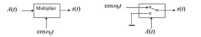
Figure 1. ASK modulate process
There are two ways of demodulation: coherent demodulation and incoherent demodulation. As shown in the Fig. 2.
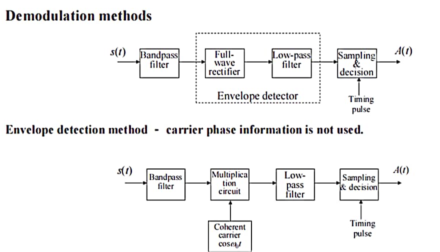
Figure 2. ASK demodulation process
\( P(f)=\frac{1}{4}[{P_{s}}(f+{f_{c}})+{P_{s}}(f-{f_{c}})] \) (2)
This is the power spectral density of the 2 ASK, \( P(f) \) is power spectral density of s(t) , \( {P_{s}} \) (f) is power spectral density of A(t). The above is the formula for conveying "0" and conveying "1" with the same probability.
\( {P_{e}}=\frac{1}{2}erfc(\sqrt[]{\frac{r}{4}}) \) (3)
\( {P_{e}}=\frac{1}{2}{e^{\frac{-r}{4}}} \) (4)
This is the bit error rate of coherent demodulation and noncoherent demodulation, r is SNR(r= \( \frac{{α^{2}}}{2{σ^{2}}} \) ), \( \frac{{α^{2}}}{2} \) is Signal power for the demodulator input, \( {σ^{2}} \) is Noise power at the demodulator input. \( \)
3.2. Principle and performance of the FSK
In binary digital modulation, the frequency of the sinusoidal carrier varies between f1 and f2 with the binary baseband signal, resulting in a binary frequency shift keying signal (2FSK signal) [6]. When the symbol "1" is sent, it corresponds to the carrier frequency f1, and when the symbol "0" is sent, it corresponds to the carrier frequency f2.
\( {e_{2FSK}}(t)=\begin{cases} \begin{array}{c} Acos({ω_{1}}+{θ_{0}}), When the value is set to 1 \\ Acos({ω_{2}}+{θ_{1}}), When the value is set to 0 \end{array} \end{cases} \) (5)
This is the expression of 2FSK in the time domain, \( {e_{2FSK}} \) is the expression of the 2 FSK time domain equation function, \( {ω_{1}},{ω_{2}} \) is the different modulated carrier frequencies, \( {θ_{0}},{θ_{1}} \) is different phases.The bandwidth of this digitally modulated signal is (| \( {f_{2}}-{f_{1}} \) |+2 \( {f_{s}} \) ) times the transmission rate of the symbol,That is means that the frequency band utilization of 2FSK is \( \frac{1}{(|{f_{2}}-{f_{1}}|+2{f_{s}})} \) ,Signal generation can be modulated by analog phase multiplication and digital keying. As shown in the Fig. 3.
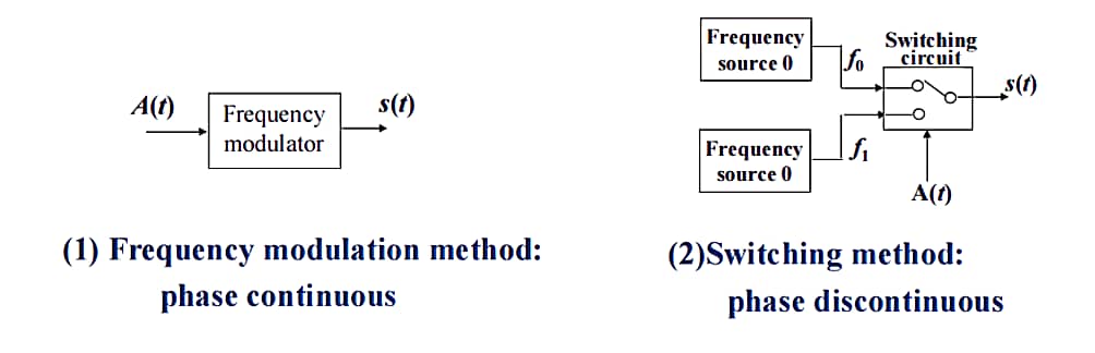
Figure 3. FSK modulate process
The signal can be demodulated by coherent demodulation, incoherent demodulation, zero-crossing detection, and differential detection. As shown in the Fig. 4 and Fig. 5.
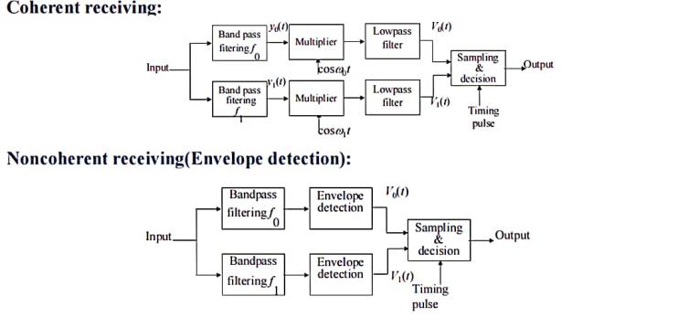
Figure 4. FSK demodulation process
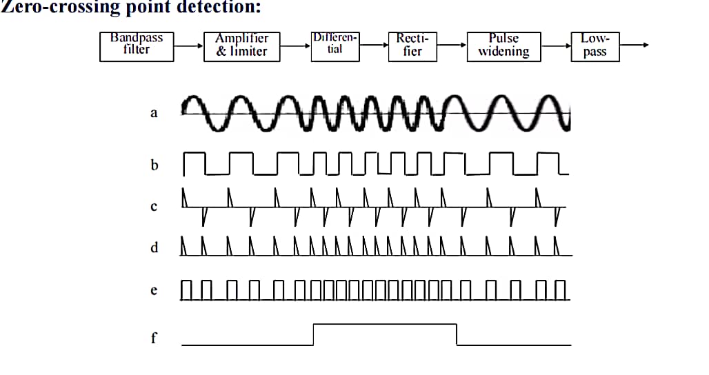
Figure 5. Zero-crossing detector
\( {P_{2FSK}}(f)=\frac{1}{4}[{P_{{s_{1}}}}(f-{f_{1}})+{P_{{s_{1}}}}(f+{f_{1}} \) )]+ \( \frac{1}{4}[{P_{{s_{2}}}}(f-{f_{1}})+{P_{{s_{2}}}}(f+{f_{1}} \) )] (6)
This is the power spectral density function of 2FSK digital modulation,The symbol sequence of 2FSK signal produced by the switching method can be regarded as the superposition of two 2ASK signals with different frequencies. \( P(f) \) is power spectral density of s(t), \( {P_{{s_{1}}}} \) is the power spectral density of the first ASK signal A(t) and is the power spectral density of the second FSK signal A(t).The above is the formula for conveying "0" and conveying "1" with the same probability.
\( {P_{e}}=\frac{1}{2}erfc(\sqrt[]{\frac{r}{2}}) \) (7)
\( {P_{e}}=\frac{1}{2}{e^{\frac{-r}{2}}} \) (8)
This is the bit error rate of coherent demodulation and noncoherent demodulation. \( \) Coherent detection and envelope detection have similar bit error rates in the case of large signal and noise. Because envelope detection is simpler and cheaper, it is being used more widely.
3.3. Performance of DPSK principle
PSK is the most basic and most commonly used digital modulation mode, and its most basic feature is that the amplitude and frequency are generally unchanged, and the base band digital signal is transmitted and distinguished by the phase change of the transmitted carrier [7]. The waveforms of PSK are roughly divided into four types:
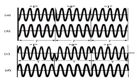
Figure 6. The waveforms of PSK
Fig. 6a and Fig. 6c is discontinuous phase, there is integer number of carrier periods on a symbol; Fig. 6b and Fig. 6d is continuous phase, The number of carrier periods in a symbol is one half period larger than integer number of periods. PSK transmits signal by distinguishing levels by different phases. The initial phase depend on what signal they will transmission, it clouds from \( {0^{°}} \) to \( {90^{°}} \) or something. There common Use the binary baseband NRZ bipolar rectangular pulse A(t) to multiply the carrier or use the baseband signal to control a switching circuit, and the switching circuit selects the input signals to get PSK signal. As shown in the Fig. 7 and Fig. 8.
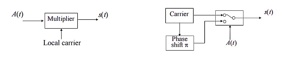
Figure 7. PSK modulate process
The demodulation of PSK can only use the coherent demodulation technique.
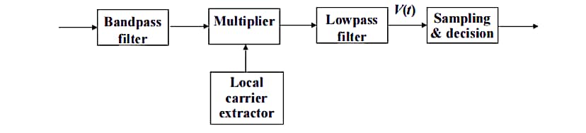
Figure 8. PSK demodulation process
This demodulation has some drawbacks, for one thing, the phase of the local carrier is difficult to determine. This results in phase ambiguity and channel instability in the frequency divider. The second is the possibility of a signal with a long continuous sinusoidal waveform, unable to distinguish between the start and end of the reception at the receiver. Because PSK has advantages and disadvantages that ASK and FSK do not have, it is difficult to use but innovative. DPSK solves this problem perfectly [8]. For DPSK signals, the initial phase 0° and 180° are usually used to represent the binary "1" and "0" of the digital base band signal, respectively. Compared with PSK, although the performance is slightly lower, but easier to achieve, it can be formed by converting the absolute code {an} into the relative code {bn}, and then the relative code {bn} through the absolute phase shift. The transformation relationship between absolute code {an} and relative code {bn} is an "xOR" logical relationship. As shown in the Fig. 9.
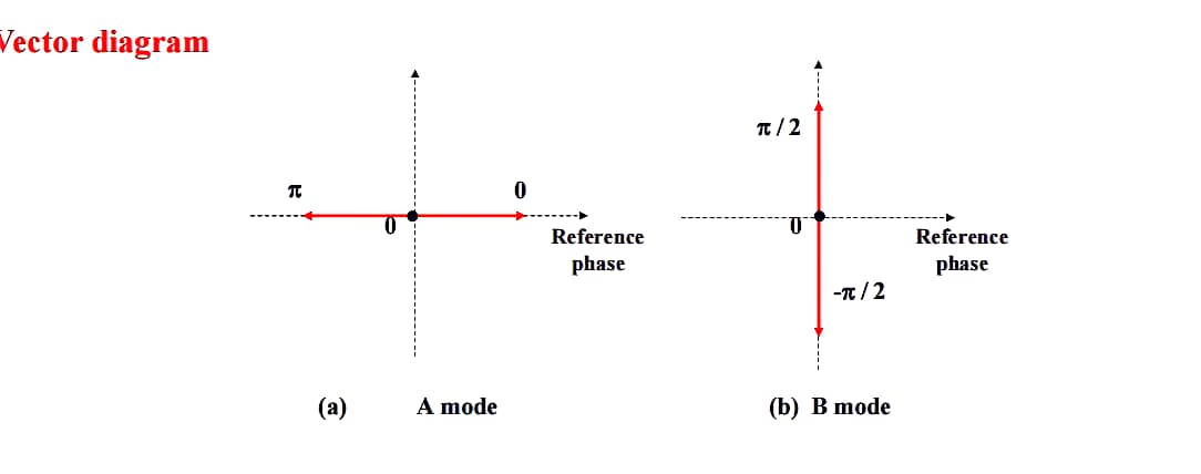
Figure 9. DPSK transformation relationship
DPSK has two modes: A mode and B mode.A mode is not perfect because it may have continue sinusoidal signal for long time.B mode make sure that different signals will cause difference phases.
\( {e_{2PSK}}(t)=\begin{cases} \begin{array}{c} Acos{ω_{c}}t, The sending probability is P \\ -Acos{ω_{c}}t, The sending probability is 1-P \end{array} \end{cases} \) (9)
This is the time domain expression of DPSK signal, \( {e_{2PSK}}(t) \) is function of 2PSK in time domain,A is the signal level.The bandwidth of.2DPSK is twice the transmission bit rate, that is, the band utilization of this digital modulation is 50%. Signal generation is generally through code transformation with analog phase multiplication or code transformation with digital keying method. As shown in the Fig. 10.
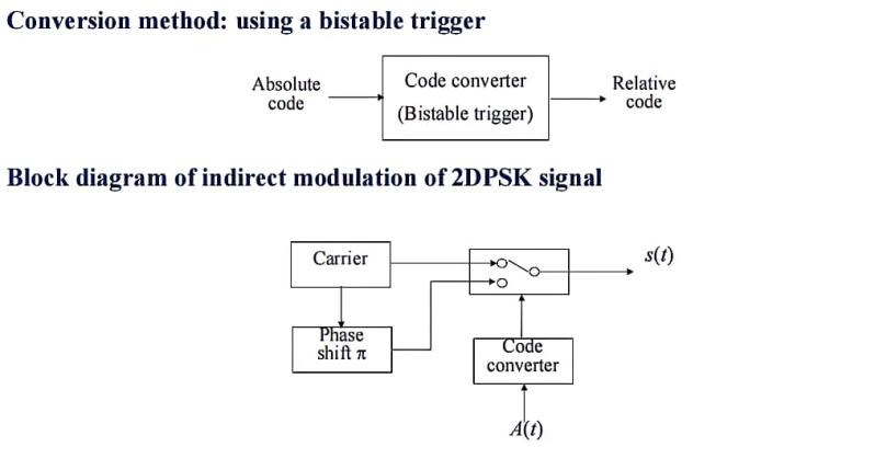
Figure 10. DPSK modulate process
Signal demodulation generally uses coherent demodulation and code inverse transformation method or differential coherent demodulation method. As shown in the Fig. 11 and Fig. 12.
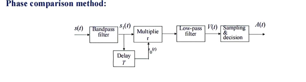
Figure 11. Phase comparison method
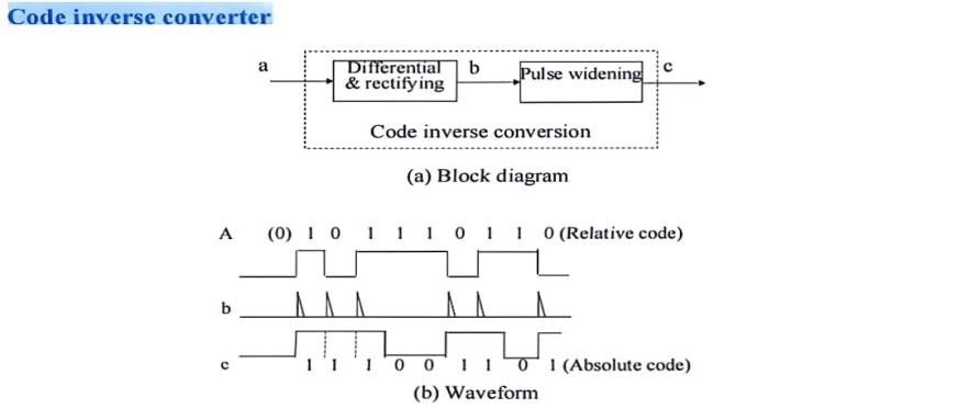
Figure 12. Coherent demodulation and code inverse
\( {P_{2PSK}}(f)=\frac{{T_{s}}}{4}[{|\frac{sinπ(f+{f_{c}}){T_{s}}}{π(f+{f_{c}}){T_{s}}}|^{2}}+{|\frac{sinπ(f-{f_{c}}){T_{s}}}{π(f-{f_{c}}){T_{s}}}|^{2}}] \) (10)
This is the power spectral density of the 2 DPSK, \( {P_{2PSK}}(f) \) is power spectral density of s(t), \( {T_{s}} is \) period.
\( {P_{e}}=erfc(\sqrt[]{r}) \) (11)
\( {P_{e}}=\frac{1}{2}{e^{-r}} \) (12)
This is the bit error rate of coherent demodulation and noncoherent demodulation.
3.4. Comprehensive comparison
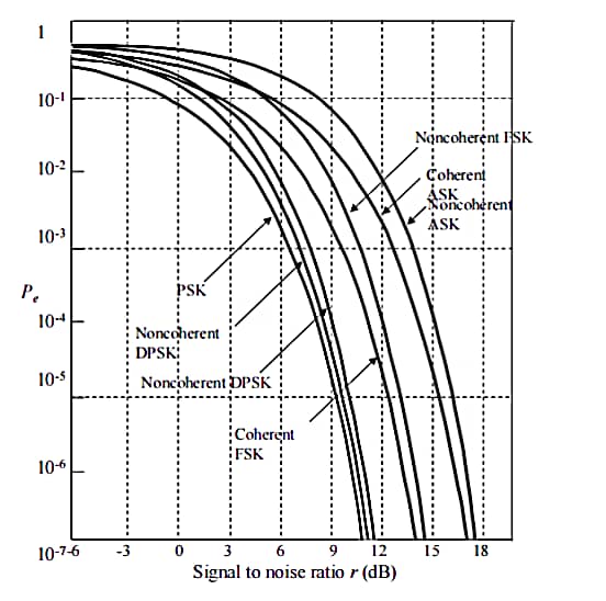
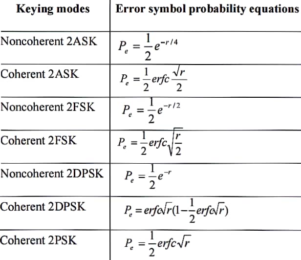
Figure 13. Bit error rate comparison
According to Fig. 13, we get that under the same bandwidth, the bit error rate of coherent demodulation is less than that of incoherent demodulation. Among different digital modulation, PSK has the smallest bit error rate, followed by DPSK. Under the same tuning method, the difference between ASK and FSK is about 3dB.
4. Discussion
DPSK is the combination of interpolation coding and PSK modulation. Consider a PSK modulated transmission system, before transmitting an information sequence, the sequence is interpolated and encoded, and a differential decoding is added after transmission to restore back to the digital information sequence, so that the combined modulation method is referred to as DPSK. DPSK is the information carried on the symbol change before and after, and then reproduced to the front and back phase change through PSK modulation. Based on the characteristics of DPSK, this transmission system is not afraid of reverse transmission during transmission, and DPSK can be received incoherently-differential detection.
4.1. 2DPSK modulation
On the one hand, only if the phase-shifting keying method is known to be absolute or relative, can the original information be correctly determined; On the other hand, a relative phase shift signal can be seen as a transformation of a sequence of digital information (absolute codes) into relative codes, and then an absolute phase shift according to the relative codes. This points out a method for modulating and demodulating 2DPSK signals by means of an absolute phase-shifting approach. The relative code here, that is, the differential code, is based on the adjacent symbol unchanged to represent the original digital information "0", and the adjacent symbol changes to represent the original digital information "1" The law is transformed by the absolute code.
There are two demodulation methods for demodulation of 2DPSK signals, one is the differential coherent coherent demodulation-code transformation method. This method is 2PSK demodulation plus differential decoding, and the block diagram is shown in Figure 5-27. The 2PSK demodulator restores the input 2DPSK signal to a relative code, and then converts the relative code into an absolute code by a differential decoder (code inverse converter) and outputs it. Demodulation, the other is coherent demodulation-code transformation. The latter is also known as the polarity comparison-code transformation method.
Differential coherent demodulation. It is composed of directly comparing the phase difference of the code elements before and after, so it is also called phase comparison method demodulation, and its principle diagram is shown in Figure 6 This method does not require a code converter or a special coherent carrier generator, so the device is relatively simple and practical. The output of the delay circuit in the figure acts as a reference carrier. The multiplier plays the role of phase comparison (phase reading).
4.2. The principle of GSM
GSM system structure, composed of four parts, mobile station MS, wireless base station subsystem BSS, switching network subsystem NSS and OMC operation and maintenance center. MS is the terminal, connected through the air interface and the wireless base station subsystem BSS, the wireless base station subsystem BSS includes the base station transceiver BTS and the base station controller BSC, responsible for wireless transmission and reception and wireless resource management. A group of BSS reports to MSC (Mobile Exchange Center) that MSC (Mobile Exchange Center) is connected to position registers such as HLR (Home Location Register), VLR (Guest Location Register) and AUC (Authentication Center) and EIR (Base Station Transceiver), which can know whether the user and the mobile phone are legitimate. It is also connected to the Operations Maintenance Center (OMC), the public switched telephone network (PSTN).
4.3. Application of GSM
Frequency multiplexing technology for a mobile communication system, the number of users in the same range is sometimes large, and the frequency resources used for communication are limited, which may not be able to meet the needs of many users to communicate at the same time, so it is necessary to reasonably reuse frequency resources. In the mobile communication system, frequency multiplexing is achieved by dividing a large range of communication coverage area into thousands of small communication areas, in each cell, limited users and the system of this cell in part of the available frequency band for multiple access communication, users adjacent to the cell can only use different frequency bands, and users who are not adjacent to the cell can reuse the same frequency band. In this way, a large area is divided into many small areas, each cell is shaped like a hexagon, so the mobile communication system is also called "cellular system". The frequency bands allowed to be used in adjacent cells are different, so when the mobile phone moves from one cell to another cell in communication, it must be controlled by the system for cross-zone switching. At the same time, because the location of the mobile phone often moves, the mobile phone must report its location to the system in time so that the system can find the mobile phone at any time.
5. Conclusion
This essay summarizes different methods of modulations, specifically emphasizes Differential Phase Shift Keying (DPSK) system with respect to its histories, developement, principals, working mechanisms, applications, as well as comparisons over to other major kinds of modulations from performance perspectives.
5.1. Working mechanism and comparisons to other major modulation systems
DPSK is a type of phase modulation used to transmit data through altering the carrier's wave's phase. In DPSK modulation, the phase of the modulated signal would be shifted relative to the signal being sent in the previous element. Such system does not require a sophisticated demodulation circuity and is typically less susceptible to random changes in the transmitted waveform, which may potentially be more reliable of transmitting various data.
When compared to other modulations such as FSK, DPSK modulation has a smaller overall error bit rate, a better immunity of noises, uses less bandwidth, a lower construction cost which would greately reduce the pressure in certain areas as well as a smaller overall error bit rate when compared against to FSK and ASK digital modulations under the same bandwidth.
When compared to Amplitude Shift Keying, ASK modulation has a lower overall power efficiency and is typically utilized in Wireless based stations, home automation devices, tire pressuring monitoring systems and so on.
On top of that, ASK system is also susceptible to noise interference which could potentially lead to a loss of transmissions during the process.
Furthermore, ASK system also has a higher error bit rate compared to DPSK system under the same bandwidth.
5.2. Further division of DPSK modulation system
DPSK modulation can further be divided into various different systems, which all differ considerably from Q values, error bit rates, distortion rates as well as approximate effective range [9].
For example, CSRZ-DPSK modulation has a higher overall Q value when compared against to RZ-DPSK as the transmission distance goes on, which will have a lower distortion rate. However, a lower distortion rate would therefore require a more sophisticated calculation system and thus becomes more time consuming and might also increase the overall construction cost.
5.3. Disadvantages
Despite all the advantages, DPSK modulation has a higher interference noise during the process, which may lead to a higher bit error rate.
Besides, the modulation adapts 2 bits in order to work. As a result, an error in the primary bit would therefore carries the bit to the other bit as well as consecutive error spread.
5.4. Recommendations in the future development
• Future 5G development using DPSK system
DPSK system is currently being widely adapted in wireless communications of LANs, RFID, Bluetooth ands so on.
Compared to DPSK modulation, Quality Amplitude Modulation (QAM) is currently more common used in the development. Despite this, DPSK still has its value in certain application scenarios. The following are several possible applications and explanations of DPSK in 5G:
1): A robust low-power transmission
In certain cases, particularly in remote or poorly covered areas, it may require a modulation method that is more robust but a lower data rate. DPSK modulation can provide a better performance in such circumstances as it has a better tolerance for certain types of noise and interference in the channel.
2): Internet of Things (IoT) devices
Many IoT devices require operation at low power and low data rates. For these devices, DPSK can provide them with a simple and robust modulation solution.
3): Satellite communication
Although 5G is mainly ground communication technology, with the development of Non-Territorial Network (NTN), 5G is gradually being used for satellite communication. In long-distance satellite communication, DPSK may become a valuable choice due to its robustness.
4): Enhanced Machine Class Communication (eMTC)
eMTC is designed to support low-cost, low data rate, and delay insensitive applications. In these applications, DPSK can provide simple and effective solutions.
Overall, although more superior modulation techniques are being adapted for the development of 5G technology, DPSK still managed to hold a significant value and role in certain specific applications and scenarios.
References
[1]. J. Leuthold, Optical Communication Systems. (2008). Institute of High-Frequency and Quantum Electronics (IHQ).
[2]. X. Wei, J. Leuthold, Ch. Dorrer, D.M. Gill, and X. Liu, Chirp Reduction of π/2 Alternate-Phase Pulses by Optical Filtering (2005) Anaheim (USA)
[3]. A.H. Gnauck, and P.J. Winzer, Optical Phase-Shift-Keyed Transmission (2005) Journal of Lightwave Technol.
[4]. J. H. Sinsky, A. Adamiecki, A. Gnauck, C. Burrus, J. Leuthold, O. Wohlgemuth, 42-7-Gb/s integrated balanced optical front end with record sensitivity (2003) Atlanta
[5]. Kong Lingbin. Li Ying, et al.(2022) .Design of 2ASK Digital Frequency Band Transmission System.2-3
[6]. Qu Weizhe. (2022).Simulation analysis technology of digital communication signal based on PSK modulation.2-3
[7]. Wang Jian. (2023). Research into the countermeasure effect of jamming to FSK modulation system..Academy of Military Sciences.2-4
[8]. Fan Changxin, (2012) Principles of Communications Third Edition.Bei Jing
[9]. Jin Huang, Research on the Nonlinear Effects of DPSK Optical Fiber Communication Systems, 2012, Nanjing University of Posts and Communications.
Cite this article
Liang,J.;You,Y.;Ma,R.;Gao,M. (2024). Advantages and development prospects of DPSK digital modulation. Applied and Computational Engineering,79,66-76.
Data availability
The datasets used and/or analyzed during the current study will be available from the authors upon reasonable request.
Disclaimer/Publisher's Note
The statements, opinions and data contained in all publications are solely those of the individual author(s) and contributor(s) and not of EWA Publishing and/or the editor(s). EWA Publishing and/or the editor(s) disclaim responsibility for any injury to people or property resulting from any ideas, methods, instructions or products referred to in the content.
About volume
Volume title: Proceedings of the 4th International Conference on Signal Processing and Machine Learning
© 2024 by the author(s). Licensee EWA Publishing, Oxford, UK. This article is an open access article distributed under the terms and
conditions of the Creative Commons Attribution (CC BY) license. Authors who
publish this series agree to the following terms:
1. Authors retain copyright and grant the series right of first publication with the work simultaneously licensed under a Creative Commons
Attribution License that allows others to share the work with an acknowledgment of the work's authorship and initial publication in this
series.
2. Authors are able to enter into separate, additional contractual arrangements for the non-exclusive distribution of the series's published
version of the work (e.g., post it to an institutional repository or publish it in a book), with an acknowledgment of its initial
publication in this series.
3. Authors are permitted and encouraged to post their work online (e.g., in institutional repositories or on their website) prior to and
during the submission process, as it can lead to productive exchanges, as well as earlier and greater citation of published work (See
Open access policy for details).
References
[1]. J. Leuthold, Optical Communication Systems. (2008). Institute of High-Frequency and Quantum Electronics (IHQ).
[2]. X. Wei, J. Leuthold, Ch. Dorrer, D.M. Gill, and X. Liu, Chirp Reduction of π/2 Alternate-Phase Pulses by Optical Filtering (2005) Anaheim (USA)
[3]. A.H. Gnauck, and P.J. Winzer, Optical Phase-Shift-Keyed Transmission (2005) Journal of Lightwave Technol.
[4]. J. H. Sinsky, A. Adamiecki, A. Gnauck, C. Burrus, J. Leuthold, O. Wohlgemuth, 42-7-Gb/s integrated balanced optical front end with record sensitivity (2003) Atlanta
[5]. Kong Lingbin. Li Ying, et al.(2022) .Design of 2ASK Digital Frequency Band Transmission System.2-3
[6]. Qu Weizhe. (2022).Simulation analysis technology of digital communication signal based on PSK modulation.2-3
[7]. Wang Jian. (2023). Research into the countermeasure effect of jamming to FSK modulation system..Academy of Military Sciences.2-4
[8]. Fan Changxin, (2012) Principles of Communications Third Edition.Bei Jing
[9]. Jin Huang, Research on the Nonlinear Effects of DPSK Optical Fiber Communication Systems, 2012, Nanjing University of Posts and Communications.