


1. Introduction
Formula 1 World Championship (FIA Formula 1 World Championship, referred to as F1) is the highest level of the annual series of track racing held by the International Motor Sport Federation (FIA), is the highest level of motor racing in the world today. Formula l world championship (“ F1 “). The formula here has nothing to do with mathematics it means “rules and restrictions”, because the Formula 1 race has to follow the specifications and rules formulated by the International Automobile Association (FIA) to build cars and race, and all participating teams must comply with this set of strict guidelines as the formula [1]. This paper mainly studies why F1 cars have strong downforce and high-tech products at extremely high speeds. According to the current condition of F1 cars and competition regulations, many teams still face problem caused by insufficient downforce of cars, so they can not get higher points to expand the popularity of the team. In this paper, Bernoulli’s principle and the principle of lift generation will be applied to explore the answer to the question. The significance of this study is that people who love F1 racing can have a better understanding of racing and better promote this sport.
2. The Problems Facing F1 Cars
As people all know, when a car is driving at a high speed, it will face great wind resistance to hinder the movement of the vehicle. But in Formula 1, when faced with corners of more than 200 yards an hour, the car still maintains a strong brake to get through the corners quickly.
Air is mainly composed of nitrogen, oxygen, noble gases (such as helium, neon, argon, krypton, xenon, and radon), carbon dioxide, and other substances (such as water vapor, trace amounts of hydrogen, ozone, nitrous oxide, methane, and dust) When a gas passes through the surface of a shaped object, some particles are attached to the surface. So in relative motion, the layer of particles attached to the surface slows down, forming surface friction. Therefore, this paper can easily understand that fewer objects more in line with the flow of air are needed when the car is racing to reduce friction, so that the air is converted into a part of the power, and the speed of the car is continuously improved, causing minimal impact on the car.
When the airflow follows a curve (or changes direction), as long as it is thin, its motion does not change. However, when the curve has a certain shape, or suddenly changes direction. The airflow splits in two across the surface, but there is not enough energy to pass through the surface. This situation needs to be avoided because the critical layer is so thick that the air flow in front of it slows down and blocks the air flow behind it like a solid surface. So a pointed object can only exert more resistance through the air flow [2].
3. Aerodynamics
Let’s meet and talk about what is aerodynamics. Aerodynamic roughness is an important aspect of modern fluid mechanics
The concept is a geometric height at which the wind speed is equal to zero, which characterizes the relationship between the surface and the interaction between the atmosphere reflecting the weakening effect of the surface on wind speed and its impact on wind and sand activities. It is also an important parameter in fluid dynamics and atmospheric boundary layer theory research and plays an extremely important role in wind and sand science, fluid dynamics, and atmospheric science. Aerodynamic roughness
Research is one of the key factors in gaining a deeper understanding of the mechanisms underlying sand and wind activities on different beds, as well as in preventing and controlling sand and wind hazards. Therefore, since half a century ago
Bagnold established the physics of sandstorms, which has attracted the keen attention of scholars both domestically and internationally and has achieved important research results. Aerodynamics Roughness has been widely used to characterize the aerodynamic properties of various surface types, such as sandy surfaces, vegetation-covered surfaces, ice and snow surfaces, and sea surfaces [3]. Therefore, understanding the origin of the concept of aerodynamic roughness, understanding the physical and practical significance of aerodynamic roughness, and mastering the current research status and trends of aerodynamic roughness can accelerate air quality
The study of dynamic roughness has important guiding significance. The wind tunnel power system is driven by a DC motor with a power of 620kW, the fan system is composed of 9 glass fiber reinforced plastic blades, and the speed control system adopts Siemens 6RA7090 DC speed control device. Wind velocity control, data acquisition and test monitoring are basically all integrated in the main control room to achieve fully automated computer system control [4]. Using the most advanced wind tunnel detection equipment, you can better feel the passage of air. The F1 IN SCHOOLS competition was established in 2004 to develop students interest towards science, technology, engineering and mathematics (STEM) in the secondary school phase. The application of aerodynamics is one of the important aspects studied during this phase [5]. The computational fluid dynamics method is applied to optimize the shape design of F1 car to improve its aerodynamic characteristics[6].
4. Using Aerodynamic Components
Throughout the history of Formula 1, there have been many practical examples of the constant evolution of racing technology to address grip issues and improve overall performance. A notable example is the era of ground-effect vehicles in the late 1970s and early 1980s. Teams such as Lotus and Ground Effects have used ground effect equipment to increase the speed of air generated under the vehicle through a special design of the floor and the introduction of side tunnels, creating tremendous bottom pressure and significantly improving adhesion.
The Lotus 79 and 80 models were typical of the time, and they created effective ground effects through the clever design of the floor so that the air created a strong negative pressure under the car. This technological breakthrough makes the vehicle extremely stable when driving on corners, while improving overall speed and performance.
However, ground-effect vehicles also bring safety hazards, especially the sudden loss of control that can occur when the bottom plate fails. This has led to changes in technical regulations that limit the design of ground-effect vehicles. Over time, the team has adopted other advanced technologies such as adjustable aerodynamics packages, more advanced tire technology, and advanced suspension systems to balance grip with safety.
It is a team secret that this paper cannot see the chassis of an F1 car, even after it has been retired.
In the process of driving, F1 cars will produce a flow of air throughout the car, which can also determine the longitudinal load of the main key. At the same time, the airflow passing through the radiator from the side is equally important, as this airflow is mainly used for engine cooling. Therefore, it must be introduced from the radiator inlet and then exported from the exhaust port at the rear of the vehicle. Moreover, it must not interfere with the airflow flowing above the vehicle to avoid the turbulence that may affect the stability of the vehicle during operation; In addition to the airflow above and on the side of the vehicle, what is more important is the airflow passing through the chassis, because this airflow is not only an important condition for downward pressure, but also accounts for more than 45% of the total airflow above and on the side of the vehicle.[4]So in order to improve the aerodynamic performance of the underside of the car, the team engineers installed the deflector under the rear of the car, one of the most important aerodynamic packages.
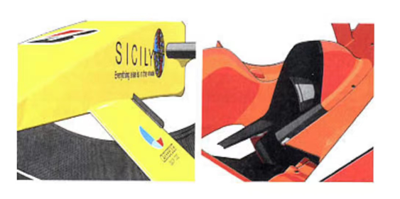
Figure 1. Fw24Diffuser [7]
Regarding the design of the bottom of the car body, the bottom plate in the center of the car body must follow the rules of the competition, so the differences between different teams of racing cars are not too significant[8], but there is a significant difference in the design of the center and sides of the Diffuser located below the rear of the car, with the height of the vertical spoiler and guide chamber being the most significant differences[9] Due to the role of the Di f fuser in drawing a rest for the aerodynamic forces under the car, it is not difficult to imagine the differences in the design of Diffuser shapes among different racing teams. Taking Ferrari and Williams, the two most competitive teams in the current competition, as examples, this paper will compare them. In fact, these two teams have significant differences in the concept of detailed design. However, in addition, there are also many similarities between the two teams, and as each race progresses, there seems to be increasing similarities between the two teams. But this is only one part of the Formula 1 car, because every part of the Formula 1 car is aerodynamically studied to the extreme to be the fastest car in the world.
5. Racing Driver and Team Communication
Riedel has been working closely with the FIA since 1993, providing radio and communication systems products and services throughout the world during the March to November Formula 1 races [10]. After understanding the structure of the car, there is another or indispensable item, that is, what to communicate, because when the driver is in the car, all he can see is the track, the opponent and the weather. When this paper watch F1 cars, this paper can’t see the picture of the driver’s contact with the team, but from the promotional videos reported by the major teams, it is not difficult to see the importance of communication, because the driver will face a variety of emergencies, which is unpredictable by engineers, so whenever there is any sudden situation, the driver needs to report to the team in time and communicate with the coach. Formula One (F1) racing drivers and teams heavily rely on communication and data gathering to enhance performance.
The importance of using fully deformable tyres in wind tunnel testing to accurately simulate the wheel wake of a grand prix car. The high vertical loads and camber levels used in F1 racing make rigid tyres unsuitable for such simulations [11]. In the Formula One World Championship (F1), single-seater cars can easily exceed 300 km/h, and can also have extremely high speeds when entering corners and withstand amazing G-forces. Tire World Network learned that Pirelli, as the exclusive tire supplier for F1 events, had been cooperating until 2019. The new requirements put forward by the FIA pose a new challenge for it [12].
Pirelli’s Formula 1 tyre range consists of two types.
P Zero tyres, bare heads for dry asphalt, available in five different formulations.
Cinturato tyres, are two types, Cinturato green wet tyres for slightly wet tracks and Cinturato blue full rain tyres for heavy rain scenarios. P Zero tyres and Cinturato tyres will be present at every Grand Prix.
The five models, defined as C1, C2, C3, C4 and C5, represent five different formulations, the hardest being C1 and the softest being C5.
Not all five formula tyres are brought to every race, a “nominated combination” is used each race weekend. The three selected formulations are the P Zero white hard tyre, P Zero yellow neutral tyre and P Zero Red soft tyre for each race.
Based on the different characteristics and layout of each track, three recipes are selected at a time as the nominated combination.
Three commonly used models that this paper often see on F1 tracks:
C2 hard tyre
C3 neutral fetus
C4 soft tyre
Choose the average strategy according to the team strategy.
In the field of tire technology, the formulation and structural design of rubber composites are of great importance. Racing tyres use a highly specialised rubber mixture combined with special fibre-reinforced materials to achieve optimal grip performance at high speeds. In addition, by fine-tuning the inner and outer friction properties of the tires, tire pressure and temperature distribution, racing teams can achieve optimal adhesion at different parts of the track. Nitrogen has long been used to fill tires because of the high pressure required. The advantages of using nitrogen gas inflation include: (1) improving the stability and comfort of tyre driving. (2) Prevent tyre blowouts and lack of air during driving. (3) Extend the service life of tyres. Nitrogen is an almost inert diatomic gas with extremely inactive chemical properties. The gas molecules are larger than oxygen molecules and are less prone to thermal expansion and contraction. Its deformation amplitude is small, and its penetration rate into the tyre wall is about 30-40% slower than air. It can maintain stable tyre pressure, improve tyre driving stability, and ensure driving comfort [13].
6. Conclusion
Formula 1 will continue to be the world’s obsession. Formula 1’s approach to grip involves complex ground effects, tyre technology, suspension tuning and aerodynamic design, creating a multi-layered, interactive system that offers the possibility of exceptional performance in extreme conditions. This paper cannot draw on various references in the cited literature, and the explanation of aerodynamics is not detailed enough, only superficial explanation and translation. Formula 1 cars show us the most advanced technology, the most powerful team support and the most important drive future research may be more inclined to the relationship between inclination and air, to further study and improve the performance of the car. This paper cannot draw on various references in the cited literature, and the explanation about aerodynamics is not detailed enough, only a superficial explanation and translation.
References
[1]. Hu Lianrong. New knowledge of F1 racing [J]. Knowledge is Power,2004(9):8-9.
[2]. Tao Song with Rui Hu - The Application of aerodynamics in F1 cars, Article No. 2095-8234 (2014) 04-0093-04
[3]. Xiaoping Deng with Zhibao Dong-Physical and practical significance of aerodynamic roughness-Article No.1000-694X(2003)04-0337-10
[4]. Agathangelou B , Gascoyne M .Aerodynamic Design Considerations of a Formula 1 Racing Car[C]//International Congress & Exposition.1998.DOI:10.4271/980399.
[5]. Sawley M L , Richter R .Numerical simulation of the flow around a Formula 1 racing car[J].Epfl Supercomputing Review, 1997.
[6]. Issakhanian E , Lo K P , Axeriocilies J ,et al.Comparison of PIV and CFD for a Formula 1 Racing Car Front Tire[J].American Physical Society, 2008.DOI:http://dx.doi.org/.
[7]. Faiz Paturrahman, M., Radzi Abu Mansor, M., Harun, Z., & Anas Mohd Sabri, M. (2018). Study on the Modification Effect of Side Pot And Diffuser to the Aerodynamics of the F1 IN SCHOOLS Car. International Journal of Engineering & Technology, 7(3.17), 123-128. https://doi.org/10.14419/ijet.v7i3.17.16635
[8]. Journal of Wuhan Institute of Physical Education, No. 3, 2005 1 Ma Yong, Zheng Weitao, Han Jiurui, Wuhan
[9]. Max,Schindlmeier,Michael,et al.Self-developed Planetary Gears for a Formula Student Racing Car[J].Automobiltechnische Zeitschrift, 2016.
[10]. Max,Schindlmeier,Michael,et al.Self-developed Planetary Gears for a Formula Student Racing Car[J].Automobiltechnische Zeitschrift, 2016.
[11]. Pan Xiaowei; Valley Zhengqi; He Yibin; Wang Yiping Source journal: Automotive Engineering, No. 3, 2009
[12]. Bray B .’Why Would Anyone Want Anything but a Smart Car?’ ; the 5-Minute Interview David Coulthard Formula 1 Racing Driver[J].[2024-05-17].
[13]. Gilchrist M D , Curley L J .Manufacturing and ultimate mechanical performance of carbon fibre-reinforced epoxy composite suspension push-rods for a Formula 1 racing car[J].Blackwell Science Ltd, 1999(1).DOI:10.1046/J.1460-2695.1999.00133.X.
Cite this article
Lian,Z. (2024). The technology of Formula 1 racing car . Applied and Computational Engineering,70,156-160.
Data availability
The datasets used and/or analyzed during the current study will be available from the authors upon reasonable request.
Disclaimer/Publisher's Note
The statements, opinions and data contained in all publications are solely those of the individual author(s) and contributor(s) and not of EWA Publishing and/or the editor(s). EWA Publishing and/or the editor(s) disclaim responsibility for any injury to people or property resulting from any ideas, methods, instructions or products referred to in the content.
About volume
Volume title: Proceedings of the 2nd International Conference on Functional Materials and Civil Engineering
© 2024 by the author(s). Licensee EWA Publishing, Oxford, UK. This article is an open access article distributed under the terms and
conditions of the Creative Commons Attribution (CC BY) license. Authors who
publish this series agree to the following terms:
1. Authors retain copyright and grant the series right of first publication with the work simultaneously licensed under a Creative Commons
Attribution License that allows others to share the work with an acknowledgment of the work's authorship and initial publication in this
series.
2. Authors are able to enter into separate, additional contractual arrangements for the non-exclusive distribution of the series's published
version of the work (e.g., post it to an institutional repository or publish it in a book), with an acknowledgment of its initial
publication in this series.
3. Authors are permitted and encouraged to post their work online (e.g., in institutional repositories or on their website) prior to and
during the submission process, as it can lead to productive exchanges, as well as earlier and greater citation of published work (See
Open access policy for details).
References
[1]. Hu Lianrong. New knowledge of F1 racing [J]. Knowledge is Power,2004(9):8-9.
[2]. Tao Song with Rui Hu - The Application of aerodynamics in F1 cars, Article No. 2095-8234 (2014) 04-0093-04
[3]. Xiaoping Deng with Zhibao Dong-Physical and practical significance of aerodynamic roughness-Article No.1000-694X(2003)04-0337-10
[4]. Agathangelou B , Gascoyne M .Aerodynamic Design Considerations of a Formula 1 Racing Car[C]//International Congress & Exposition.1998.DOI:10.4271/980399.
[5]. Sawley M L , Richter R .Numerical simulation of the flow around a Formula 1 racing car[J].Epfl Supercomputing Review, 1997.
[6]. Issakhanian E , Lo K P , Axeriocilies J ,et al.Comparison of PIV and CFD for a Formula 1 Racing Car Front Tire[J].American Physical Society, 2008.DOI:http://dx.doi.org/.
[7]. Faiz Paturrahman, M., Radzi Abu Mansor, M., Harun, Z., & Anas Mohd Sabri, M. (2018). Study on the Modification Effect of Side Pot And Diffuser to the Aerodynamics of the F1 IN SCHOOLS Car. International Journal of Engineering & Technology, 7(3.17), 123-128. https://doi.org/10.14419/ijet.v7i3.17.16635
[8]. Journal of Wuhan Institute of Physical Education, No. 3, 2005 1 Ma Yong, Zheng Weitao, Han Jiurui, Wuhan
[9]. Max,Schindlmeier,Michael,et al.Self-developed Planetary Gears for a Formula Student Racing Car[J].Automobiltechnische Zeitschrift, 2016.
[10]. Max,Schindlmeier,Michael,et al.Self-developed Planetary Gears for a Formula Student Racing Car[J].Automobiltechnische Zeitschrift, 2016.
[11]. Pan Xiaowei; Valley Zhengqi; He Yibin; Wang Yiping Source journal: Automotive Engineering, No. 3, 2009
[12]. Bray B .’Why Would Anyone Want Anything but a Smart Car?’ ; the 5-Minute Interview David Coulthard Formula 1 Racing Driver[J].[2024-05-17].
[13]. Gilchrist M D , Curley L J .Manufacturing and ultimate mechanical performance of carbon fibre-reinforced epoxy composite suspension push-rods for a Formula 1 racing car[J].Blackwell Science Ltd, 1999(1).DOI:10.1046/J.1460-2695.1999.00133.X.