


1. Introduction
Vehicles are an important and common mode of transportation used worldwide, but vehicle usage contributes to large greenhouse ga emissions. Challenges in controlling these greenhouse gas emissions have led to strict regulations and competition for increased vehicle fuel economy. Due to this, automobile makers have a growing interest in fabricating lightweight vehicle designs. While weight reduction contributes to better vehicle performance such as increased braking effectiveness, vehicle handling, and passenger safety, it also contributes to reducing a vehicle’s fuel expenditures, thereby reducing the cost of operations as well as carbon emissions. An effective strategy to this problem would be utilizing new lightweight yet high-performing materials in automobile components as alternatives for conventional materials like steel [1].
Aluminum alloys consists of aluminum mixed with other alloying elements like lithium, zinc, manganese, copper, silicon, etc. Aluminum alloys are one of the most used materials in the automotive industry for their lightweight, high strength, ductility and high forgeability. This makes it an attractive material for automobile light-weighting applications, possibly replacing many conventional steels as aluminum is able to provide the same structural strength with much less weight while remaining relatively affordable. In addition, research conducted by Zhou [2], which includes a built prototype and computer simulations concludes that aluminum alloy is a safe and reliable material for car hood application. However, many alloy series especially from the 6xxx and 7xxx series are plagued with poor corrosion resistance which is made evident by previous research [3]. To resolve this issue, methods like anodizing and sealing have been immersion tested and proven to dramatically increase corrosion resistance as well as hardness in aluminum alloys [4].
Magnesium alloys are composed of magnesium with other elements added, the most widely used is magnesium aluminum alloy, followed by magnesium manganese alloy and magnesium zinc zirconium alloy. The appealing properties of magnesium alloys include their light weight, high strength, excellent castability, and machinability. It is mainly used in aviation, aerospace, transportation, chemical industry, and other industrial sectors. However, it is important to note that magnesium alloys also have limitations, such as limited formability, which restricts their industrial application. So, to solve such problems, many researchers have done investigations, for example, Zhang [5] utilized CALPHAD(Calculation of Phase Diagram) to design a crossover alloy, Al- 5.63Mg-5.43Zn-0.51Cu, which has ultra-high strength and acceptable elongation, Liu [6] refined grain size and depressed intergranular deformation simultaneously to design Mg-1Sb-1Mn-1Sn-0.2Zn which can achieve preeminent strength-ductility synergy through trace co-addition of Sn and Zn, Tian [7] invented an ultra-light Mg alloy with exceptional Young’s modulus and great strength.
Fiber reinforced composite materials are generally considered a lightweight, strong and environmentally friendly option to use in industrial design. They have applications in the aerospace and electronic parts industries [8]. Glass Fiber Reinforced Polymer (GFRP) and Carbon Fiber Reinforced Polymer (CFRP) are the most used composites. They can be manufactured using several processes, including compression molding, filament winding and resin transfer molding [9]. CFRPs have excellent mechanical properties, fatigue performance, and corrosion resistance while GFRPs are less durable but cheaper and easier to manufacture [10]. Replacing metal in certain parts of automotives with lower density composites would reduce the weight of the vehicle, reducing fuel consumption.
In this paper, the appropriate mechanical properties of different parts of the automobile will be taken into consideration. The main aspects that will be discussed are resistivity to corrosion, strength, fatigue and ease of processing. The lightweight materials of aluminum alloys, magnesium alloys, carbon fiber composites and glass fiber composites will be evaluated based on these properties. Appropriate materials will be presented for use in different car components.
2. Discussion
2.1. Aluminum Alloys
As a brief description, the widely recognized Aluminum association has divided aluminum alloys into categories for simplification– for example, material with the name “6xxx” stands for alloys in which magnesium and silicon are principal alloying elements while “5xxx” stands for alloys in which magnesium is the principal alloying element. As described by Figure 1, a distinctive feature regarding A6061 is its high forgeability, the ability for metals to undergo deformation without forming cracks. Aluminum alloys are used in all sorts of vehicles like trucks, airplanes, railroad cars, and automobiles for their high strength and low weight [11].
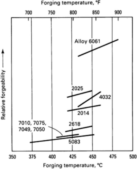
Figure 1. Forgeability and forging temperature of various aluminum alloys [11].
2.1.1. Strength
Aluminum alloys are already used widely within the automotive industry meaning its strength properties are well understood, however, optimizations can be made to maximize light-weighting without compromising safety. Further tests and analysis should be conducted to find out how exactly how much weight aluminum alloys can save and how it can impact safety. Aluminum alloy wheel rims have been experimented with by Loganathan [12] in a recent research paper. First, simulation models of the aluminum alloy wheel rim were constructed with SolidWorks, then analysis was performed using ANSYS academic 2021. Stresses on the wheel rim were collected in megapascals (MPa), while Factor of Safety (FOS) was also collected. The experiment also considered a multitude of factors affecting wheel rim strength–the rotational velocity, pressure acting on the wheel rim surface, and forces from acceleration. In addition, two different alloys were selected for the analysis: A6061 and AZ80(a magnesium alloy), with A6061 being the more common cheaper material and the latter one being higher in strength but more expensive [12].
Results from the ANSYS analysis (Table 2) show similar stress sustained for both A6061 and AZ80, however, AZ80 clearly has the higher FOS averaging at 4.09 while FOS provided for A6061 averages at 2.09. The study also shows that maximum reductions in weight is up to 58% aluminum alloy wheel rims tested without compromising safety parameters. Considering the cost of both materials coupled with low availability of magnesium, A6061 is clearly a much more affordable for manufacturing than compared to AZ80. [12] While A6061 may seem less safe in comparison to AZ80, studies of new nanocomposite materials which combines graphene with A6061 show promising results - Cast samples show a dramatic increase in tensile strength relative to the weight of graphene added according to Figure 2 [13]. It is also worth noting that this material’s susceptibility to fire damage causes major concern especially for ship manufacturers. A study conducted by Han [14] investigating aluminum alloy 6061 shows that yield stresses of fire exposed AA6061 reduced by around 70%, dropping from around 300 MPa to 88 MPa at 400°C, making it susceptible to deformation and failures in various applications. In automobile applications, fires may occur especially in accidents, structural failure will be a safety concern for passengers.
In summary, A6061 is a suitable replacement for conventional steel in lightweight automobile components–the weight of the wheel rim has been reduced by 58% without compromising safety with a FOS of 2.09. In addition, the material AZ80 is able to reach a FOS that is 2 higher than A6061 at 4.09, meaning even less material needs to be used to achieve the same FOS, reducing weight even further. However, it is more expensive and less commonly available than A6061.
Table 1. Comparison of AL 6061’s and AZ80’s equivalent stress and FOS analysis results from ANSYS [12]
S. No | AL 6061 | AZ80 | ||
Equivalent Stress (MPa) | FOS | Equivalent Stress (MPa) | FOS | |
SET 1: | Lug nuts | |||
1 | 92.5 | 1.56 | 91.45 | 3.00 |
2 | 110.62 | 1.35 | 111.36 | 2.46 |
3 | 76.67 | 1.89 | 70.13 | 3.92 |
SET 2: | Pitch Circle Diameter | |||
110 | 74.35 | 1.95 | 72.15 | 3.81 |
120 | 69.44 | 2.08 | 68.04 | 4.04 |
130 | 76.67 | 1.89 | 70.13 | 3.92 |
SET 3: | Thickness of the Rim | |||
5.5 | 69.05 | 2.09 | 68.141 | 4.03 |
5.75 | 69.02 | 2.1 | 68.23 | 4.03 |
6.0 | 67.49 | 2.14 | 66.72 | 4.1204.04 |
6.25 | 69.44 | 2.08 | 68.04 |
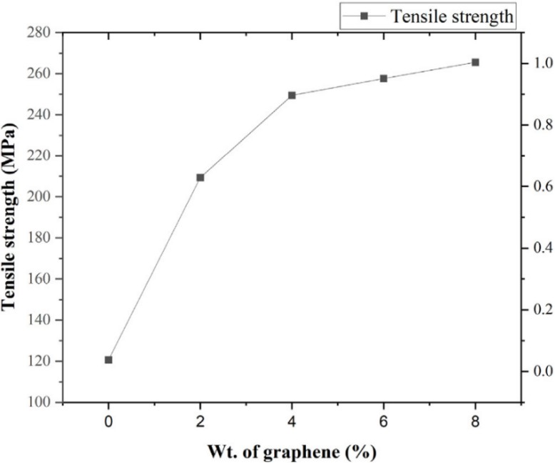
Figure 2. Tensile strength of material relative weight of graphene [13].
2.1.2. Processing difficulty
After aluminum alloys have been created, they must go through processing in order to be formed into desired shapes and sizes, this is important for automobile component manufacturing as easier and more effective processing likely means low cost and improved mechanical qualities. The most common types of Aluminum alloy processing methods include drilling, welding, stamping, forging, casting, heat treatment, and laser additive manufacturing (LAM) [13], [15-18]. However, these processing methods of aluminum alloys are often faced with many difficulties like its poor workability, low formidability, and brittleness. For example, a study by Cui [15]states that high strength alloys have a low laser absorption rate as many alloying elements are easy to burn, oxidize and crack under traditional LAM techniques like selective laser melting (SLM) or direct energy deposition (DED). As a result, forming and additive manufacturing technology for aluminum alloys has fallen behind when compared to other materials. This issue can be resolved by the newly introduced oscillating laser additive manufacturing (O-WLAM) technique. The experiment will be conducted on a piece of 10mm thick aluminum alloy 6061 acting as the substrate. Different oscillation patterns with the laser were explored in the experiment, such as circular oscillation, “∞” shape oscillation, “8” shape oscillation, and linear oscillation. Finally, heat treatment, another type of processing technique that would heat the material for a certain amount of time, was also given to the deposited samples to study its effects [15].
The study shows that a well-formed sample was produced via oscillating laser additive manufacturing. Figure 3 shows the non- oscillating pass had poor surface spread and flatness, while also requiring a larger heat input leading to undesirable severe heat buildup. Visually speaking, the circular and “∞”shape oscillation performed the best with no visual defects, producing a uniform finish, preventing defects like pores or cracks from forming. The study also shows that heat treatment at 530°C for 20 hours can improve tensile strength significantly. Figure 4 demonstrates this as the yield strength of As-deposited samples max out at around 270 MPa while heat-treated samples can reach 450 MPa [15].
In summary, the O-WLAM technique is a suitable solution to mitigate defects like cracks or pores, improving the workability of Aluminum alloys. The study also how heat treatment greatly improves yield strength of aluminum alloys. This is significant for the automotive industry as these methods would allow lightweight materials to be processed more effectively while improving their mechanical properties like yield strength.
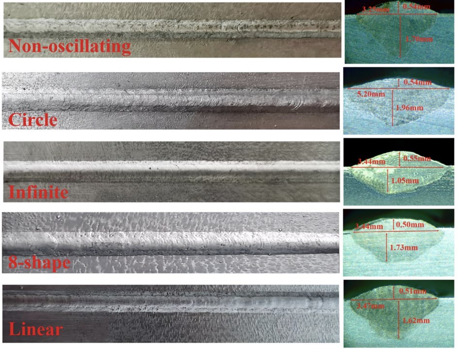
Figure 3. Weld formations of different oscillation patterns [15].
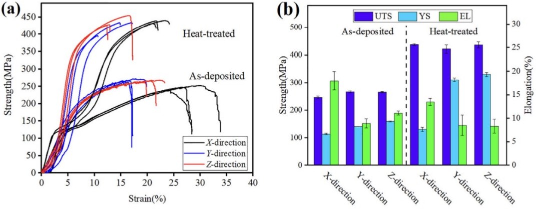
Figure 4. (a): Tensile results of deposited and heat-treated samples (b) Elongation percentage of deposited and heat-treated samples [15].
Other than LAM techniques, casting is also a commonly used aluminum alloy processing technique especially in the automotive industry when producing suspension components. Traditional forging methods consists of 4-5 steps including ending and forging leading to the final product, this means processing costs are high and quality control is difficult [19]. Near net shape casting is a method that can resolve these problems, the concept of this method means that the shape of the ingot was designed similar to the shape of the forged product by direct chill (DC) casting, skipping the extrusion and bending procedures, making the manufacturing of components easier. A study by GUO [19] demonstrates the effects of near net shape casting with casting automobile suspension parts out of 6xxx aluminum alloy. First, simulations and mesh models were created, allowing researchers to optimize the casting parameters before actually casting the part. Then, hot compression tests for the alloy as well as property tests of the suspension parts were also carried out.
Results from the study shows that from trial and error, the researchers were able to create a successful near net shape cast using 6xxx aluminum alloy. Figure 6 shows a casting defect experienced in the study due to the inadequate cooling conditions. To resolve this problem, the researchers changed the cooling conditions by modifying cooling water distribution. Mathematical models and boundaries were also created and verified to be accurate. Figure 5 gives comparisons of the temperature histories between calculated results and measured results, upon which close correlation can be observed between these two results, meaning the mathematical models and boundaries can be used to simulate the process of casting. Table 2 shows mechanical properties of the cast aluminum component at around 386 MPa in terms of yield strength and 410 MPa in terms of tensile strength [19].
In summary, the near net shape casting technique is verified to be a functional and reliable technique able to be implemented in automotive component manufacturing. The study also provides methods to simulate casting results which will help engineers in casting processes. Yield strengths and tensile strengths are both high enough to indicate that the cast aluminum alloy component will be safe and reliable for use.
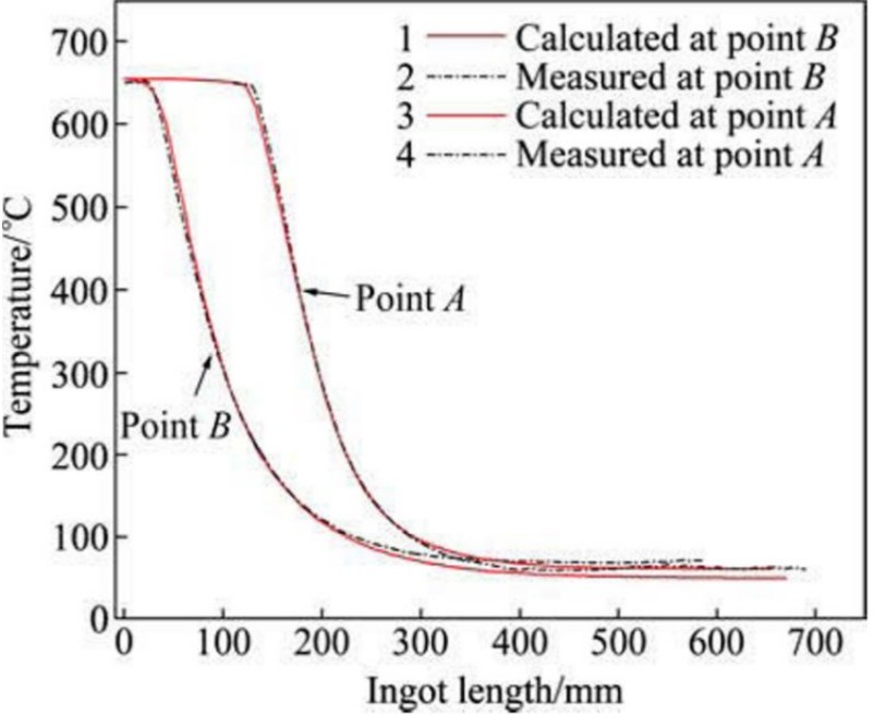
Figure 5. Comparison of temperature to Ingot length between calculated and measured results [19]
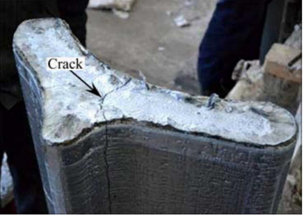
Figure 6. Cracking defects inside cast ingot [19]
Table 2. Mechanical properties of automobile suspension [19]
Position | Yield strength/MPa | Tensile strength/MPa | Elongation/% |
Strengthening rib | 386.5 | 413.0 | 11.8 |
Web plate | 386.0 | 410.5 | 12.5 |
2.1.3. Corrosion Resistance
Aluminum in its pure form is very resistant to corrosion but isn’t great for application in the automobile industry due to its low strength compared to aluminum alloys. However, alloying means decreasing the amount of pure aluminum in the material, causing corrosion resistance to decrease. The relationship between alloy series and corrosion resistance is described in figure 7–it can be seen that the increase in strength causes a decrease in corrosion resistance. [3] Thus, engineers will need to find ways to improve the material so it can have both high strength and corrosion resistance, for which, coatings can be applied to the surface of the material to increase corrosion resistance while strength is virtually unaffected. A research paper written by Yu [4] discusses how anodized aluminum alloys affect corrosion resistance. The aluminum used in the study was A6061, it contains magnesium and silicon as its major alloying contents with magnesium being an element not very resistant to corrosion. The anodic oxidation (a treatment method used to control the thickness of oxide layers formed on the surface of the material) solution used to treat the aluminum alloy consists of 98% sulfuric acid and citric acid. In addition, pretreatment of the aluminum alloy was also conducted by cleaning its surface with acetone, removing excess grease by using a 10% sodium hydroxide solution, and etching the sample with a 50% hydrofluoric acid solution. In addition, post-sealing treatment was carried out on two of the already anodized samples by using boiling water and potassium dichromate. After that, immersion testing was carried out by submerging the anodized aluminum sample in a 3.5% sodium chloride solution to observe corrosion. Finally, a Vickers hardness tester will also be used to conduct hardness tests on the anodized samples at a 0.2kg force for 15s.
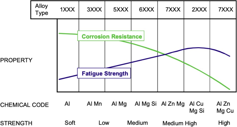
Figure 7. The Effects of Alloying Elements on Corrosion Resistance and Fatigue Strength [3].
Submerging the four aluminum alloy samples in 3.5% sodium chloride has yielded the data in figure 8. It is very clear that sample a, the un-anodized sample has the most weight loss of 80+ mgcm-2 over 9 days anodized samples b, c, and d have lost less weight than 10 mgcm-2 of weight. The corrosion patterns in figure 8 are also not gradual, but rather sudden as the change from day 3 to day 6 is the most extreme. In summary, anodization does effectively increase corrosion resistance. Regarding the hardness test, Figure 9 shows hardness increasing as additional sealing steps are added, the sample with the highest hardness had been post-sealed with potassium dichromate while the sample with the lowest hardness is the sample isn’t modified in any way [4]. Although this study doesn’t directly discuss strength, another study by Cahoon [20] suggests that hardness can be used to “estimate other mechanical properties of metals” as shown in Table e. The method of sealing with potassium dichromate has been cited to be unstable in basic or neutral solutions according to a study by Zuo [21], it states that pitting is probable at higher potentials, possibly damaging the Aluminum alloy.
Table 3. Hardness, Strain Hardening Coefficient, Yield Strength and Ultimate Strength for 65S Aluminum [20]
Specimen | Pct Reduction in Area | Aging Time at 160°C hr | Hardness, Dph | Stress at 8 pct Strain, kg/mm2 | n | m-2 | 0.2 Pct Offset Yield Strength, kg/mm2 | Ultimate Tensile Strength, kg/mm2 |
Al | 0 | 51.2 | 18.0 | 0.35 | 0.28 | 9.5 | 21.5 | |
A2 | 7.6 | 67.0 | 21.9 | 0.12 | 0.13 | 18.0 | 21.5 | |
A3 | 15.0 | 74.8 | 24.7 | 0.08 | 0.09 | 19.3 | 22.4 | |
A4 | 23.3 | 79.8 | 25.0 | 0.06 | 0.06 | 21.5 | 22.4 | |
A5 | 35.0 | 90.0 | 29.0 | 0.05 | 0.04 | 25.0 | 26.6 | |
A6 | 40.0 | 90.8 | 29.4 | 0.07 | 0.05 | 25.9 | 26.3 | |
A7 | 51.8 | 94.9 | 30.5 | 0.06 | 0.04 | 26.9 | 27.5 | |
A8 | 57.0 | 101.0 | 33.1 | 0.04 | 0.07 | 29.2 | 30.0 | |
A9 | 65.8 | 103.0 | 32.5 | 0.05 | 0.07 | 28.8 | 29.5 | |
A10 | 0 | 58.7 | 20.6 | 0.36 | 0.29 | 10.4 | 22.5 | |
All | 8 | 70.1 | 24.0 | 0.28 | 0.25 | 14.8 | 24.4 | |
A12 | 12 | 82.4 | 26.5 | 0.25 | 0.22 | 17.5 | 26.2 | |
A13 | 16 | 78.6 | 27.5 | 0.22 | 0.17 | 17.7 | 26.6 | |
A14 | 18 | 85.6 | 28.0 | 0.17 | 0.12 | 19.7 | 27.1 | |
A15 | 20 | 84.8 | 27.8 | 0.23 | 0.18 | 19.8 | 27.1 | |
A16 | 24 | 91.1 | 31.0 | 0.19 | 0.14 | 24.2 | 29.2 | |
A17 | 30 | 93.8 | 30.4 | 0.16 | 0.13 | 24.5 | 28.6 | |
A18 | 48 | 99.0 | 31.8 | 0.15 | 0.17 | 26.7 | 29.7 |
In conclusion, anodization is an effective coating method that increases the corrosion resistance of A6061 against salt solutions while also increasing its yield strength, creating a material both high in strength and corrosion resistance. This is suitable for application in lightweight automobile components also located on the bottom of cars that are exposed to road salt, minimizing the damage it can do to the various components of the vehicle. The corrosion resistance of A6061 sealed by a potassium dichromate solution exhibits the best corrosion resistance as it loses least mass. This method is used in combination with anodization for the most desirable effects.
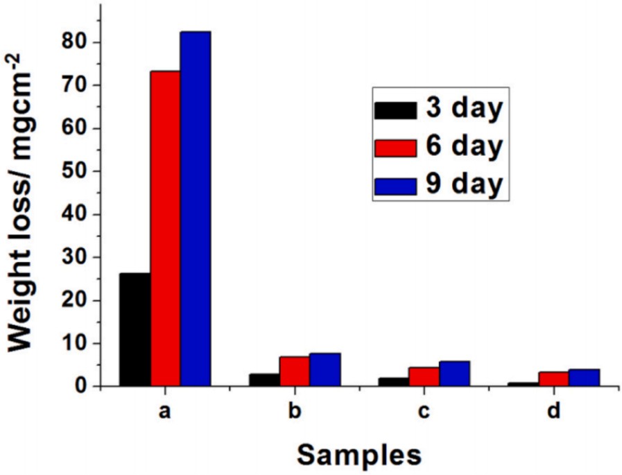
Figure 8. Vickers hardness of anodized and sealed 6061 aluminum alloy; a: 6061 aluminum alloy; b: anodized 6061 aluminum alloy; c: anodized 6061 aluminum alloy after boiling water sealing; d: anodized 6061 aluminum alloy after potassium dichromate sealing [4].
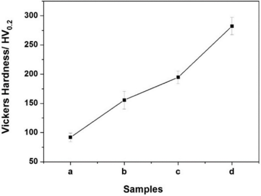
Figure 9. Influence of immersion time on weight loss of different samples after immersion in 3.5 % sodium chloride solution [4].
2.2. Magnesium Alloy
Magnesium alloy is a kind of material composed of magnesium with other elements. Mg alloys, non-ferrous material, are characterized with low density (about 1.74g/cm³), high strength, high modulus of elasticity, good heat dissipation, good vibration damping, high ductility, and acceptable corrosion resistance [22]. The main alloying elements are aluminum, zinc, manganese, cerium, thorium and a small amount of zirconium or cadmium. The most widely used is magnesium aluminum alloy, followed by magnesium manganese alloy and magnesium zinc zirconium alloy. It is mainly used in aviation, aerospace, transportation, chemical industry, and other industrial sectors [23].
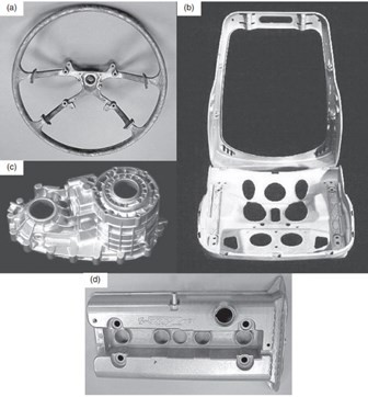
Figure 10. example of some Mg alloy components: (a) magnesium steering wheel core for Toyota Camry weighing 0.75 kg, (b) seat support for Jaguar and Fiat models weighing 2.6 kg, (c) rear transfer case made from AZ91D weighing 2.7 kg, and (d) AZ91 magnesium alloy cam cover for Ford Zetec engine weighing 0.9 kg [23].
2.2.1. Strength
Magnesium alloy is a high strength material that van be used in vehicle industry. However, there is always an inverse relationship between yield strength and other mechanical properties, such as stretch formability [1], weight, elongation, ductility, etc. So in order to solve this problem, Zhang [5] utilized CALPHAD(Calculation of Phase Diagram) to design a crossover alloy, Al-5.63Mg-5.43Zn-0.51Cu, which has ultra-high strength and acceptable elongation, Liu [6] refined grain size and depressed intergranular deformation simultaneously to design Mg-1Sb-1Mn-1Sn-0.2Zn which can achieve preeminent strength-ductility synergy through trace co-addition of Sn and Zn( the schematic of analyses can be seen from Fig.12) , Tian [7] invented an ultra-light Mg alloy with exceptional Young’s modulus and great strength, Peng [24] developed a lightweight and with high mechanical strength alloys system by the low- temperature extrusion at 250 centigrade, Gu [25] designed a series of lightweight Mg alloy with high strength by precipitating a large number of high Young’s modulus phases, Ji [26] designed low-cast Al35Mg30-xZn30Cu5Six(x=5,10,15) lightweight alloys by electric melting, Li [27] developed a lightweight Mg alloy which has high strength and considerable damping capacities.
The results of those experiments are all have positive influence in the application of automobiles, as they not only have a higher strength comparing to the normal Mg alloy, but in some specific mechanical properties these newly designed alloys also have better performances. For example, we can see from the Fig.11 that the yield strength and elongation of Al-5.63Mg-5.43Zn-0.51Cu are 570.7Mpa and 9.5%, respectively [5], which are all higher than the normal Mg alloys. From the Table 4 we can know that the tensile yield strength and compressive yield strength of SMTZ1110 increases from 196Mpa and 193Mpa to 301Mpa and 273Mpa [6]. As a result, by using multiple and different ways to design new Mg alloy we can get a better alloy that with higher yield strength and lightweight or other mechanical properties we can implement in the automobiles as structural components.
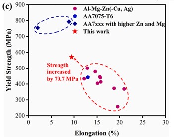
Figure 11. comparison of mechanical properties among the reported Al-Mg-Zn based crossover alloys and 7xxx series high-strength alloys [5].
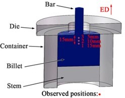
Figure 12. Schematic illustration of the observed positions in the residue for microstructure evolution analyses [6].
Table 4. Mechanical properties of SM11, SMT111, SMZ110, and SMTZ1110 extrusions [6].
Alloys | TYS/Mpa | UTS/Mpa | TEL/% | CYS/Mpa | CYS/TYS |
SM11 | 196±1 | 245±3 | 23.3±1.3 | 193±2 | 0.98 |
SMT111 | 232±2 | 303±4 | 19.8±0.7 | 224±2 | 0.97 |
SMZ110 | 260±2 | 326±5 | 22.7±1.8 | 227±4 | 0.87 |
SMTZ1110 | 301±3 | 361±4 | 23.4±1.6 | 273±3 | 0.91 |
2.2.2. Processing difficulty
There are a lot of problems in processing Mg alloy, such as magnesium has poor plasticity and machinability, and problems such as cracks and deformation are easy to occur; magnesium alloy has strong oxidation, which is easy to produce defects such as oxide skin and porosity during processing, affecting the mechanical properties of the material; magnesium alloy has a low ignition point, which is easy to cause safety accidents such as fire and explosion during processing; magnesium has good thermal conductivity and is likely to be distorted due to high temperatures generated during processing [28]. So in order to solve these problems, many methods have been used. For example, we can use sheet rolling and semi-solid forming (procedures can be seen in Fig.15) to reduce the grain size of cast magnesium alloy, thereby improving its strength and plasticity, and we can also use surface laser treatment technology to improve the surface quality and corrosion resistance of magnesium alloy [29]. In addition, by using solid forming and liquid forming we can refine grain to increase the machinability and plasticity [28]. Peng [30] implemented asymmetric deformation, which is achieved by differential temperature rolling(DTR), to optimize the basal texture of wrought Mg alloy, finally leading to the improvement of ductility and formability.
There are many contemporary forming methods like thermal analysis technique, to help improve the structure and properties of Mg alloy, so we can solve the problems that exist in the processing Mg alloy. And we can also add cutting coolant to help reduce the thermal conducting so that the Mg alloys are less likely to be distorted in high-speed cutting process [31]. From the Fig.13 we can know that the aging process produce the maximum tensile strength and from the Fig.14 we can tell that the water process produce the maximum elongation. So now with so many modern processing methods, we can solve some problems that happen in the processing Mg alloys, and this will boost the development of the vehicle industry as many automobile components can be made in Mg alloys and the mechanical properties of Mg alloys are mostly better than the steel that currently used.
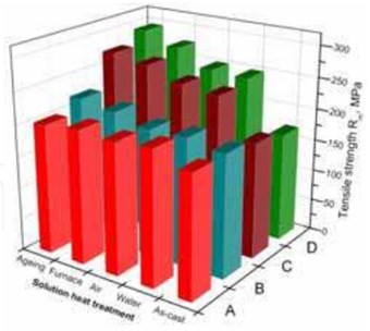
Figure 13. Results of tensile strength Rm measurements of magnesium cast alloys: A – MCMgAl3Zn1, B – MCMgAl6Zn1, C – MCMgAl9Zn1, D – MCMgAl12Zn1 [29]
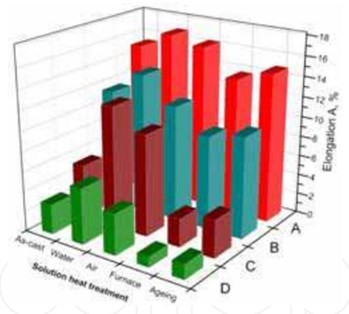
Figure 14. Results of elongation A measurements of magnesium cast alloys: A – CMgAl3Zn1, B – MCMgAl6Zn1, C – MCMgAl9Zn1, D – MCMgAl12Zn1 [29]
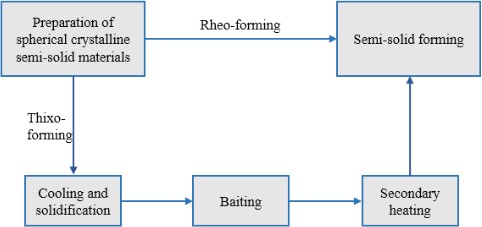
Figure 15. Schematic diagram of semi-solid forming [28].
2.2.3. Corrosion resistance
It is important to find a material that has high corrosion resistance and other suitable mechanical properties as if a material has low corrosion resistance, the structure of this material will be destroyed and some mechanical properties will decrease, thus have bad influence on the lifespan and safety. And with the intention to solve this problem, Kale [32] and his team used anodizing technique to fabricate Ni-Mg-Ag alloy electrodeposited material on the Al surface. They first made 4 types of alloy, ED-NM, ED-NMA, ANO-EM and ANO-NMA, then they compared the ability of corrosion resistance of each alloy. Sun [33] introduced a hierarchal micro-nano β phase framework into a Mg-Al alloy through facile heat treatment, a simple and easily implemented heat treatment method, which can enhance the corrosion resistance of the alloy. The experimental procedures involved producing a binary Mg-13Al alloy cylindrical ingot through smelting casting, machining samples from the interior of the ingot, solutionizing the samples at 415℃ for 48 h, rapidly quenching them in water, and aging them at 200℃ for 24 h. The strength test of magnesium alloy is carried out by tensile test. The following are the procedures: first prepare the tensile sample, then start the tensile test: put the sample into the tensile testing machine, and stretch at a constant tensile speed (0.5mm /min), third record stress-strain curve: the stress and strain of the specimen are measured by the tensile testing machine, and the stress-strain curve is drawn, at last calculate mechanical properties.
By observing the microstructures of those 4 alloys and testing mechanical properties, such as hardness and strength, we can get the resulting data of those alloys just as shown in the Table 5. We can know from the table that ED-NM has the highest corrosion rate of 1.5022mpy and the ANO-NMA has the lowest of 0.6314mpy. And it is evident that the change in nanostructure can improve the strength of the alloy. And in Sun’s experiment, we can learn from the Table 6 and Fig.16 that all the investigated alloys have almost equal corrosion potential, but after immersion for 8 hour, the aged alloy becomes greater than the as-cast and solutionized alloys. Also through the analysis of the microstructure of the Mg-13Al, we can know that we can successfully prepared a hierarchal micro-nano β phase framework which can significantly enhance the corrosion resistance of the Mg-Al alloys in the 0.6 M NaCl solution. These researches will have positive effect in vehicle industry as with high strength and high corrosion resistance materials, the safety and lifespan of vehicles will be improved.
Table 5. The corrosion results and mechanical strength property of Ni–Mg alloy and Ni–Mg–Ag alloy electrodeposits on anodized and without anodized Al surface [32].
Alloy Name | Jcorr(A/Cm2) | Ecorr(mV vs. SCE) | Rp(kΩ cm2) | Corrosion rate(mpy) | corrosion rate(mmpy) | Rs(Ω cm2) | Rct(kΩ cm2) | Hardness(HV) |
ED-NM | 3.53×10^(-6) | -738.3 | 2.311 | 1.5022 | 3.816×10^(-2) | 8.977 | 1.111 | 225 |
AND-NM | 3.14×10^(-6) | -671.5 | 2.529 | 1.3343 | 3.389×10^(-2) | 8.882 | 1.286 | 307 |
ED-NMA | 3.30×10^(-6) | -726.5 | 2.510 | 1.4033 | 3.565×10^(-2) | 9.226 | 2.713 | 440 |
AND-NMA | 1.48×10^(-6) | -470.9 | 6.861 | 0.6314 | 1.604×10^(-2) | 11.65 | 3.322 | 567 |
Table 6. Corrosion parameters extracted from polarization curve [33].
Ecorr(V/SCE) | Ecorr(V/SCE) | Icorr(/mA) | Icorr(/mA) | |
0.5h | 8h | 0.5h | 8h | |
As-cast alloy | -1.42±0.011 | -1.49±0.005 | 0.25±0.038 | 2.48±0.149 |
Solutionized alloy | -1.42±0.010 | -1.50±0.004 | 0.28±0.015 | 3.05±0.398 |
Aged alloy | -1.42±0.020 | -1.43±0.007 | 0.40±0.112 | 1.29±0.133 |
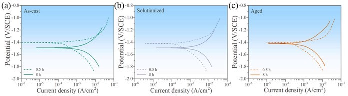
Figure 16. Potentiodynamic polarization curves of (a) the as-cast, (b) solutionized, and (c) aged alloys [33].
2.2.4. Fatigue
In the designation of materials, we should consider the fatigue as it will influence the durability and safety of the materials, so it will be important for us to find or design materials that have high fatigue properties. And other researchers have made many investigations on this problem. For example, Kim [34] compared the high-cycle fatigue resistance between extruded SEN9 alloy and the extruded AZ91 alloy, Marko [35] discovered that under the LCF criterion, it would be more favorable environment for low cycle fatigue of Mg alloy at hand if the temperature increases, Huang [36] investigated in detail by OM, SEM and TEM (the running system can be seen in Fig.19) and found that the Zr- and/or Hf-rich primary particles and precipitates form in the alloys have a significant effect on the fatigue properties, Zhu [37] studied the microstructure, surface morphology features, hysteresis loops and tested the low-cycle fatigue life of AZ31 alloy and GW102k alloy.
From the Fig.17 and Fig.18 we can know that the high-cycle fatigue resistance of SEN9 is lower than the AZ91. In the Fig.20 we can be told that the AZ31 alloy have a shorter low-cycle fatigue life than the GW102k alloy. So we can know that researchers have found many Mg alloys with high fatigue properties, and some people have developed a model to predict the low-cycle fatigue life of Mg alloys [38]. So it would be helpful for us to choose some Mg alloys that have long enough fatigue life and these Mg alloy with high fatigue properties will be beneficial to the automobile industry as it can help improve the safety and durability of vehicles.
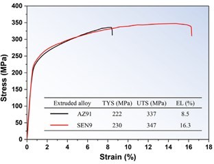
Figure 17. Tensile stress–strain curves and tensile properties of extruded AZ91 and SEN9 alloys. TYS, UTS, and EL denote the tensile yield strength, ultimate tensile strength, and tensile elongation, respectively [34].
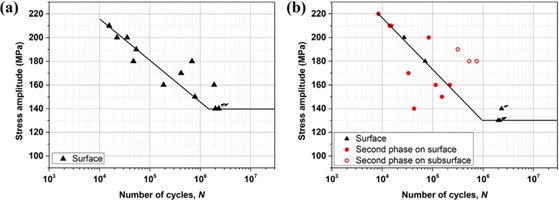
Figure 18. Results of high-cycle fatigue tests (S–N curves) of extruded (a) AZ91 and (b) SEN9 alloys. The fatigue crack initiation sites are specified in parentheses [34].
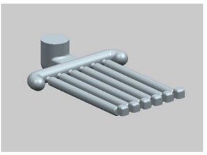
Figure 19. Schematic sketch of the running system used in Huang’s research [36].
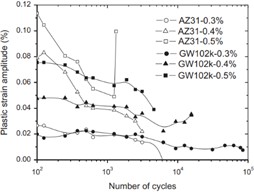
Figure 20. Evolution of plastic strain amplitude for GW102k and AZ31 alloys [37].
2.3. Glass Fiber Polymer Composites
Glass fibers are commonly used to reinforce polymers due to their excellent mechanical properties, versatility and low cost [39]. They make up 90% of fibers used in polymer composites [40]. The main types of glass fibers are E-glass, high-strength (HS)-glass, and corrosion resistant (CR)-glass. Glass fiber reinforced polymer composites are generally produced by pressing raw material into tight holes followed by their solidification, and they can be homemade through a simple method shown in Fig. 21. Since the 1980s they have been used for various applications in different industries, including automotive parts, concrete and blast protection. There is growing interest in using these composites to replace metal parts in vehicles due to their low weight, low cost, and design flexibility.
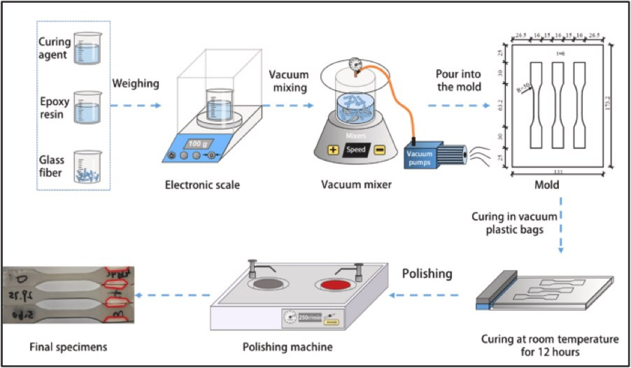
Figure 21. The preparation flow chart of a simple method of making glass fiber reinforced composites [41].
2.3.1. Yield Strength
Glass fiber reinforced polymers are attractive for usage in car bodies due to their high strength-to-weight ratio. Yield strength is important in car body materials to resist denting and ensure the safety of passengers. Therefore it would be useful to increase the yield strength of polymer composites [42], [43]. It was observed that the properties of nylon composites were greatly changed by an increase in fiber but not a change in fiber length. The research paper [44] aimed to investigate the yield strength of nylon composites based on the glass fiber loading, to potentially increase the yield strength through greater amounts of glass fiber used. The researchers prepared samples of nylon composites containing 0%, 3%, 6%, 9% and 12% glass fiber composition by vacuum assisted resin transfer molding. They carried out tensile tests using a universal testing machine to find the yield strength.
The blend with the highest glass fiber composition of 12% began permanent deformation at 19.66 MPa, which is 43% higher than that of the pure blend with no glass fiber. Yield strength increases greatly and linearly with percentage of glass fiber, as seen in Fig. 22. Glass fiber composition can be increased to 60% to raise yield strength to 160 MPa [45]. The density of this composite would be 2.0 g/cm3 [10], which is lower than 2.7 g/cm3, the density of AA6016A aluminium alloy, and 7.8 g/cm3, the density of steel. The yield strength of AA6016A varies from 110-210 MPa, while the yield strength of steel used in automotive frames is 185 MPa. In conclusion, the amount of glass fiber in the polymer can be raised to increase the yield strength of the composite, while keeping density below the density of aluminium. This could make glass fiber reinforced polymer composites a suitable material to replace aluminium in the car body, based only on yield strength and density.
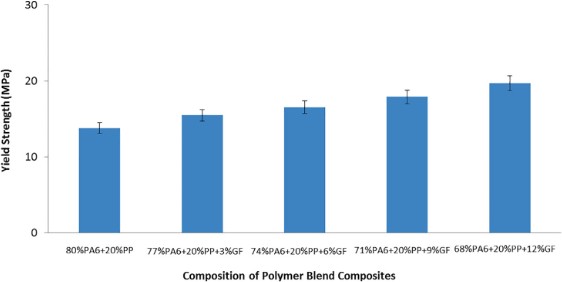
Figure 22. Graph of yield strength against composition of polymer blend composites [44]
2.3.2. Fatigue Performance
High fatigue performance is important for materials used in car bodies to maintain passenger safety and structural integrity. The fatigue performance of glass fiber polymer composites should be improved for usage in car bodies. One method of achieving this aim is to use graphene nanoplatelets (GNP) as a coating. Previous research has shown that usage of GNP effectively improves the wear resistance of basalt-epoxy composites [46] and carbon fiber composites [47]. A.K. Singh and R. Bedi conducted an experiment aiming to improve the fatigue life of glass fiber reinforced composites by further reinforcing them with GNP [48]. Two samples of glass fiber laminate composites were created, and one was spray coated in a layer of GNP, PVP and ethanol. Fatigue tests were then carried out using the MTS 250 kN servo-hydraulic system.
The fatigue data for the two samples was modelled using an S-N curve. A lower slope was obtained for the reinforced sample, which indicates better fatigue performance. Run out was observed after 10^6 cycles at 114.26 MPa for the control sample and
150.61 MPa for the sample reinforced with GNP. The GNP coating increases bonding between the fiber and the polymer matrix, while deflecting crack paths [47], which results in the laminate being able to withstand more cycles. The reinforced sample also exhibited less stiffness degradation after fatigue loading, as it was able to withstand up to 10 times the number of cycles before losing 10% stiffness. This shows that GNP reinforcement could greatly improve the fatigue performance of glass fiber reinforced polymer composites by delaying cracks and reducing stiffness degradation. Therefore the coating will enhance the composite’s durability and ability to bear varying loads, making it a more suitable material for use in a car body.
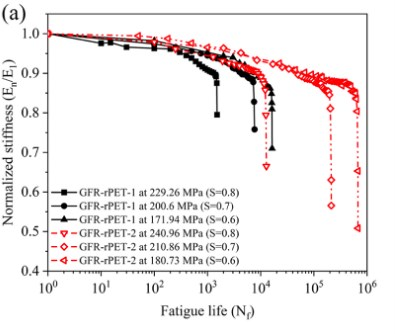
Figure 23. Stiffness degradation vs. fatigue life, where GFR-rPET-1 is the control sample and GFR-rPET-2 is reinforced with GNP [48].
2.3.3. Ease of Processing
Glass fiber reinforced polymer composites are usually manufactured ready to shape, but further manufacturing is needed for complex features such as holes and pockets. Fiber composites are prone to damage during drilling such as delamination and fiber pull-out [49]. Micro-holes (diameter <1mm) are useful for certain automotive components. Researchers have previously created specialized tools for micro-drilling composites [50], but these are costly and increase machining time. It is also difficult to detect damage in these composites due to drilling, and undetected damage may cause faster degradation or compromise the structure of the automotive. Wang et al. [51] tested a system that employs a neural network to analyse terahertz time-domain spectroscopy (THz-TDS) signals reflected by laminates. This would help to predict defects of various depths in composites. For testing the system, 17725 data points were taken from both defective and non-defective areas in a GFRP laminate. 80% were used to train the neural network and 20% to validate its accuracy.
After being tested on the validation data points, the macro F1 score, which is an average harmonic mean of precision overall output categories, was taken. The models all had high F1 scores of 0.8 and above. The results showed that the 1D-CNN model was the most accurate out of all models taken, which F1 scores of 0.91 and 0.92. This makes the analytical model highly accurate in detecting defect depth in GFRP laminates. It is an appropriate, non-destructive solution for the complex calculation of defect depth and can be used to separate defective and non-defective composite laminates, thus enabling manufacturers to detect delamination in micro-drilled composite parts. In conclusion, the neural network is a viable and accurate system to predict depth of defects in glass fiber composite laminates. This could be useful in separation of defective and non-defective laminates and allow manufacturers to add complex features such as micro-holes to glass fiber composites.
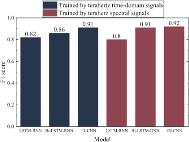
Figure 24. Graph of F1 score against analytical model for different methods of neural network training [51]
2.4. Carbon Fiber Polymer Composites (long/short)
Carbon fibre is a type of material that is made by welding thousands of stripes of carbon which mainly have a 5-10 micrometre diameter. [52] Carbon fibre usually has a character of high strength and is lightweight. [53] Thus, it is usually used in aerospace production, military, race car and some specific race sport [54]. There are many kinds of carbon fibre, which are differentiated by the welding technology or the length of the carbon stripes that are used, thus also having a different level of performance. However, due to the complicated production process, carbon fibre is extremely expensive.
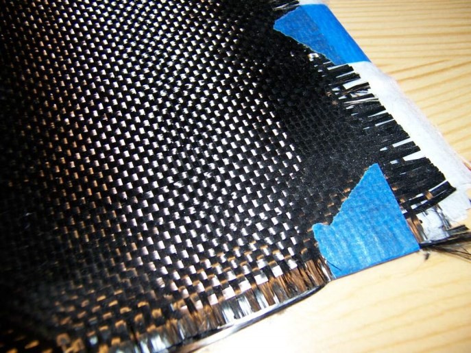
Figure 25. a sample of carbon fibre [55]
2.4.1. Strength
Carbon fibre has a high strength, and high yield strength is also included, when mixing with other materials, it is also able to reinforce and improve its mechanical abilities [56]. To measure the strength of carbon fibre, the sample is pulled through a test in which the samples are compressed until it breaks using an extensometer. To consider the different orientations, the samples were cut at different angles [57]. All of them were cut into the same shape having the same thickness, shown in figure2 in which the extensometer which is used to test its critical value of deformation, is placed at the middle of the sample. The sample will be compressed until it undergoes plastic deformation or breaks.
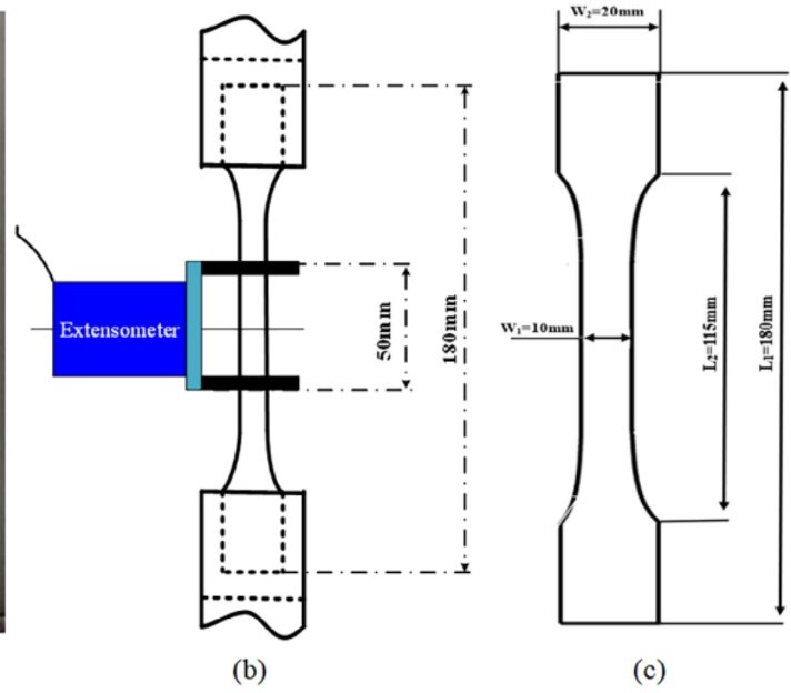
Figure 26. position of the extensometer, and the looking of the sample [57]
The results have shown that, taking the hood as an example, using the right parameters the stiffness has increased by 9% compared to an original steel hood. Though there is a small fall in bending stiffness, it is still in safe ranges. Carbon fibre made materials can replace parts that need high pressure. And in some cases, it can increase its strength while reducing the weight at the same time.
2.4.2. Corrosion
Carbon fibre has a good chemical stability, it rarely reacts with any kind of acid or base, compared to PVC, which is an alternative and has terrible chemical stability, even emitting toxic gas during the reaction [58]. Carbon fibre is often mixed with other alloys that are relatively reactive in order to make the compound less feasible. To prove its resistivity to corrosion, Mg alloy is melted and compressed into CF, forming a CF/Mg composite [59]. The open circuit potential (OCP), Electrochemical Impedance Spectroscopy (EIS) curves, and potentiodynamic polarization curves which helps us to investigate the corrosion behaviour under different environments, were measured byCS310 electrochemical workstation, in which the potentiodynamic polarization curves were fitted.
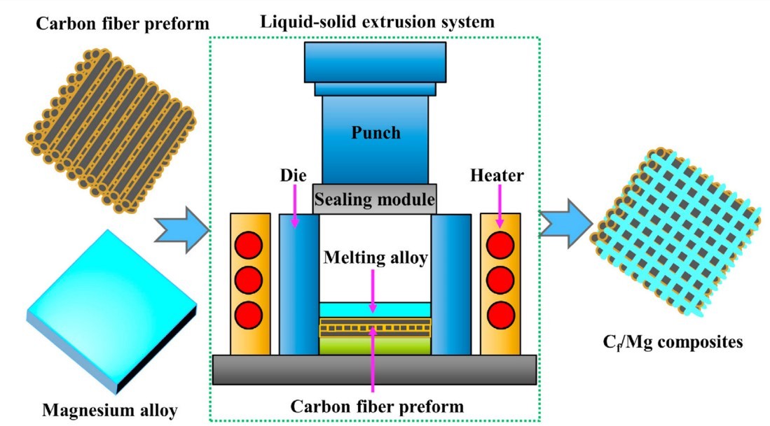
Figure 27. simple graph demonstrating how the material is made [59]
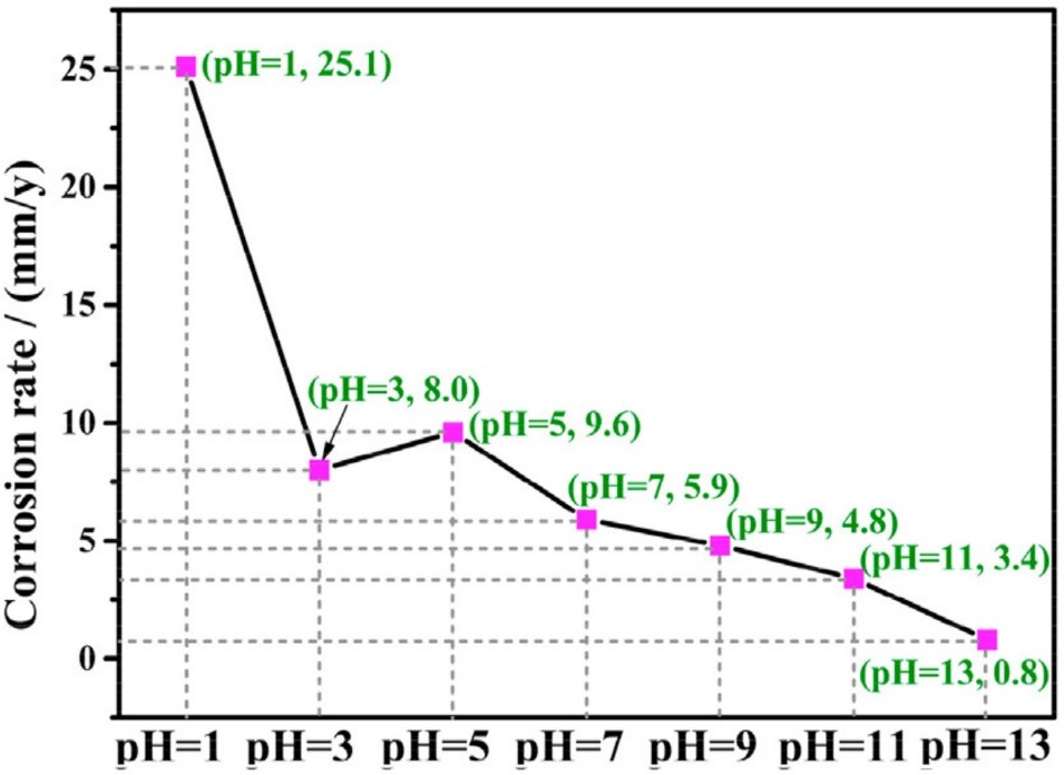
Figure 28. change in corrosion rate followed by the change in pH value [59]
The results have shown that the material shows a decrease in the corrosion rate as the pH rises. The sample, which is a Mg alloy had a current of 1.1×10^-3 A/cm^2 in the neutral solution, while the new material had only 2.6×10^-4 A/cm2 meaning that less is being corroded. Thus, the improvement of the resistivity to corrosion has shown that carbon fibre has an outstanding tolerance on the change in pH values [59]. CF is often used as an alternative for exterior components of a car; thus, it is mostly exposed to neutral, weak acidic or alkaline conditions. According to the graph, around the pH value of 7, the corrosion rate is relatively small, so it can be used for a longer time. However, usually when coming to the direct exposure of it, it is usually protected with a layer of coating.
2.5. Carbon Fiber Polymer Composites (weave)
Carbon fibers contain at least 92% carbon and possess excellent tensile strength, low density, high thermal stability, good thermal conductivity, and resistance to creep. They are widely used in composite materials and can be incorporated into composite components through various manufacturing methods. The atomic structure of carbon fiber is similar to graphite, consisting of layers of carbon atoms (graphene sheets) arranged in a regular hexagonal pattern, as shown in Figure 29 [60] The development of carbon fiber can be divided into four stages: early development, growth of the carbon fiber composite industry, major applications of carbon fiber composites, and expanded applications of carbon fiber composites. The early development stage occurred mainly in the 1950s and 1960s, while significant breakthroughs in the application of carbon fiber composites were achieved in the 1990s and 2000s [61].
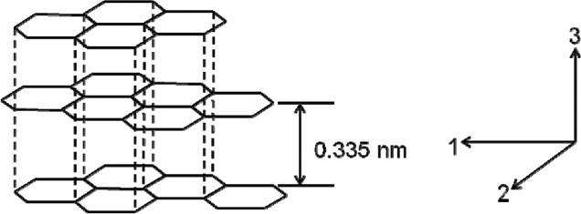
Figure 29. Structure of graphitic crystals and crystal directions [60]
2.5.1. Strength
Researchers introduce a new additive manufacturing technique that allows for the integration of features in woven structures that were previously only achievable through destructive processing methods. They conducted a study on the printing of multi-layered composite materials using carbon fiber Tow coated with nylon. In order to evaluate the performance of these printed composite materials, a load response study was carried out. By routing 6mm holes into the multi-layered woven composite structure, the mechanical properties of the resulting components were tested and compared to specimens drilled after printing. The specimens were composed of 9 layers of woven fabric, forming a standardized test sample with a thickness of 3.1mm, which was used for single shear and double shear testing (ASTM D5961).
The results of the study show that the new “Tailor Woven” specimens achieved single shear bearing strengths of up to 214 MPa and double shear bearing strengths of up to 276 MPa, which represent an increase of 29% and 63% respectively compared with equivalent composites in which the hole had been drilled. This enhancement in bearing strength was achieved through the use of a novel additive manufacturing technique for the fabrication of woven multilaminate composites, which allows for the integration of features such as notches previously only possible through destructive machining processes. The specimens were comprised of 9 woven laminates stacked to form a 3.1 mm thick standardized test coupon for single and double shear testing (ASTM D5961). In the discussion section, the authors provide an explanation and analysis of the experimental results. They point out that the “Tailor Woven” specimens achieved a 63% higher bearing strength in double shear testing compared to the drilled specimens and exhibited a significant reduction in notch deformation. However, the “Tailor Woven” specimens showed a sharper “bending” region at strains of 0.02-0.03, which may be attributed to slightly larger clearances in the bolt holes. The authors state that future work will focus on improving the consistency of hole diameter throughout the entire laminate thickness [62]
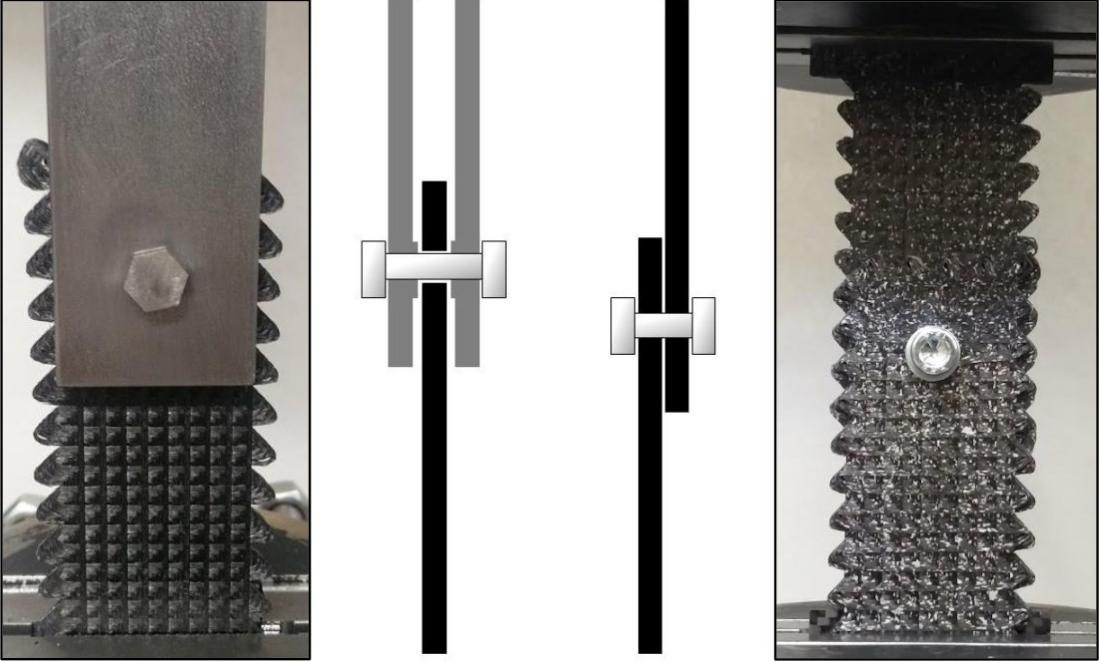
Figure 30. Procedure A: Double Shear (left) and Procedure B: Single Shear (right) setups prior to testing [3]
2.5.2. Processing difficulty
To investigate the effect of tool geometry and cutting parameters on drilling woven carbon fiber reinforced polymer (CFRP) and to optimize the delamination’s apparition in drilling holes. Researchers aims to find the optimal combination of drilling parameters by comparing different modeling methods and using genetic algorithms for optimization to improve the efficiency and quality of drilling CFRP. They utilized response surface methodology and genetic algorithms to analyze and optimize the machining parameters for drilling CFRP. The response surface methodology was employed to establish a relationship model between the input and output variables, while the genetic algorithm was used to search for the optimal solution. In the validation experiments, a 3-3 full factorial design was adopted, and 27 experiments were conducted to investigate the effects of different machining parameters.
The research results indicate that feed rate and drill diameter have the most significant impact on the delamination factor, while the spindle speed has a relatively smaller effect. By optimizing the drilling parameters using genetic algorithms, the delamination factor was reduced by 50% compared to the initial parameters. Both the response surface methodology and artificial neural network models demonstrated good performance in predicting the delamination factor and optimizing the drilling parameters. This study provides in-depth insights into the fine process of drilling woven CFRP and offers a practical approach to determining the optimal drilling parameters. Analytical and numerical modelling is used in future research to optimize tool geometry and develop artificial intelligence programs to help the aerospace industry determine optimal drilling conditions. It is concluded that the use of an auger is the best option to obtain both good drilling quality and productivity [63]. This section discusses the study of drilled composites with emphasis on ten tests performed for different cutting conditions and output averages are considered in this work. These results were used to predict the thrust, moment and delamination phenomena obtained in different geometries by means of Root Mean Square Error (RMS) and Artificial Neural Network (ANN).
2.5.3. Fatigue performance
Carbon fiber reinforced plastics have a broad range of industrial applications. Studying the durability and reliability of carbon fiber reinforced plastics, particularly their fatigue performance, is vital. Although advanced technologies are available for researching the fatigue behavior of CFRP, exploring cost-effective methods is still crucial. Researchers aim to approximate the degradation trends of composite material properties and identify the causes of performance degradation during fatigue processes using molecular dynamics simulations to evade the high perils of long-term fatigue performance experiments. The article incorporates the Molecular Dynamics (MD) method to investigate the fatigue process and performance of carbon-fiber-reinforced epoxy resin. The Molecular Dynamics (MD) method is based on the principles of both Newtonian mechanics and quantum mechanics. It simulates both macroscopic properties and microscopic behavior of materials by numerically integrating equations of motion. The input parameters for molecular dynamics simulations include strain rate, pressure, temperature, density, initial system configuration, and potential energy function. Through the MD method, it is possible to approximate the trend of composite material performance degradation and identify probable reasons for performance degradation during the fatigue process. During the simulation, a fatigue test is conducted by applying a strain-controlled load to the system. The stiffness of the composite material is quantified using the average stress. Moreover, a trigonometric function is used to estimate the stress for every cycle by fitting it to the stress-response curve of the first two cycles.
Firstly, the stress-strain curve of carbon fiber reinforced epoxy resin during the fatigue process is obtained through MD simulation, and the changes in its stiffness and strength were analyzed, as shown in Figure 31. Secondly, through the analysis of the simulation results, the reasons for the degradation of fatigue performance in carbon fiber reinforced epoxy resin are determined, including fiber fracture, interface shear, and resin softening. Therefore, the results of MD simulation can reflect the trend of fatigue performance changes in carbon fiber reinforced epoxy resin and provide reference for further material design improvements. This article mainly discusses the application of MD simulation in studying the fatigue performance of carbon fiber reinforced epoxy resin, as well as the limitations of this method. Specifically, the advantages of MD simulation in studying the fatigue performance of composite materials are discussed, such as providing more detailed information and avoiding human errors in experiments. At the same time, the limitations of this method are also discussed, such as the need for many computational resources and the need to parameterize the model [64]. In the context of automotive engineering, the implications of employing MD simulation for designing carbon fiber-reinforced components are noteworthy. The insights gained from MD simulations can guide the development of automotive parts that exhibit improved fatigue resistance. By fine-tuning the composite composition and structure based on the simulation results, manufacturers can tailor components to withstand the demanding conditions experienced by automobile parts. Furthermore, as automotive components require stringent safety and performance standards, the utilization of MD simulations can aid in optimizing the material properties for enhanced durability.
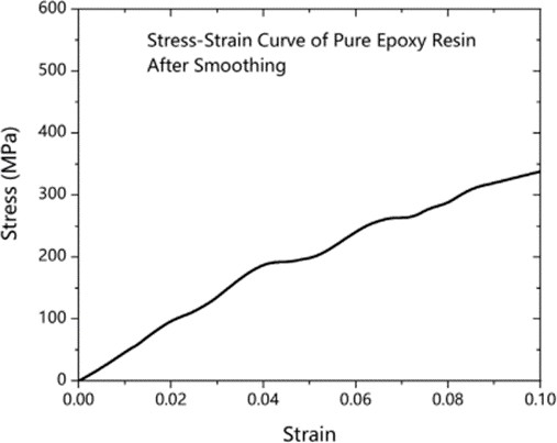
Figure 31. stress-strain curve of epoxy resin after smoothing [64]
2.6. Discussion Summary
In summary, the materials reviewed in this paper each have different mechanical properties, however, in lightweight automobile component manufacturing, all these properties must be considered and balanced. As shown in Fig. 31, carbon fiber and glass fiber polymer composites have similar strength to high-strength steels, but significantly lower density. Magnesium alloy and aluminum alloy have lower strength and higher density than the composites, but still have similar strength and lower density as compared to steel. Fig. 32 shows all fiber composites are excellent in resisting saltwater corrosion; however, aluminum alloys and magnesium alloys are not as good as resisting saltwater corrosion. But it is still far better than compared to steel, which is “bad” at resisting saltwater corrosion. This means fiber composites and metal alloys are good substitutes for conventional steel in automobile components. As shown in Fig. 33, aluminum and magnesium have similar costs to stainless steel but slightly lower strength, and magnesium costs more than aluminum. Glass fiber reinforced polymers have a similar cost and strength to steel, while carbon fiber reinforced polymers are stronger but much more expensive.
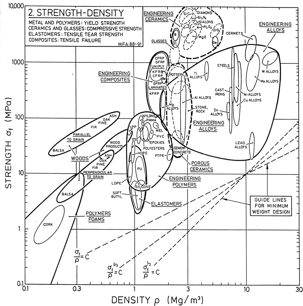
Figure 32. Strength to density ratio of various materials [65].
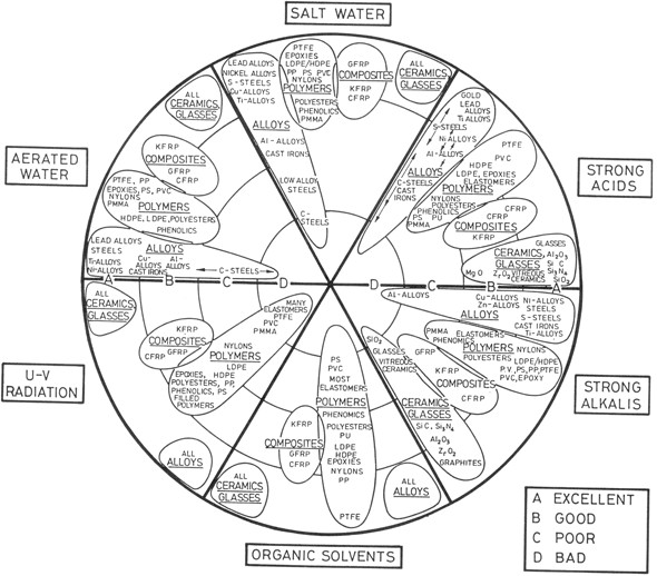
Figure 33. Chart of corrosion resistance of various materials in different conditions [65].
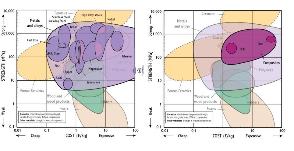
Figure 34. Strength to cost comparison of various materials [66].
3. Conclusion
In this paper, the feasibility of the application of different materials in various parts of the automobile was analysed. The optimal choice will be made by considering the unique properties of every material and the working condition of the discussed component. This research aims to reduce the car’s weight and improve the other mechanical properties as well or at least not maintain its mechanical properties, to reduce the thrust-weight ratio which is the most significant factor influencing vehicle fuel consumption.
In terms of alloy, A6061 reduces the weight of wheel hubs by an impressive 58 per cent without compromising safety - its safety factor is 2.09. Anodizing enhances A6061’s enhanced corrosion resistance to salt solutions and increased yield strength. This makes it ideal for lightweight components located under the vehicle and exposed to road salt. At the same time, the yield strength and elongation of Al-5.64Mg-5.43Zn-0.51Cu are 570.7 ± 2.7 MPa and 9.5 ± 0.2% respectively, making it an ideal alternative to conventional steel. Advances in technology, such as laser surface treatment, contribute to the surface quality and corrosion resistance of magnesium alloys, ensuring their durability and longevity.
For non-metal composites, yield & tensile strength is proportional to the percentage of glass fibre in the polymer. As materials with the same strength, glass fibre is 26 percent lighter than aluminium alloy. The use of additive manufacturing (AM) can enhance the load- bearing strength of woven carbon fiber thermoplastic composites. The printed structure achieved a maximum load-bearing strength of 214 MPa in a single shear test. The highest load-bearing strength of 276 MPa was achieved in a double shear test. When drilling CFRP, the evolution of peel-off and thrust torque at the entrance is particularly dependent on the feed rate value, while the peel-off at the exit is determined by both the feed rate and spindle speed. When the long carbon fibre has a volume in the interval of 0.2-0.4 the stress-strain graph has a great overlap. When the pH value of the surrounding increases, the corrosion rate will greatly decrease, meaning that it is more durable under alkaline conditions.
Next steps for researchers in lightweight automobile components should be focused on the strength, properties, and safety of nanocomposites as well as reducing the cost, processing difficulty, and improving mechanical qualities of current materials discussed in the paper. For example, graphene/A6061 nanocomposites provide unique properties like high melting points, high corrosion resistance, and high durability making the material more suitable for automobile applications.
Acknowledgement
Dongsheng Wu, Kenny Wei, Arin Mo, Vincent Yan and Ruoxi Wang contributed equally to this work and should be considered co-first authors.
References
[1]. W. Zhang and J. Xu, “Advanced lightweight materials for Automobiles: A review,” Mater. Des., vol. 221, p. 110994, Sep. 2022, doi: 10.1016/j.matdes.2022.110994.
[2]. J. Zhou, F. Wang, and X. Wan, “Optimal Design and Experimental Investigations of Aluminium Sheet for Lightweight of Car Hood,” Mater. Today Proc., vol. 2, no. 10, Part A, pp. 5029–5036, Jan. 2015, doi: 10.1016/j.matpr.2015.10.093.
[3]. J. Wang et al., “A crack-free and high-strength Al-Cu-Mg-Mn-Zr alloy fabricated by laser powder bed fusion,” Mater. Sci. Eng. A, vol. 854, p. 143731, Sep. 2022, doi: 10.1016/j.msea.2022.143731.
[4]. X. Yu, G. Zhang, Z. Zhang, and Y. Wang, “Research on corrosion resistance of anodized and sealed 6061 aluminum alloy in 3.5 % sodium chloride solution,” Int. J. Electrochem. Sci., vol. 18, no. 5, p. 100092, May 2023, doi: 10.1016/j.ijoes.2023.100092.
[5]. Z. Zhang, Y. Li, Y. Liu, H. Li, D. Zhang, and J. Zhang, “A novel Al-Mg-Zn(-Cu) crossover alloy with ultra-high strength,” Mater. Lett., vol. 347, p. 134640, Sep. 2023, doi: 10.1016/j.matlet.2023.134640.
[6]. L. Liu et al., “Achieving preeminent strength-ductility synergy of Mg–1Sb–1Mn alloy via trace co-addition of Sn and Zn,” Mater. Sci. Eng. A, vol. 862, p. 144431, Jan. 2023, doi: 10.1016/j.msea.2022.144431.
[7]. G. Tian, J. Wang, S. Wang, C. Xue, X. Yang, and H. Su, “An ultra-light Mg-Li alloy with exceptional elastic modulus, high strength, and corrosion-resistance,” Mater. Today Commun., vol. 35, p. 105623, Jun. 2023, doi: 10.1016/j.mtcomm.2023.105623.
[8]. M. S. H. Al-Furjan, L. Shan, X. Shen, M. S. Zarei, M. H. Hajmohammad, and R. Kolahchi, “A review on fabrication techniques and tensile properties of glass, carbon, and Kevlar fiber reinforced rolymer composites,” J. Mater. Res. Technol., vol. 19, pp. 2930–2959, Jul. 2022, doi: 10.1016/j.jmrt.2022.06.008.
[9]. J. Wong, A. Altassan, and D. W. Rosen, “Additive manufacturing of fiber-reinforced polymer composites: A technical review and status of design methodologies,” Compos. Part B Eng., vol. 255, p. 110603, Apr. 2023, doi: 10.1016/j.compositesb.2023.110603.
[10]. G. Xian, R. Guo, and C. Li, “Combined effects of sustained bending loading, water immersion and fiber hybrid mode on the mechanical properties of carbon/glass fiber reinforced polymer composite,” Compos. Struct., vol. 281, p. 115060, Feb. 2022, doi: 10.1016/j.compstruct.2021.115060.
[11]. R. Nunes, Properties and Selection: Nonferrous Alloys and Special-Purpose Materials. ASM International, 1990. Accessed: Aug. 10, 2023. [Online]. Available: https://dl.asminternational.org/handbooks/edited-volume/14/Properties-and-Selection-Nonferrous-Alloys-and
[12]. K. Loganathan and S. K. Vijaya Siva Subramani, “Design and optimization of aluminium alloy wheel rim in automobile industry,” Mater. Today Proc., Feb. 2023, doi: 10.1016/j.matpr.2023.01.207.
[13]. P. P. Awate, S. B. Barve, P. Pesode, and S. S. Shinde, “Graphene/Al6061 nanocomposite for aerospace and automobile application,” Mater. Today Proc., Jul. 2023, doi: 10.1016/j.matpr.2023.07.075.
[14]. Q. Han, M. Li, Z. Wang, X. Yun, and Y. Ouyang, “Local buckling behaviour and design of aluminium alloy plates in fire,” Thin-Walled Struct., vol. 189, p. 110886, Aug. 2023, doi: 10.1016/j.tws.2023.110886.
[15]. X. Cui, E. Qi, Z. Sun, C. Jia, Y. Zeng, and S. Wu, “Wire Oscillating Laser Additive Manufacturing of 2319 Aluminum Alloy: Optimization of Process Parameters, Microstructure, and Mechanical Properties,” Chin. J. Mech. Eng. Addit. Manuf. Front., vol. 1, no. 3, p. 100035, Sep. 2022, doi: 10.1016/j.cjmeam.2022.100035.
[16]. G. Atxaga, A. Arroyo, and B. Canflanca, “Hot stamping of aerospace aluminium alloys: Automotive technologies for the aeronautics industry,” J. Manuf. Process., vol. 81, pp. 817–827, Sep. 2022, doi: 10.1016/j.jmapro.2022.07.032.
[17]. H. Kumar, R. Prasad, and P. Kumar, “Friction stir processing of hypereutectic Al-Si alloy,” Mater. Today Proc., Jun. 2023, doi: 10.1016/j.matpr.2023.06.105.
[18]. H. Yang et al., “Defects control of aluminum alloys and their composites fabricated via laser powder bed fusion: A review,” J. Mater. Process. Technol., vol. 319, p. 118064, Oct. 2023, doi: 10.1016/j.jmatprotec.2023.118064.
[19]. S. Guo, Y. Xu, Y. Han, J. Liu, G. Xue, and H. Nagaumi, “Near net shape casting process for producing high strength 6xxx aluminum alloy automobile suspension parts,” Trans. Nonferrous Met. Soc. China, vol. 24, no. 7, pp. 2393–2400, Jul. 2014, doi: 10.1016/S1003-6326(14)63362-8.
[20]. J. R. Cahoon, W. H. Broughton, and A. R. Kutzak, “The determination of yield strength from hardness measurements,” Metall. Trans., vol. 2, no. 7, pp. 1979–1983, Jul. 1971, doi: 10.1007/BF02913433. Y. Zuo, P.-H. Zhao, and J.-M. Zhao, “The influences of sealing methods on corrosion behavior of anodized aluminum alloys in NaCl solutions,” Surf. Coat. Technol., vol. 166, no. 2, pp. 237–242, Mar. 2003, doi: 10.1016/S0257-8972(02)00779-X.
[21]. Nouha Loukil, “Alloying Elements of Magnesium Alloys: A Literature Review,” in Magnesium Alloys Structure and Properties, Tomasz Tański and Paweł Jarka, Eds., Rijeka: IntechOpen, 2021, p. Ch. 9. doi: 10.5772/intechopen.96232.
[22]. “Introduction to Magnesium,” in Magnesium, Magnesium Alloys, and Magnesium Composites, John Wiley & Sons, Ltd, 2011, pp. 1–12. doi: 10.1002/9780470905098.ch1.
[23]. P. Peng et al., “Bimodal grained Mg–0.5Gd–xMn alloys with high strength and low-cost fabricated by low-temperature extrusion,” J. Alloys Compd., vol. 935, p. 168008, Feb. 2023, doi: 10.1016/j.jallcom.2022.168008.
[24]. Z. Gu et al., “Designing lightweight multicomponent magnesium alloys with exceptional strength and high stiffness,” Mater. Sci. Eng. A, vol. 855, p. 143901, Oct. 2022, doi: 10.1016/j.msea.2022.143901.
[25]. C. Ji, A. Ma, and J. Jiang, “Mechanical properties and corrosion behavior of novel Al-Mg-Zn- Cu-Si lightweight high entropy alloys,” J. Alloys Compd., vol. 900, p. 163508, Apr. 2022, doi: 10.1016/j.jallcom.2021.163508.
[26]. R. Li, G. Wilde, and Y. Zhang, “Synergizing mechanical properties and damping capacities in a lightweight Al-Zn-Li-Mg-Cu alloy,” J. Alloys Compd., vol. 886, p. 161285, Dec. 2021, doi: 10.1016/j.jallcom.2021.161285.
[27]. Y. Li et al., “Recent advances of high strength Mg-RE alloys: Alloy development, forming and application,” J. Mater. Res. Technol., Aug. 2023, doi: 10.1016/j.jmrt.2023.08.055.
[28]. Leszek A. Dobrzański, Tomasz Tański, Szymon Malara, Mariusz Król, and Justyna Domagała- dubiel, “Contemporary Forming Methods of the Structure and Properties of Cast Magnesium Alloys,” in Magnesium Alloys, Frank Czerwinski, Ed., Rijeka: IntechOpen, 2011, p. Ch. 15. doi: 10.5772/13717.
[29]. P. Peng et al., “Significantly improvement in formability and ductility of AZ31 Mg alloy by differential temperature rolling,” J. Mater. Res. Technol., vol. 26, pp. 1293–1305, Sep. 2023, doi: 10.1016/j.jmrt.2023.07.210.
[30]. P. K. Rout, P. C. Jena, G. N. Arka, and B. Surekha, “Review on Magnesium Alloy Processing,” in Innovative Product Design and Intelligent Manufacturing Systems, BBVL. Deepak, D. Parhi, and P. C. Jena, Eds., in Lecture Notes in Mechanical Engineering. Singapore: Springer, 2020, pp. 421–428. doi: 10.1007/978- 981-15-2696-1_41.
[31]. V. N. Kale, J. Rajesh, T. Maiyalagan, C. W. Lee, and RM. Gnanamuthu, “Fabrication of Ni– Mg–Ag alloy electrodeposited material on the aluminium surface using anodizing technique and their enhanced corrosion resistance for engineering application,” Mater. Chem. Phys., vol. 282, p. 125900, Apr. 2022, doi: 10.1016/j.matchemphys.2022.125900.
[32]. J. Sun et al., “Improved barrier effect of hierarchical micro-nano precipitate framework in magnesium-aluminum alloy for corrosion mitigation,” Corros. Sci., vol. 219, p. 111220, Jul. 2023, doi: 10.1016/j.corsci.2023.111220.
[33]. Y. J. Kim, Y. M. Kim, S.-G. Hong, D. W. Kim, C. S. Lee, and S. H. Park, “Comparative study of tensile and high-cycle fatigue properties of extruded AZ91 and AZ91–0.3Ca–0.2Y alloys,” J. Mater. Sci. Technol., vol. 93, pp. 41–52, Dec. 2021, doi: 10.1016/j.jmst.2021.03.039.
[34]. M. Čanađija, X. Guo, D. Lanc, W. Yang, and J. Brnić, “Low cycle fatigue and mechanical properties of magnesium alloy Mg–6Zn–1Y–0.6Ce–0.6Zr at different temperatures,” Mater. Des., vol. 59, pp. 287–295, Jul. 2014, doi: 10.1016/j.matdes.2014.03.001.
[35]. H. Huang, Y. Dong, Y. Xing, Z. Jia, and Q. Liu, “Low cycle fatigue behaviour at 300 °C and microstructure of Al-Si-Mg casting alloys with Zr and Hf additions,” J. Alloys Compd., vol. 765, pp. 1253– 1262, Oct. 2018, doi: 10.1016/j.jallcom.2018.06.187.
[36]. R. Zhu, X. Cai, Y. Wu, L. Liu, W. Ji, and B. Hua, “Low-cycle fatigue behavior of extruded Mg– 10Gd–2Y–0.5Zr alloys,” Mater. Des., vol. 53, pp. 992–997, Jan. 2014, doi: 10.1016/j.matdes.2013.07.099.
[37]. S. Hyuk Park, S.-G. Hong, B. Ho Lee, W. Bang, and C. Soo Lee, “Low-cycle fatigue characteristics of rolled Mg–3Al–1Zn alloy,” Int. J. Fatigue, vol. 32, no. 11, pp. 1835–1842, Nov. 2010, doi: 10.1016/j.ijfatigue.2010.05.002.
[38]. S. B. Koppula et al., “Investigation into the mechanical characteristics of natural fiber-reinforced polymer composites: Effects of flax and e-glass reinforcement and stacking configuration,” Mater. Today Proc., Jul. 2023, doi: 10.1016/j.matpr.2023.07.020.
[39]. S. Ray and R. P. Cooney, “Thermal Degradation of Polymer and Polymer Composites,” in Handbook of Environmental Degradation of Materials, Elsevier, 2018, pp. 185–206. Accessed: Aug. 03, 2023. [Online]. Available: https://linkinghub.elsevier.com/retrieve/pii/B9780323524728000095
[40]. F. Lu, Y. Hou, B. Zhang, L. Huang, F. Qin, and D. Song, “Study on the ratchetting behavior of glass fiber-reinforced epoxy composites: Experiment and theory,” Polym. Test., vol. 117, p. 107875, Jan. 2023, doi: 10.1016/j.polymertesting.2022.107875.
[41]. J.-H. Schmitt and T. Iung, “New developments of advanced high-strength steels for automotive applications,” Comptes Rendus Phys., vol. 19, no. 8, pp. 641–656, Dec. 2018, doi: 10.1016/j.crhy.2018.11.004.
[42]. A. Wazeer, A. Das, C. Abeykoon, A. Sinha, and A. Karmakar, “Composites for electric vehicles and automotive sector: A review,” Green Energy Intell. Transp., vol. 2, no. 1, p. 100043, Feb. 2023, doi: 10.1016/j.geits.2022.100043.
[43]. D. M. Nuruzzaman et al., “Influence of glass fiber content on tensile properties of polyamide- polypropylene based polymer blend composites,” Mater. Today Proc., vol. 29, pp. 133–137, 2020, doi: 10.1016/j.matpr.2020.05.643.
[44]. T. D. Jagannatha and G. Harish, “MECHANICAL PROPERTIES OF CARBON/GLASS FIBER REINFORCED EPOXY HYBRID POLYMER COMPOSITES,” 2015.
[45]. M. S. Tareq, B. Jony, S. Zainuddin, M. Al Ahsan, and M. V. Hosur, “Fatigue analysis and fracture toughness of graphene reinforced carbon fibre polymer composites,” Fatigue Fract. Eng. Mater. Struct., vol. 44, no. 2, pp. 461–474, Feb. 2021, doi: 10.1111/ffe.13371.
[46]. E. F. Sukur and G. Onal, “Graphene nanoplatelet modified basalt/epoxy multi-scale composites with improved tribological performance,” Wear, vol. 460–461, p. 203481, Nov. 2020, doi: 10.1016/j.wear.2020.203481.
[47]. A. K. Singh and R. Bedi, “Effect of graphene nanoplatelets on fatigue performance of Glass Fiber Reinforced Composite materials based on recycled polyethylene terephthalate,” Compos. Commun., vol. 40, p. 101595, Jun. 2023, doi: 10.1016/j.coco.2023.101595.
[48]. N. Geier, J. P. Davim, and T. Szalay, “Advanced cutting tools and technologies for drilling carbon fibre reinforced polymer (CFRP) composites: A review,” Compos. Part Appl. Sci. Manuf., vol. 125, p. 105552, Oct. 2019, doi: 10.1016/j.compositesa.2019.105552.
[49]. N. Geier, T. Szalay, and I. Biró, “Trochoid milling of carbon fibre-reinforced plastics (CFRP),” Procedia CIRP, vol. 77, pp. 375–378, 2018, doi: 10.1016/j.procir.2018.09.039.
[50]. Q. Wang et al., “Automatic defect prediction in glass fiber reinforced polymer based on THz- TDS signal analysis with neural networks,” Infrared Phys. Technol., vol. 115, p. 103673, Jun. 2021, doi: 10.1016/j.infrared.2021.103673.
[51]. H. Lengsfeld, H. Mainka, and V. Altstädt, “2 - Carbon and Its Properties,” in Carbon Fibers, H. Lengsfeld, H. Mainka, and V. Altstädt, Eds., Hanser, 2021, pp. 5–16. doi: 10.3139/9781569908297.002.
[52]. T. Zhu and Z. Wang, “Research and application prospect of short carbon fiber reinforced ceramic composites,” J. Eur. Ceram. Soc., Jul. 2023, doi: 10.1016/j.jeurceramsoc.2023.07.007.
[53]. B. Ma’dika and A. Z. Syahrial, “Study of Aluminum/Kevlar Fibre Composite Laminate with and without TiC Nanoparticle Impregnation, and Aluminum/Carbon Fibre Composite Laminate for Anti-ballistic Materials,” Int. J. Lightweight Mater. Manuf., Jun. 2023, doi: 10.1016/j.ijlmm.2023.06.001.
[54]. “Carbon fibers,” Wikipedia. Jul. 05, 2023. Accessed: Aug. 03, 2023. [Online]. Available: https://en.wikipedia.org/w/index.php?title=Carbon_fibers&oldid=1163506254
[55]. Z. Rasheva, G. Zhang, and Th. Burkhart, “A correlation between the tribological and mechanical properties of short carbon fibers reinforced PEEK materials with different fiber orientations,” Tribol. Int., vol. 43, no. 8, pp. 1430–1437, Aug. 2010, doi: 10.1016/j.triboint.2010.01.020.
[56]. Z. C. He, X. Shi, E. Li, and X. K. Li, “Elastic properties and multi-scale design of long carbon fiber nonwoven reinforced plane-based isotropic composite,” Compos. Struct., vol. 251, p. 112657, Nov. 2020, doi: 10.1016/j.compstruct.2020.112657.
[57]. S. Gh. R. Emad et al., “How pigment volume concentration (PVC) and particle connectivity affect leaching of corrosion inhibitive species from coatings,” Prog. Org. Coat., vol. 134, pp. 360–372, Sep. 2019, doi: 10.1016/j.porgcoat.2019.05.008.
[58]. L. Yang, X. Shi, X. Tian, Y. Xue, J. Wang, and L. Qi, “Influence of pH value on the microstructure and corrosion behavior of carbon fiber reinforced magnesium matrix composites,” J. Mater. Res. Technol., vol. 17, pp. 412–424, Mar. 2022, doi: 10.1016/j.jmrt.2022.01.031.
[59]. X. Huang, “Fabrication and Properties of Carbon Fibers,” Materials, vol. 2, no. 4, Art. no. 4, Dec. 2009, doi: 10.3390/ma2042369.
[60]. J. Zhang, G. Lin, U. Vaidya, and H. Wang, “Past, present and future prospective of global carbon fibre composite developments and applications,” Compos. Part B Eng., vol. 250, p. 110463, Feb. 2023, doi: 10.1016/j.compositesb.2022.110463.
[61]. A. N. Dickson and D. P. Dowling, “Enhancing the bearing strength of woven carbon fibre thermoplastic composites through additive manufacturing,” Compos. Struct., vol. 212, pp. 381–388, Mar. 2019, doi: 10.1016/j.compstruct.2019.01.050.
[62]. A. Mahdi, S. Makhfi, M. Habak, Y. Turki, and Z. Bouaziz, “Analysis and optimization of machining parameters in drilling woven carbon fiber reinforced polymer CFRP,” Mater. Today Commun., vol. 35, p. 105885, Jun. 2023, doi: 10.1016/j.mtcomm.2023.105885.
[63]. L. Bowen, L. Yong, C. Jianzhong, H. Li, and Z. Xiaoyu, “Fatigue performance of carbon fiber reinforced epoxy resin: A molecular simulation,” Polym. Adv. Technol., vol. 32, no. 4, pp. 1518–1530, 2021, doi: 10.1002/pat.5188.
[64]. M. F. Ashby, “Chapter 6 - Case Studies: Materials Selection,” in Materials Selection in Mechanical Design (Fourth Edition), M. F. Ashby, Ed., Oxford: Butterworth-Heinemann, 2011, pp. 125–195. Accessed: Aug. 11, 2023. [Online]. Available: https://www.sciencedirect.com/science/article/pii/B9781856176637000060
[65]. M. F. Ashby, “Chapter 1 - Introduction,” in Materials Selection in Mechanical Design (Fourth Edition), M. F. Ashby, Ed., Oxford: Butterworth-Heinemann, 2011, pp. 1–13. doi: 10.1016/B978-1-85617-663-7.00001-1.
[66]. “Strength - Cost.” http://www-materials.eng.cam.ac.uk/mpsite/interactive_charts/strength- cost/basic.html (accessed Aug. 11, 2023).
Cite this article
Wu,D.;Wei,K.;Mo,A.;Yan,V.;Wang,R. (2024). Application of lightweight materials in automobiles: A review. Applied and Computational Engineering,84,72-99.
Data availability
The datasets used and/or analyzed during the current study will be available from the authors upon reasonable request.
Disclaimer/Publisher's Note
The statements, opinions and data contained in all publications are solely those of the individual author(s) and contributor(s) and not of EWA Publishing and/or the editor(s). EWA Publishing and/or the editor(s) disclaim responsibility for any injury to people or property resulting from any ideas, methods, instructions or products referred to in the content.
About volume
Volume title: Proceedings of the 4th International Conference on Materials Chemistry and Environmental Engineering
© 2024 by the author(s). Licensee EWA Publishing, Oxford, UK. This article is an open access article distributed under the terms and
conditions of the Creative Commons Attribution (CC BY) license. Authors who
publish this series agree to the following terms:
1. Authors retain copyright and grant the series right of first publication with the work simultaneously licensed under a Creative Commons
Attribution License that allows others to share the work with an acknowledgment of the work's authorship and initial publication in this
series.
2. Authors are able to enter into separate, additional contractual arrangements for the non-exclusive distribution of the series's published
version of the work (e.g., post it to an institutional repository or publish it in a book), with an acknowledgment of its initial
publication in this series.
3. Authors are permitted and encouraged to post their work online (e.g., in institutional repositories or on their website) prior to and
during the submission process, as it can lead to productive exchanges, as well as earlier and greater citation of published work (See
Open access policy for details).
References
[1]. W. Zhang and J. Xu, “Advanced lightweight materials for Automobiles: A review,” Mater. Des., vol. 221, p. 110994, Sep. 2022, doi: 10.1016/j.matdes.2022.110994.
[2]. J. Zhou, F. Wang, and X. Wan, “Optimal Design and Experimental Investigations of Aluminium Sheet for Lightweight of Car Hood,” Mater. Today Proc., vol. 2, no. 10, Part A, pp. 5029–5036, Jan. 2015, doi: 10.1016/j.matpr.2015.10.093.
[3]. J. Wang et al., “A crack-free and high-strength Al-Cu-Mg-Mn-Zr alloy fabricated by laser powder bed fusion,” Mater. Sci. Eng. A, vol. 854, p. 143731, Sep. 2022, doi: 10.1016/j.msea.2022.143731.
[4]. X. Yu, G. Zhang, Z. Zhang, and Y. Wang, “Research on corrosion resistance of anodized and sealed 6061 aluminum alloy in 3.5 % sodium chloride solution,” Int. J. Electrochem. Sci., vol. 18, no. 5, p. 100092, May 2023, doi: 10.1016/j.ijoes.2023.100092.
[5]. Z. Zhang, Y. Li, Y. Liu, H. Li, D. Zhang, and J. Zhang, “A novel Al-Mg-Zn(-Cu) crossover alloy with ultra-high strength,” Mater. Lett., vol. 347, p. 134640, Sep. 2023, doi: 10.1016/j.matlet.2023.134640.
[6]. L. Liu et al., “Achieving preeminent strength-ductility synergy of Mg–1Sb–1Mn alloy via trace co-addition of Sn and Zn,” Mater. Sci. Eng. A, vol. 862, p. 144431, Jan. 2023, doi: 10.1016/j.msea.2022.144431.
[7]. G. Tian, J. Wang, S. Wang, C. Xue, X. Yang, and H. Su, “An ultra-light Mg-Li alloy with exceptional elastic modulus, high strength, and corrosion-resistance,” Mater. Today Commun., vol. 35, p. 105623, Jun. 2023, doi: 10.1016/j.mtcomm.2023.105623.
[8]. M. S. H. Al-Furjan, L. Shan, X. Shen, M. S. Zarei, M. H. Hajmohammad, and R. Kolahchi, “A review on fabrication techniques and tensile properties of glass, carbon, and Kevlar fiber reinforced rolymer composites,” J. Mater. Res. Technol., vol. 19, pp. 2930–2959, Jul. 2022, doi: 10.1016/j.jmrt.2022.06.008.
[9]. J. Wong, A. Altassan, and D. W. Rosen, “Additive manufacturing of fiber-reinforced polymer composites: A technical review and status of design methodologies,” Compos. Part B Eng., vol. 255, p. 110603, Apr. 2023, doi: 10.1016/j.compositesb.2023.110603.
[10]. G. Xian, R. Guo, and C. Li, “Combined effects of sustained bending loading, water immersion and fiber hybrid mode on the mechanical properties of carbon/glass fiber reinforced polymer composite,” Compos. Struct., vol. 281, p. 115060, Feb. 2022, doi: 10.1016/j.compstruct.2021.115060.
[11]. R. Nunes, Properties and Selection: Nonferrous Alloys and Special-Purpose Materials. ASM International, 1990. Accessed: Aug. 10, 2023. [Online]. Available: https://dl.asminternational.org/handbooks/edited-volume/14/Properties-and-Selection-Nonferrous-Alloys-and
[12]. K. Loganathan and S. K. Vijaya Siva Subramani, “Design and optimization of aluminium alloy wheel rim in automobile industry,” Mater. Today Proc., Feb. 2023, doi: 10.1016/j.matpr.2023.01.207.
[13]. P. P. Awate, S. B. Barve, P. Pesode, and S. S. Shinde, “Graphene/Al6061 nanocomposite for aerospace and automobile application,” Mater. Today Proc., Jul. 2023, doi: 10.1016/j.matpr.2023.07.075.
[14]. Q. Han, M. Li, Z. Wang, X. Yun, and Y. Ouyang, “Local buckling behaviour and design of aluminium alloy plates in fire,” Thin-Walled Struct., vol. 189, p. 110886, Aug. 2023, doi: 10.1016/j.tws.2023.110886.
[15]. X. Cui, E. Qi, Z. Sun, C. Jia, Y. Zeng, and S. Wu, “Wire Oscillating Laser Additive Manufacturing of 2319 Aluminum Alloy: Optimization of Process Parameters, Microstructure, and Mechanical Properties,” Chin. J. Mech. Eng. Addit. Manuf. Front., vol. 1, no. 3, p. 100035, Sep. 2022, doi: 10.1016/j.cjmeam.2022.100035.
[16]. G. Atxaga, A. Arroyo, and B. Canflanca, “Hot stamping of aerospace aluminium alloys: Automotive technologies for the aeronautics industry,” J. Manuf. Process., vol. 81, pp. 817–827, Sep. 2022, doi: 10.1016/j.jmapro.2022.07.032.
[17]. H. Kumar, R. Prasad, and P. Kumar, “Friction stir processing of hypereutectic Al-Si alloy,” Mater. Today Proc., Jun. 2023, doi: 10.1016/j.matpr.2023.06.105.
[18]. H. Yang et al., “Defects control of aluminum alloys and their composites fabricated via laser powder bed fusion: A review,” J. Mater. Process. Technol., vol. 319, p. 118064, Oct. 2023, doi: 10.1016/j.jmatprotec.2023.118064.
[19]. S. Guo, Y. Xu, Y. Han, J. Liu, G. Xue, and H. Nagaumi, “Near net shape casting process for producing high strength 6xxx aluminum alloy automobile suspension parts,” Trans. Nonferrous Met. Soc. China, vol. 24, no. 7, pp. 2393–2400, Jul. 2014, doi: 10.1016/S1003-6326(14)63362-8.
[20]. J. R. Cahoon, W. H. Broughton, and A. R. Kutzak, “The determination of yield strength from hardness measurements,” Metall. Trans., vol. 2, no. 7, pp. 1979–1983, Jul. 1971, doi: 10.1007/BF02913433. Y. Zuo, P.-H. Zhao, and J.-M. Zhao, “The influences of sealing methods on corrosion behavior of anodized aluminum alloys in NaCl solutions,” Surf. Coat. Technol., vol. 166, no. 2, pp. 237–242, Mar. 2003, doi: 10.1016/S0257-8972(02)00779-X.
[21]. Nouha Loukil, “Alloying Elements of Magnesium Alloys: A Literature Review,” in Magnesium Alloys Structure and Properties, Tomasz Tański and Paweł Jarka, Eds., Rijeka: IntechOpen, 2021, p. Ch. 9. doi: 10.5772/intechopen.96232.
[22]. “Introduction to Magnesium,” in Magnesium, Magnesium Alloys, and Magnesium Composites, John Wiley & Sons, Ltd, 2011, pp. 1–12. doi: 10.1002/9780470905098.ch1.
[23]. P. Peng et al., “Bimodal grained Mg–0.5Gd–xMn alloys with high strength and low-cost fabricated by low-temperature extrusion,” J. Alloys Compd., vol. 935, p. 168008, Feb. 2023, doi: 10.1016/j.jallcom.2022.168008.
[24]. Z. Gu et al., “Designing lightweight multicomponent magnesium alloys with exceptional strength and high stiffness,” Mater. Sci. Eng. A, vol. 855, p. 143901, Oct. 2022, doi: 10.1016/j.msea.2022.143901.
[25]. C. Ji, A. Ma, and J. Jiang, “Mechanical properties and corrosion behavior of novel Al-Mg-Zn- Cu-Si lightweight high entropy alloys,” J. Alloys Compd., vol. 900, p. 163508, Apr. 2022, doi: 10.1016/j.jallcom.2021.163508.
[26]. R. Li, G. Wilde, and Y. Zhang, “Synergizing mechanical properties and damping capacities in a lightweight Al-Zn-Li-Mg-Cu alloy,” J. Alloys Compd., vol. 886, p. 161285, Dec. 2021, doi: 10.1016/j.jallcom.2021.161285.
[27]. Y. Li et al., “Recent advances of high strength Mg-RE alloys: Alloy development, forming and application,” J. Mater. Res. Technol., Aug. 2023, doi: 10.1016/j.jmrt.2023.08.055.
[28]. Leszek A. Dobrzański, Tomasz Tański, Szymon Malara, Mariusz Król, and Justyna Domagała- dubiel, “Contemporary Forming Methods of the Structure and Properties of Cast Magnesium Alloys,” in Magnesium Alloys, Frank Czerwinski, Ed., Rijeka: IntechOpen, 2011, p. Ch. 15. doi: 10.5772/13717.
[29]. P. Peng et al., “Significantly improvement in formability and ductility of AZ31 Mg alloy by differential temperature rolling,” J. Mater. Res. Technol., vol. 26, pp. 1293–1305, Sep. 2023, doi: 10.1016/j.jmrt.2023.07.210.
[30]. P. K. Rout, P. C. Jena, G. N. Arka, and B. Surekha, “Review on Magnesium Alloy Processing,” in Innovative Product Design and Intelligent Manufacturing Systems, BBVL. Deepak, D. Parhi, and P. C. Jena, Eds., in Lecture Notes in Mechanical Engineering. Singapore: Springer, 2020, pp. 421–428. doi: 10.1007/978- 981-15-2696-1_41.
[31]. V. N. Kale, J. Rajesh, T. Maiyalagan, C. W. Lee, and RM. Gnanamuthu, “Fabrication of Ni– Mg–Ag alloy electrodeposited material on the aluminium surface using anodizing technique and their enhanced corrosion resistance for engineering application,” Mater. Chem. Phys., vol. 282, p. 125900, Apr. 2022, doi: 10.1016/j.matchemphys.2022.125900.
[32]. J. Sun et al., “Improved barrier effect of hierarchical micro-nano precipitate framework in magnesium-aluminum alloy for corrosion mitigation,” Corros. Sci., vol. 219, p. 111220, Jul. 2023, doi: 10.1016/j.corsci.2023.111220.
[33]. Y. J. Kim, Y. M. Kim, S.-G. Hong, D. W. Kim, C. S. Lee, and S. H. Park, “Comparative study of tensile and high-cycle fatigue properties of extruded AZ91 and AZ91–0.3Ca–0.2Y alloys,” J. Mater. Sci. Technol., vol. 93, pp. 41–52, Dec. 2021, doi: 10.1016/j.jmst.2021.03.039.
[34]. M. Čanađija, X. Guo, D. Lanc, W. Yang, and J. Brnić, “Low cycle fatigue and mechanical properties of magnesium alloy Mg–6Zn–1Y–0.6Ce–0.6Zr at different temperatures,” Mater. Des., vol. 59, pp. 287–295, Jul. 2014, doi: 10.1016/j.matdes.2014.03.001.
[35]. H. Huang, Y. Dong, Y. Xing, Z. Jia, and Q. Liu, “Low cycle fatigue behaviour at 300 °C and microstructure of Al-Si-Mg casting alloys with Zr and Hf additions,” J. Alloys Compd., vol. 765, pp. 1253– 1262, Oct. 2018, doi: 10.1016/j.jallcom.2018.06.187.
[36]. R. Zhu, X. Cai, Y. Wu, L. Liu, W. Ji, and B. Hua, “Low-cycle fatigue behavior of extruded Mg– 10Gd–2Y–0.5Zr alloys,” Mater. Des., vol. 53, pp. 992–997, Jan. 2014, doi: 10.1016/j.matdes.2013.07.099.
[37]. S. Hyuk Park, S.-G. Hong, B. Ho Lee, W. Bang, and C. Soo Lee, “Low-cycle fatigue characteristics of rolled Mg–3Al–1Zn alloy,” Int. J. Fatigue, vol. 32, no. 11, pp. 1835–1842, Nov. 2010, doi: 10.1016/j.ijfatigue.2010.05.002.
[38]. S. B. Koppula et al., “Investigation into the mechanical characteristics of natural fiber-reinforced polymer composites: Effects of flax and e-glass reinforcement and stacking configuration,” Mater. Today Proc., Jul. 2023, doi: 10.1016/j.matpr.2023.07.020.
[39]. S. Ray and R. P. Cooney, “Thermal Degradation of Polymer and Polymer Composites,” in Handbook of Environmental Degradation of Materials, Elsevier, 2018, pp. 185–206. Accessed: Aug. 03, 2023. [Online]. Available: https://linkinghub.elsevier.com/retrieve/pii/B9780323524728000095
[40]. F. Lu, Y. Hou, B. Zhang, L. Huang, F. Qin, and D. Song, “Study on the ratchetting behavior of glass fiber-reinforced epoxy composites: Experiment and theory,” Polym. Test., vol. 117, p. 107875, Jan. 2023, doi: 10.1016/j.polymertesting.2022.107875.
[41]. J.-H. Schmitt and T. Iung, “New developments of advanced high-strength steels for automotive applications,” Comptes Rendus Phys., vol. 19, no. 8, pp. 641–656, Dec. 2018, doi: 10.1016/j.crhy.2018.11.004.
[42]. A. Wazeer, A. Das, C. Abeykoon, A. Sinha, and A. Karmakar, “Composites for electric vehicles and automotive sector: A review,” Green Energy Intell. Transp., vol. 2, no. 1, p. 100043, Feb. 2023, doi: 10.1016/j.geits.2022.100043.
[43]. D. M. Nuruzzaman et al., “Influence of glass fiber content on tensile properties of polyamide- polypropylene based polymer blend composites,” Mater. Today Proc., vol. 29, pp. 133–137, 2020, doi: 10.1016/j.matpr.2020.05.643.
[44]. T. D. Jagannatha and G. Harish, “MECHANICAL PROPERTIES OF CARBON/GLASS FIBER REINFORCED EPOXY HYBRID POLYMER COMPOSITES,” 2015.
[45]. M. S. Tareq, B. Jony, S. Zainuddin, M. Al Ahsan, and M. V. Hosur, “Fatigue analysis and fracture toughness of graphene reinforced carbon fibre polymer composites,” Fatigue Fract. Eng. Mater. Struct., vol. 44, no. 2, pp. 461–474, Feb. 2021, doi: 10.1111/ffe.13371.
[46]. E. F. Sukur and G. Onal, “Graphene nanoplatelet modified basalt/epoxy multi-scale composites with improved tribological performance,” Wear, vol. 460–461, p. 203481, Nov. 2020, doi: 10.1016/j.wear.2020.203481.
[47]. A. K. Singh and R. Bedi, “Effect of graphene nanoplatelets on fatigue performance of Glass Fiber Reinforced Composite materials based on recycled polyethylene terephthalate,” Compos. Commun., vol. 40, p. 101595, Jun. 2023, doi: 10.1016/j.coco.2023.101595.
[48]. N. Geier, J. P. Davim, and T. Szalay, “Advanced cutting tools and technologies for drilling carbon fibre reinforced polymer (CFRP) composites: A review,” Compos. Part Appl. Sci. Manuf., vol. 125, p. 105552, Oct. 2019, doi: 10.1016/j.compositesa.2019.105552.
[49]. N. Geier, T. Szalay, and I. Biró, “Trochoid milling of carbon fibre-reinforced plastics (CFRP),” Procedia CIRP, vol. 77, pp. 375–378, 2018, doi: 10.1016/j.procir.2018.09.039.
[50]. Q. Wang et al., “Automatic defect prediction in glass fiber reinforced polymer based on THz- TDS signal analysis with neural networks,” Infrared Phys. Technol., vol. 115, p. 103673, Jun. 2021, doi: 10.1016/j.infrared.2021.103673.
[51]. H. Lengsfeld, H. Mainka, and V. Altstädt, “2 - Carbon and Its Properties,” in Carbon Fibers, H. Lengsfeld, H. Mainka, and V. Altstädt, Eds., Hanser, 2021, pp. 5–16. doi: 10.3139/9781569908297.002.
[52]. T. Zhu and Z. Wang, “Research and application prospect of short carbon fiber reinforced ceramic composites,” J. Eur. Ceram. Soc., Jul. 2023, doi: 10.1016/j.jeurceramsoc.2023.07.007.
[53]. B. Ma’dika and A. Z. Syahrial, “Study of Aluminum/Kevlar Fibre Composite Laminate with and without TiC Nanoparticle Impregnation, and Aluminum/Carbon Fibre Composite Laminate for Anti-ballistic Materials,” Int. J. Lightweight Mater. Manuf., Jun. 2023, doi: 10.1016/j.ijlmm.2023.06.001.
[54]. “Carbon fibers,” Wikipedia. Jul. 05, 2023. Accessed: Aug. 03, 2023. [Online]. Available: https://en.wikipedia.org/w/index.php?title=Carbon_fibers&oldid=1163506254
[55]. Z. Rasheva, G. Zhang, and Th. Burkhart, “A correlation between the tribological and mechanical properties of short carbon fibers reinforced PEEK materials with different fiber orientations,” Tribol. Int., vol. 43, no. 8, pp. 1430–1437, Aug. 2010, doi: 10.1016/j.triboint.2010.01.020.
[56]. Z. C. He, X. Shi, E. Li, and X. K. Li, “Elastic properties and multi-scale design of long carbon fiber nonwoven reinforced plane-based isotropic composite,” Compos. Struct., vol. 251, p. 112657, Nov. 2020, doi: 10.1016/j.compstruct.2020.112657.
[57]. S. Gh. R. Emad et al., “How pigment volume concentration (PVC) and particle connectivity affect leaching of corrosion inhibitive species from coatings,” Prog. Org. Coat., vol. 134, pp. 360–372, Sep. 2019, doi: 10.1016/j.porgcoat.2019.05.008.
[58]. L. Yang, X. Shi, X. Tian, Y. Xue, J. Wang, and L. Qi, “Influence of pH value on the microstructure and corrosion behavior of carbon fiber reinforced magnesium matrix composites,” J. Mater. Res. Technol., vol. 17, pp. 412–424, Mar. 2022, doi: 10.1016/j.jmrt.2022.01.031.
[59]. X. Huang, “Fabrication and Properties of Carbon Fibers,” Materials, vol. 2, no. 4, Art. no. 4, Dec. 2009, doi: 10.3390/ma2042369.
[60]. J. Zhang, G. Lin, U. Vaidya, and H. Wang, “Past, present and future prospective of global carbon fibre composite developments and applications,” Compos. Part B Eng., vol. 250, p. 110463, Feb. 2023, doi: 10.1016/j.compositesb.2022.110463.
[61]. A. N. Dickson and D. P. Dowling, “Enhancing the bearing strength of woven carbon fibre thermoplastic composites through additive manufacturing,” Compos. Struct., vol. 212, pp. 381–388, Mar. 2019, doi: 10.1016/j.compstruct.2019.01.050.
[62]. A. Mahdi, S. Makhfi, M. Habak, Y. Turki, and Z. Bouaziz, “Analysis and optimization of machining parameters in drilling woven carbon fiber reinforced polymer CFRP,” Mater. Today Commun., vol. 35, p. 105885, Jun. 2023, doi: 10.1016/j.mtcomm.2023.105885.
[63]. L. Bowen, L. Yong, C. Jianzhong, H. Li, and Z. Xiaoyu, “Fatigue performance of carbon fiber reinforced epoxy resin: A molecular simulation,” Polym. Adv. Technol., vol. 32, no. 4, pp. 1518–1530, 2021, doi: 10.1002/pat.5188.
[64]. M. F. Ashby, “Chapter 6 - Case Studies: Materials Selection,” in Materials Selection in Mechanical Design (Fourth Edition), M. F. Ashby, Ed., Oxford: Butterworth-Heinemann, 2011, pp. 125–195. Accessed: Aug. 11, 2023. [Online]. Available: https://www.sciencedirect.com/science/article/pii/B9781856176637000060
[65]. M. F. Ashby, “Chapter 1 - Introduction,” in Materials Selection in Mechanical Design (Fourth Edition), M. F. Ashby, Ed., Oxford: Butterworth-Heinemann, 2011, pp. 1–13. doi: 10.1016/B978-1-85617-663-7.00001-1.
[66]. “Strength - Cost.” http://www-materials.eng.cam.ac.uk/mpsite/interactive_charts/strength- cost/basic.html (accessed Aug. 11, 2023).