


1. Introduction
With the development of electronic technology, computer technology, and semiconductor processes, embedded digital image processing systems are continuously improving in computational performance and becoming increasingly feature-rich. As a current research focus both domestically and internationally, embedded digital image processing has been widely applied in various engineering fields, primarily including digital communications, space exploration, remote sensing imaging, biomedicine, industrial production, and weather forecasting [1].
Traditional digital image processing systems are mostly based on image acquisition cards, general-purpose computers, and image processing software. Their performance is constrained by the CPU architecture, computer bus, and printed circuit technology, making it difficult to meet the system requirements for volume, power consumption, and cost in embedded image processing applications [2]. The emergence of embedded processors (DSPs, ARMs, etc.) has provided embedded solutions for image processing applications, satisfying the technical specifications for volume and power consumption. However, they fail to meet the requirements for computing performance [3].
1.1. Research Background and Significance
Driven by the rapid development of integrated circuit technology, the scale of FPGA programmable logic devices is increasing, and costs are gradually decreasing. With the maturation of FPGA technology, embedded applications for image processing are likely to significantly improve computational performance [4]. An FPGA is a programmable logic array that includes configurable logic blocks (CLBs), input-output blocks (IOBs), and interconnect buses [5]. FPGA's dynamic reconfiguration feature allows for driver and algorithm development through hardware description languages. Users can design specific functional modules by configuring the FPGA's internal logic blocks to achieve specific functions [6]. Current FPGA devices have high integration and can fully meet the system's required number of gates during development, reducing system costs and size. FPGA internally processes logic and algorithms in hardware circuits, with delays reaching nanoseconds. Its internal parallel operation mode enhances algorithm execution speed. Due to FPGA's ability to quickly process algorithms, it is widely used in image processing systems.
In response to the growing performance and functionality demands of embedded systems, Xilinx integrates ARM Cortex-A9 processors with FPGA programmable logic resources, launching the All Programmable System on Chip Zynq-7000 [7]. Zynq-7000 features both hardware and software reprogramming, offering a "ARM+FPGA" single-chip solution. By integrating ARM processors, Zynq-7000 fully utilizes existing embedded resources. By integrating FPGA resources, Zynq-7000 provides high-performance computing capabilities. Zynq-7000's architecture enhances design efficiency and resource utilization, providing flexibility for software and hardware co-design, making it ideal for compute-intensive, feature-rich embedded application designs. This design uses the Zybo board from the Zynq-7000 series as the hardware platform.
Using Zynq-7000 for embedded image processing system design allows for leveraging FPGA's computational advantages in image processing and fully utilizing ARM processor-provided peripherals. With Xilinx's HLS high-level synthesis design tool tailored for Zynq-7000 and the OpenCV computer vision library, algorithm prototypes can be quickly developed. For lightweight image processing applications, the validated design can be recompiled and run on Zynq-7000-based systems. For compute-intensive image processing applications, the OpenCV prototype design can be quickly ported to FPGA design, ultimately achieving hardware-accelerated image processing.
1.2. Research Overview
With the development of electronic technology, computer technology, and semiconductor processes, the composition, technical parameters, design methods, and design tools of digital image processing systems are also changing [8]. As an active branch of image processing, the emergence of embedded applications is inseparable from the development of digital image processing systems. Looking at the development process of digital image processing systems at home and abroad, it can be divided into the following stages:
First stage: 1960s to 1980s. The most representative products of this stage are various image computers and image analysis systems that appeared in the United States and the United Kingdom. These systems adopt a chassis structure, with large volume, high price, and strong functionality. In China, the representative products of image processing systems are the image computers and image acquisition systems developed by Tsinghua University, which also adopt a chassis structure similar to the representative products abroad [9].
Second stage: 1980s to 1990s. The characteristics of image processing systems in this stage are miniaturization, using plug-in card structure and computers to form image acquisition systems. In China, Tsinghua University and the Chinese Academy of Sciences have successfully developed a series of image acquisition cards, which are characterized by low price, small size, and easy to use, and are very popular among users [10]. The image acquisition cards in this stage are mostly made of large-scale integrated circuits, with the mainstream computer being the PC, and the computer bus being the ISA bus [11].
Third stage: 1990s to present. The products of this stage are roughly divided into two categories. The first category still uses plug-in cards. With the popularity of the PCI bus, products with PCI interfaces have basically replaced products with ISA interfaces [12]. In China, many companies have launched PCI-based image cards, using PCI image cards to capture images and writing image processing software on the Windows operating system [13]. Another category of products uses embedded solutions. With the significant improvement in the integration and processing speed of digital signal processors (DSPs), field-programmable gate arrays (FPGAs), and application-specific integrated circuits (ASICs), these low-cost chips have become the mainstream devices for embedded image processing systems [13-19]. Since the 21st century, image processing systems based on ARM, DSP, and FPGA chips have achieved a lot of research and development. Compared with image processing systems based on the PC platform, embedded image processing systems have the advantages of small size, light weight, low cost, outstanding performance, and simple system structure [14].
From a large number of domestic and foreign scientific experiments and related literature, it can be found that in image processing systems based on embedded solutions, systems implemented using FPGAs have outstanding performance in computational performance. However, considering the actual system application requirements, solutions using FPGAs may face challenges in system structure and cost. The Zynq-7000 SoC adopts the "ARM+FPGA" architecture, which will help improve the shortcomings of FPGA solutions. This paper will focus on research related to the Zynq-7000 SoC and ultimately achieve an embedded digital image processing system based on the Zynq-7000.
2. Materials and Methods
The main research aspects of the design of a digital image processing system based on heterogeneous processors are as follows:
• In-depth study and research on the structural characteristics, design advantages, and common solutions for image processing of the Zynq-7000 SoC.
• Based on the various functional modules of the image processing system, establish a complete hardware platform in the Vivado design tool and establish a BSP support package in the SDK development tool to achieve basic image processing pathways.
• Select appropriate underlying hardware modules to implement the image processing functions of the underlying hardware.
• Port the Linux system and design software to implement the underlying hardware driver in the onboard system.
• Port the OpenCV library in the onboard Linux system and use software to implement the reading, restoration, transfer, and processing of captured images.
2.1. Basic Image Pathway
Zynq-7000 Board is a resource-rich and user-friendly entry-level embedded software and digital circuit development platform. The main chip of this platform is the smallest model Z-7010 in the Xilinx Zynq-7000 series. Based on the Xilinx All Programmable SoC architecture, the Z-7010 tightly integrates dual-core Cortex-A9 ARM processors with Xilinx 7 series FPGA on the same chip. The Zybo platform integrates a variety of multimedia peripheral interfaces, and the powerful Z-7010 chip supports complete system design. On-board memory, audio/video interfaces, bidirectional USB, Ethernet, and SD card slot allow you to complete the design without the need for additional hardware. Additionally, the 5 Pmod interfaces provide ample expansion space. Zybo is a low-cost alternative to the Zedboard, suitable for designs that do not require high-density FMC interfaces, while also balancing a large amount of processing power and the scalability of the Zynq AP SoC architecture.
2.2. Hardware System
2.2.1. Image Input Module
The basic image acquisition module in the article uses the OV7670 sensor, and the output module uses VGA output. The image transfer process uses the VDMA method to transfer images, and the image processing module selects the image enhancement IP core provided by Vivado to perform basic enhancement processing on the images.
The OV7670 sensor uses the Serial Camera Control Bus (SCCB) protocol, which is compatible with the I2C protocol. Therefore, we use an I2C control module to drive this camera. The I2C control module is shown in Figure 1.
iCLK is a 25MHz driving clock input pin, and I2C_SCLK and I2C_SDAT are the clock output pin and data output pin of the I2C protocol, respectively.
After the camera driver is completed, it is necessary to process the video stream information captured from the camera. The image capture IP is shown in Figure 2.
The input signals include the control clock input signal CLK_i, pixel clock input signal cmos_pclk_i, line refresh signal cmos_href_i, field refresh signal cmos_vsync_i, and data input signal cmos_data_i. The output signals include the control clock output signal cmos_xclk_o, line refresh signal hs_o, field refresh signal vs_o, three-channel RGB output signals rgb_o[23:0], and output enable signal vid_clk_ce.
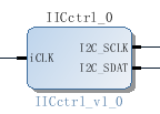
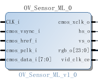
Figure 1. IIC Controller IP Figure 2. OV7670 Image Capture IP
2.2.2. Image Processing Module
Image enhancement is an IP core that comes with the Vivado tool from Xilinx, which integrates the functionality of multiple IP cores from older versions, including image enhancement, noise suppression, and halo suppression. As shown in Figure 3.
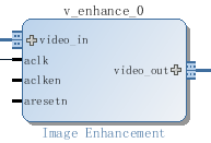
Figure 3. image enhancement IP
We remove the function of the control part of AXI-Lite, and only retain the image processing function of the PL part, which can change the processing intensity and processing effect by directly setting parameters. Just plug in the Video_in and Video_out the core ACLK signal.
2.2.3. Image handling Module
The design in this article is designed for the image processing part of the software, so the captured video stream information needs to be stored in DDR so that the software can read it. Generally speaking, there are two ways to transfer images: VDMA and DMA, and in this paper, the more convenient and fast VDMA method is adopted. As shown in Figure 4.
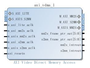
Figure 4. VDMA
VDMA stands for AXI Video Direct Memory Access. This IP is often featured in video-related designs, and has a similar status to DMA, but unlike VDMA, it is a module that specializes in providing high-speed storage access to video streaming data. Video data is accepted via the AXI-Stream protocol, while control signals. e.g. frame buffer size, DMA function on and off, etc. are accessed via AXI-Lite from other interfaces.
VDMA has two DMA paths, the S2MM path maps the input AXI4-Stream video stream to a specified framebuffer, while the MM2S does the opposite, outputs the frame buffer to an AXI4-Stream video stream. Figure 5 illustrates the basic principle.
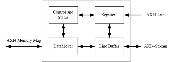
Figure 5. VDMA Functions and schematics
2.2.4. Image Output Module
The image output interface uses the VGA interface and uses Displayctrl IP. See Figure 6.
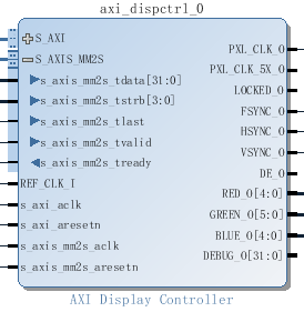
Figure 6. Displayctrl IP
The IP accepts video stream data from the MM2S side of the VDMA and is controlled by Zynq through the S_AXI side. The output interface needs to connect to several data required by the VGA, including the row refresh HSYNC_0, field refresh VSYNC_0, and the red, green, and blue output RED_0 [4:0], GREEN_0 [5:0], and BLUE_0 [4:0].
It is important to note that the IP core only accepts 32-bit ARGB signals, while we acquire 24-bit RGB signals on the acquisition and transport side. According to the concept of ARGB's medium transparent bit, we spliced 8 bits of transparency on the video stream before it flows into Displayctrl, that is, all "0". These 8-bit results do not affect the image we capture, but it does affect whether Displayctrl can output correctly.
2.2.5. Overall System
As mentioned in the above section of this article, the PL part of this design is divided into four parts: input module, processing module, handling module and output module, plus PS part, which together constitute a complete underlying hardware system. Figure 7 shows the system principle.
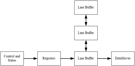
Figure 7. Schematic diagram of the system principle
The handling module is the core of the whole system, and it interacts with the processing and output modules to complete the image acquisition and output work. By interacting with the Zynq core, the video stream is delivered to DDR and removed.
Use Vivado's built-in Block Design tool to design the underlying hardware, and perform simulation, synthesis, and placement and routing, as shown in Figure 2-8. From left to right, there is the acquisition module, the processing module, the handling module and the output module.
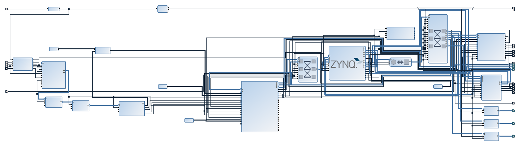
Figure 8. Block Design
As we mentioned earlier, VDMA and Displayctrl are controlled by Zynq, which means that these two IPs must be driven by software to work properly, so we use the SDK tools that accompany Vivado to write the drivers.
Use the "Xil_Out32" function to write the number to the registers corresponding to the VDMA and Displayctrl addresses. In the system.hdf of the SDK, we can find the starting address of the hardware, and write the corresponding data to each address according to the function of the corresponding register from the IP core introduction on the Xilinx official website to achieve the corresponding function. In this article, we'll use the most basic features.
2.3. Linux
In this article, boot Linux from the board, select the SD card boot mode, and configure Zybo to boot on SD card and power on USB.
2.3.1. The boot process of Linux
After the system is powered on, in non-JTAG mode, the PS side will first configure the system, and the system will first run the code in the BootROM to complete the initialization of hardware devices such as SD card, NAND, NOR, and Quad-SPI, and the DDR controller will be initialized after Stage 1.
The BootROM execution process is also responsible for loading the boot image of Stage1. The system supports multi-level loading of user-initiated images, and when the Stage1 process is executed, the user code will have control over the entire system.
The boot source of the system is selected by the external pins, that is, the BootROM loads the boot image of Stage 1 from different external devices according to the configuration of the external pins.
FSBL is the boot program after the boot of BootROM, FSBL mainly completes the initialization of the PS side, the configuration of the PL, the system can also not configure the PL part, load the second stage of the boot program SSBL to the memory space. The peripherals are initialized first, and then the image is booted from the SD card, and the FSBL stage code is loaded into the on-chip memory for execution.
This phase of SSBL is mainly responsible for the initialization of the relevant system and the preparation for the loading of the operating system. When the system is powered on, the operating system is not in memory, but another program is needed to initialize the system and load the operating system into memory, and the boot phase in this system is the SSBL phase. In this article, the system is running the Linux operating system, and its SSBL is U-boot. When running FSBL, the system loads U-boot to RAM to run, and U-boot (a function of U-boot) provides the hardware initialization part for completing the Linux kernel before booting, and loads the Linux kernel into memory to run. At the same time, U-boot also provides many user instructions, read and write memory, Flash, USB devices, etc.
After the system is booted through the SSBL phase, the system starts to run the Linux operating system. Figure 9 shows a common partition organization for embedded Linux on the Zynq-7000 platform.
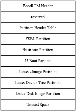
Figure 9. Linux mirror structure
2.3.2. Linux Environment setup
To build and compile the embedded Linux system environment, the first step is to install the cross-compilation environment The cross-compilation environment for the Zynq-7000 platform is arm-xilinx-Linux-gnueabi-gcc, which is used to compile developed drivers and applications, as well as various library functions, into executable code that is consistent with the Zynq-7000 instruction set.
• Compile U-boot
Embedded operating systems require bootloader booting to run in the system's memory, the FSBL process. When booting embedded operating systems, U-boot (Universal Boot Loader) is often used [18]. U-boot supports the boot of a variety of embedded operating systems, including Linux, and is widely used in various embedded systems due to its open source code, high stability and reliability, and flexible configuration[19]. In this article, U-boot is chosen as the bootloader for the embedded operating system.
Compiling u-boot will generate several related system files in the directory of that path.
Run the following command in the VM:
make CROSS_COMPILE=arm-xilinx-Linux-gnueabi- zynq_Zybo_config
gvim ./include/configs/zynq-common.h
gvim ./include/configs/zynq_Zybo.h
Update config to make it read ramdisk,sdboot will be
"sdboot=if mmcinfo; then "
"run uenvboot; "
"echo Copying Linux from SD to RAM... && " \
"load mmc 0 ${kernel_load_address} ${kernel_image} && " \
"load mmc 0 ${devicetree_load_address} ${devicetree_image} &&" \
"bootm ${kernel_load_address} - ${devicetree_load_address};"\
"fi\0" \
make ARCH=arm CROSS_COMPILE=arm-xilinx-Linux-gnueabi-
Finally, change the resulting executable file u-boot to a format that can be recognized by xilinx's SDK tools.
mv u-boot u-boot.elf
• Compile Linux Kernel and Device Tree
The Linux source code needs to be configured according to the system, and the system file image needs to be made after compilation, and the system file image needs to be put into the SD card or Flash during the actual runtime, and booted into the system memory through U-boot when the system starts.
Before compiling the kernel source code, the source code needs to be configured to meet the hardware requirements of the system.
root > make ARCH=arm digilent_zed_deconfig
Compile the Linux kernel.
make ARCK=arm CROSS_COMPILE=arm-xilinx-Linux-gnueabi-defconfig
make ARCH=arm CROSS_COMPILE=arm-xilinx-Linux-gnueabi-menuconfig
gvim ./arch/arm/kernel/setup.c
pr_info("Booting Linux on physical yeranCPU 0x%x\n", mpidr);
gvim ./init/main.c
make ARCH=armCROSS_COMPILE=arm-xilinx-Linux- gnueabi- UIMAGE_LOADADDR=0X00008000 uImage
make ARCH=armCROSS_COMPILE=arm-xilinx-Linux- gnueabi- LOADADDR=0X00008000 uImage
cp ./arch/arm/boot/uImage /mnt/
After the compilation is successful, the uImage file will be generated.
The default device tree source file is in the digilent-zed.dts directory in the arch/arm/boot/dts directory. Before compiling the device tree source file, you need to modify the device tree source file of the system. The controlled custom IP core used in this design, i.e., Displayctrl, needs to be described in the Devicetree.
With the description of the upper layer, we have obtained the three files that are necessary to boot Linux from the SD card, namely Boot.bin/uImage/devicetree. Put these three files into the SD card, insert the SD card into the card slot on the Zybo board, power on, and open Zybo to start Linux. Using the serial port tool, set the baud rate to 115200. We will be able to see the Linux boot successfully as shows in Figure 10.
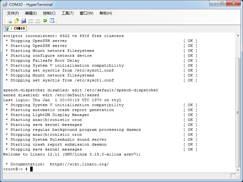
Figure 10. Linux Boot
2.4. mmap
Now we need to drive these low-level hardware in the same way you drive VDMA and Displayctrl in the SDK. However, Linux does not support direct reading and writing of registers corresponding to the underlying hardware address space, so we introduced mmap.
2.4.1. mmap schematic
mmap maps a file or other object (such as an address in this case) into memory space. As shown in Figure 11, these files (or others) are mapped to multiple pages, and if the size of the file is not the sum of the sizes of all pages, the unused space on the last page will be zeroed. mmap plays an important role in the user-space mapping invocation system.
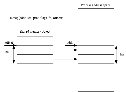
Figure 11. mmap
In our design, mmap will give the underlying address a new virtual address and store it in the memory space, and the original driver only needs to use the new address.
2.4.2. function
In the Linux environment, we need to use the following functions to map the address of the underlying hardware in the mmap mode.
• The header file used by the function
<sys/mman.h>
• Function archetypes
void* mmap(void* start,size_t length,int prot,int flags,int fd,off_t offset);
int munmap(void* start,size_t length);
After we use the virtual addresses mapped by these mmaps, we need to free up this part of the space used to store the virtual addresses, otherwise there will be problems. You can use the mmap and munmap functions in turn to map and cancel the address in the Linux system.
2.5. OpenCV
Int this section, we are going to install OpenCV based on Linux environment.
2.5.1. cmake
OpenCV 2.2 or later versions require Cmake to generate makefile files, so you need to install cmake first. It is relatively simple to install cmake under ubuntu, enter the command:
sudo apt-get install cmake
If you feel that the built-in version does not meet the requirements, you can download the installation package. In this article, the download has been compiled, so you only need to unzip it to the desired directory to use:
tar zxvf cmake-2.8.10.2-Linux-i386.tar.gz –C /usr/local/
Set environment variables:
sudo gedit /home/emouse/.bashrc
export PATH=$PATH:/usr/local/cmake-2.8.10.2-Linux-i386/bin
Enter the command to check the version and test whether the installation is successful:
cmake --version
The output information of the serial port is:
cmake version 2.8.10.2
2.5.2. OpenCV Installation
To install OpenCV in the Linux environment, first install libgtk2.0-dev and pkg-config, otherwise there will be problems with the later compilation and running program, enter the command:
apt-get install libgtk2.0-dev
apt-get install pkg-config
Download OpenCV, unzip it, get the folder OpenCV-2.4.3, and create a new folder OpenCV-x86 here as the PC compilation directory.
Use the Cmake directive to generate the makefile file directly:
cmake-DCMAKE_BUILD_TYPE=RELEASE-DCMAKE_INSTALL_PERFIX=/home/Opencv
After that, you can enter the OpenCV-x86 directory to view the Makefile file, and pay attention to whether the generation time of the file is consistent with the generation time just now, so as to determine whether the Makefile file is generated correctly according to the settings of our configuration parameters.
Run make and make install in the OpenCV-x86 folder to complete the compilation and installation process.
After the installation is complete, we need to configure the environment variables related to the system:
sudo gedit /etc/ld.so.conf.d/opencv.conf
Add the following to the end of the file:
/usr/local/lib
Finally configure the library and change the environment variables:
udo ldconfig
sudo gedit /etc/bash.bashrc
At the end of the file, add:
PKG_CONFIG_PATH=$PKG_CONFIG_PATH:/usr/local/lib/pkgconfig
export PKG_CONFIG_PATH
At this point, the installation process of OpenCV is complete, and we can use the built-in routine under OpenCV to test the installation results.
2.6. Software-based image process
Building on the previous content, we'll start working on the software processing part. In the software processing part, we need to solve several problems of compiling and running C/C++ files on the board, and then we will use the image interception algorithm to perform software processing on the image.
2.6.1. Image Processing flow
In the previous chapter, it was mentioned that Linux cannot directly read the address of the underlying hardware, and proposed an mmap solution, which will be used in this chapter to map the underlying address through mmap so that OpenCV can read the image information that has been written into DDR. After the mmap and the underlying address are assigned, OpenCV reads the underlying DDR frame by frame. After reading another frame, the format is converted to Mat format and image processing is performed. After processing, the image is converted back to ARGB format and written back to DDR. At this point, one frame is processed, and each frame after that goes through this process to link the image into a complete video.
Note that in the hardware path, VDMA will read and write the same pool area in DDR, and after the introduction of OpenCV software processing, in order to avoid conflicts between images before and after processing, different pool areas need to be set for VDMA to read and write. This is shown in Figure 12.
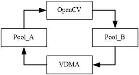
Figure 12. OpenCV/VDMA
Based on the original design, it is sufficient to set the S2MM part to Pool_A and the MM2S part to Pool_B. That is, the whole process is that the S2MM end of VDMA sends the video stream to the Pool_A DDR, and OpenCV takes the video stream from the Pool_A, processes it by algorithms, and then returns the processed video stream to the Pool_B, constituting the entire video processing loop.
2.6.2. Compilation
OpenCV's library functions are very rich in content, supporting C/C++, Python and other languages. The code for the processing part of this article is .cpp, while the code for the mmap part is .c. In order to be able to mix and compile the two languages in the onboard Linux environment, a new Makefile file was written to adapt to the design.
• extern "C"
In order for the .c header files and functions to be referenced in .cpp files, the extern keyword needs to be used. When it is used in conjunction with "C" (e.g. extern "C" void fun(int a, int b)), this keyword tells the compiler to translate the function name of the function according to the rules of C when compiling the function name of the function according to the rules of C instead of C++, and the rules of C++ will make the name fun unrecognizable when translating the function name, because of C++Support for overloading of functions, which is different from C. In this article, the main function of the .cpp is used, and the other functions are .c functions.
• Makefile
GCC is a sub-project of the GNU Project, originally a compiler for compiling the C language. With the growth of the GNU Project, GCC has become a family of GNU compilers capable of compiling languages such as C, C++, Ada, Object C, and Java, as well as > cross-compilation across hardware platforms. G++ is a compiler specifically designed to compile C and C++ languages. C and C++ languages are constantly evolving, and in order to keep the latest features of compatible programming languages, developers usually choose GCC to compile the source code written in C and G++ to compile the C++ source code. This article also takes this approach.
To install the GCC/G++ compiler, the installation command is as follows:
yum install make
yum install gcc
yum install gcc-c++
In the Makefile file, you need to use GCC to compile C code and G++ to compile C++ code, and the main modifications of the file are as follows:
CCC = gcc
CPPCC = g++
LINK = g++
${BIN_TARGET}:${OBJ}
$(LINK) $(OBJ) -o $@ $(LDFLAGS)
${DIR_OBJ}/%.o:${DIR_SRC}/%.c
$(CCC) $(CFLAGS) -c $< -o $@
${DIR_OBJ}/%.o:${DIR_SRC}/%.cpp
$(CPPCC) $(CPPFLAGS) $(CXXFLAGS) -c $< -o $@
2.6.3. Image format conversion
As mentioned in the previous section, the video stream in the underlying hardware is in 32-bit ARGB format, which is suitable for image capture and playback devices. However, OpenCV generally stores images in a different format, and generally uses the Mat type as the container for the image.
Basically, Mat is a class that consists of two data parts: a matrix header (which contains information such as matrix size, storage method, storage address, etc.) and a pointer to a matrix that stores all pixel values (different matrices can be different dimensions depending on the storage method chosen). The size of the matrix header is constant, but the size of the matrix itself will vary from image to image, and is usually orders of magnitude larger than the size of the matrix header. In contrast to traditional IplImage's C struct types, Mat doesn't have to manually open up space for it, and frees up space as soon as it's not needed.
In the MAT format, the three-channel image is arranged as BGR, which is different from the order of the three colors in 32-bit ARGB. Therefore, these two format types need to be converted to each other. In this paper, the RGB is reorganized into the form of BGR by shifting and splicing, and the format conversion is completed. Before OpenCV writes back the image, the processed image is re-stitched into the ARGB format to complete the image format conversion.
3. Results and Analysis
3.1. Image Pathway
After writing the driver, download the .bit file to the board, compile and run the software part, connect the VGA interface to the monitor, and obtain the image captured by the camera. Figure 13 shows the image captured by the OV7670.
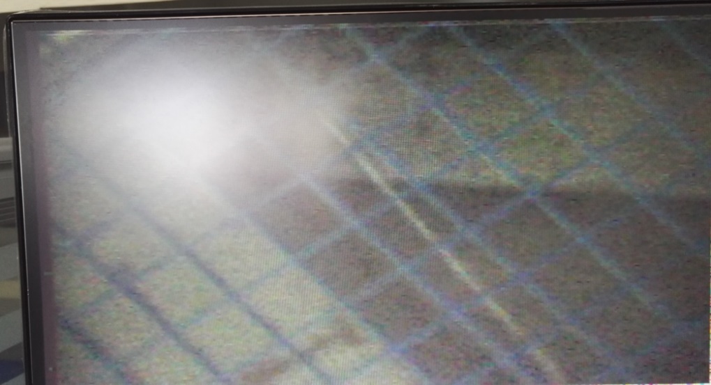
Figure 13. Image captured by OV7670
The image size is 640*480, the refresh rate is 30 frames, and the image appears in the upper left corner of the screen, which is conducive to our post-processing software. In a later section, we will look at the effect of image position on OpenCV processing. After the original image is processed, the enhanced image obtained is shown in Figure 14.
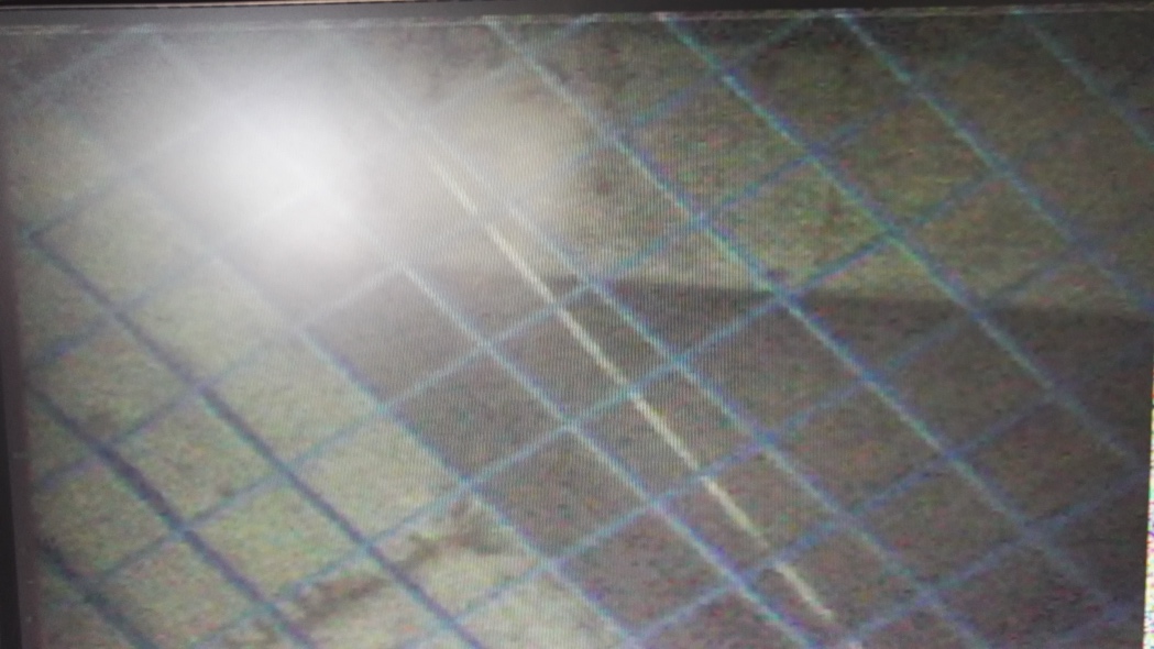
Figure 14. Image enhancement
Adjusting the parameter settings of image enhancement in Vivado to obtain the result after image enhancement, you can see the obvious difference in detail of the image before and after processing. The enhanced image is noticeably detailed, with a "smeared" feel at the edges of the details.
3.2. OpenCV image processing
Use the Rect function in the OpenCV library to take a screenshot of the image, and the original function is as follows:
Rect(x,y,width,height)
The member variables x, y, width, and height are the coordinates of the upper-left corner and the width and height of the rectangle, respectively. Commonly used member functions are Size() to return a Size, area() to return the area of the rectangle, contains(Point) to determine whether the point is in the rectangle, inside(Rect) to determine whether the rectangle is in the rectangle, tl() Returns the coordinates of the upper left corner point, and br() returns the coordinates of the lower right corner.
In this design, the 640*480 image of the original image is cut into 640*240. The original image is shown in Figure 15.
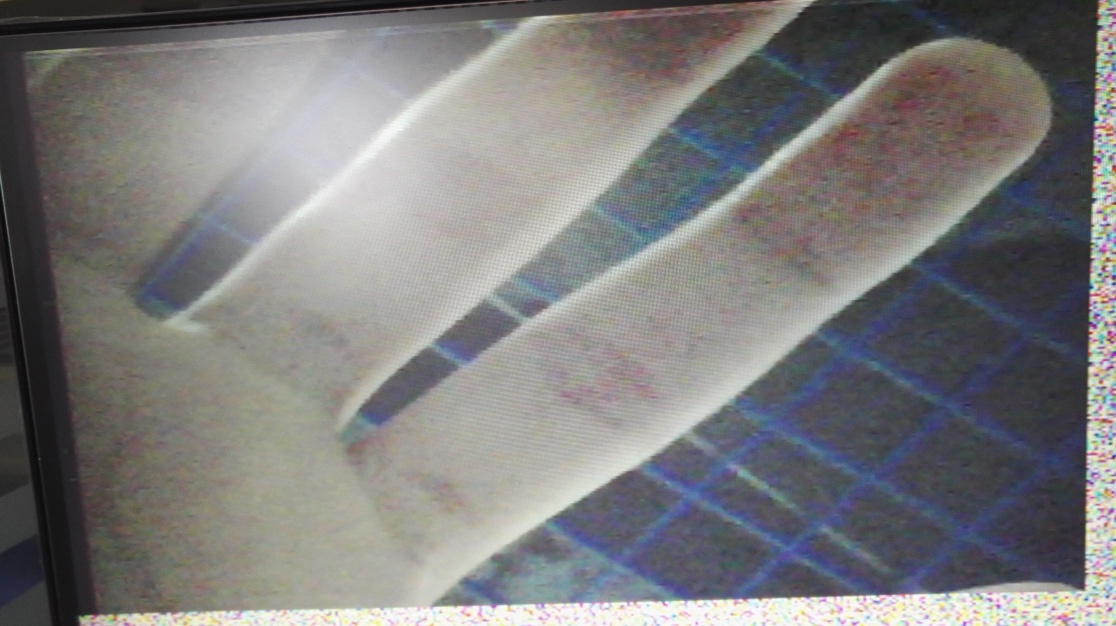
Figure 15. Original image. The original image that has been transported by OpenCV is the same as the original image we got before.
Figure 16. An image that has been processed by an image capture algorithm. The image after the image capture algorithm is 640*240 resolution
4. Conclusion
Both heterogeneous concepts and embedded image processing are attracting more and more attention. This paper proposes a heterogeneous architecture in embedded systems, which uses software and hardware co-processing to process real-time images, which not only meets the requirements of computing speed, but also takes into account the flexibility and power consumption of the system, which is a very practical way of embedded real-time image processing. Compared to traditional image processing methods, the advantages are obvious.
In order to build a heterogeneous embedded image processing system, the following aspects have been completed in this paper:
• Vivado was used to build the underlying hardware system, complete the basic real-time image processing path, and select the appropriate hardware processing IP core.
• The porting of Zybo's on-board Linux system was carried out, and the writing of the board driver was completed according to the characteristics of the Linux system.
• Finally, the installation and use of OpenCV was completed, the appropriate software image processing algorithm was selected, and some important details involved were solved.
There is still a lot to be explored in the research of embedded solutions, and even the way to implement the same solution is flexible and diverse. Due to the constraints of various conditions, the following work needs to be done in order to continue the research on embedded image processing schemes in this paper:
• Evaluation of hardware and software processing efficiency. The different processing characteristics and processing advantages of software and hardware are judged through the effect and time of different implementations of the same algorithm software and hardware, and more suitable software and hardware algorithms are selected to theoretically accelerate the process of image processing.
• OpenCV read efficiency issues. The OV7670 used in this article has a refresh rate of 30 frames, while the OpenCV read-processed image is lower than that. This is due to the limitations of the read and write methods and the performance of the platform. It can be improved in future designs.
• In view of the characteristics of embedded processing, it should be the focus of future research to study its processing ability for various existing image processing.
References
[1]. Abhijeet Kumar, Rachana Rajpal, Harshad Pujara, et al. Universal Interface on Zynq SoC with CAN, RS-232, Ethernet and AXI GPIO for Instrumentation & Control[J]. Fusion Engineering and Design, 2016.
[2]. Qiang Wu. Research on the High Speed Image Transfer based on the Zynq-7000[C]. Proceedings of 2016 2nd Workshop on Advanced Research and Technology in Industry Applications, 2016 : 5.
[3]. Jiao Zaiqiang Design and implementation of embedded digital image processing system based on Zynq-7000[D]. Taiyuan University of Technology, 2015
[4]. Ning Ma. High Efficiency On-Board Hyperspectral Image Classification with Zynq SoC[C]. Proceedings of 2016 7th International Conference on Mechatronics and Manufacturing, 2016 : 6.
[5]. Pan Ruijie, Chen Biao, Liu Xi'an The history and development of programmable logic devices[J]. Electronics & Packaging, 2008, 08(9): 44-48
[6]. Wang Yu Research on embedded real-time image processing system based on Zynq-7000[D]. Huazhong University of Science and Technology, 2015
[7]. Yang X, Luo J, Hao S U, et a1. High-Speed Image Acquisition and Real-time Processing System Based on Zynq-7000[J]. Electronic Science & Technology, 2014.
[8]. Huang Shuxian Design Method of Visual Image Processing System Based on MATLAB Platform[J]. Journal of Yangtze University: Zike Edition, 2005, 2(4): 158-160
[9]. Wang Qiang Design and implementation of a real-time image processing hardware platform[D]. Beijing Jiaotong University, 2009
[10]. Liu Angju Research on hardware platform of real-time image processing system[D]. Beijing Jiaotong University, 2008
[11]. Wu Ying Design of DSP-based image acquisition and processing system[D]. Harbin Engineering University, 2009
[12]. Sun Rui Development of video image processing experimental platform[D]. Harbin Institute of Technology, 2009
[13]. Yang Huili Design of image processing platform based on embedded system[D]. Hebei University of Science and Technology, 2009
[14]. Wang J X, Yin C L. Embedded Color Image Enhancement System Based on DSP and FPGA[J]. Chinese Journal of Liquid Crystals & Displays, 2013, 28(3): 459-463.
[15]. Wu Mingqi Performance study and comparison of typical embedded operating systems[D]. East China Normal University, 2015
[16]. Xue Yan, Jiang Hao Application of remote monitoring system based on ARM high-speed data acquisition[J]. Process Automation Instrumentation, 2008, 29(10): 40-43
[17]. Wu Fan Research on object tracking system based on ARM embedded platform[D]. Wuhan University of Science and Technology, 2009
[18]. Sea Ice Research and implementation of media digital signal processor simulator[D]. Zhejiang University, 2014
[19]. Yuan Qiulin Portable development and application of embedded Linux system based on ARM9 platform[D]. Northwest Normal University, 2014
Cite this article
Meng,Y. (2024). Design of an image processing system for heterogeneous computer architectures. Applied and Computational Engineering,67,350-367.
Data availability
The datasets used and/or analyzed during the current study will be available from the authors upon reasonable request.
Disclaimer/Publisher's Note
The statements, opinions and data contained in all publications are solely those of the individual author(s) and contributor(s) and not of EWA Publishing and/or the editor(s). EWA Publishing and/or the editor(s) disclaim responsibility for any injury to people or property resulting from any ideas, methods, instructions or products referred to in the content.
About volume
Volume title: Proceedings of the 2nd International Conference on Software Engineering and Machine Learning
© 2024 by the author(s). Licensee EWA Publishing, Oxford, UK. This article is an open access article distributed under the terms and
conditions of the Creative Commons Attribution (CC BY) license. Authors who
publish this series agree to the following terms:
1. Authors retain copyright and grant the series right of first publication with the work simultaneously licensed under a Creative Commons
Attribution License that allows others to share the work with an acknowledgment of the work's authorship and initial publication in this
series.
2. Authors are able to enter into separate, additional contractual arrangements for the non-exclusive distribution of the series's published
version of the work (e.g., post it to an institutional repository or publish it in a book), with an acknowledgment of its initial
publication in this series.
3. Authors are permitted and encouraged to post their work online (e.g., in institutional repositories or on their website) prior to and
during the submission process, as it can lead to productive exchanges, as well as earlier and greater citation of published work (See
Open access policy for details).
References
[1]. Abhijeet Kumar, Rachana Rajpal, Harshad Pujara, et al. Universal Interface on Zynq SoC with CAN, RS-232, Ethernet and AXI GPIO for Instrumentation & Control[J]. Fusion Engineering and Design, 2016.
[2]. Qiang Wu. Research on the High Speed Image Transfer based on the Zynq-7000[C]. Proceedings of 2016 2nd Workshop on Advanced Research and Technology in Industry Applications, 2016 : 5.
[3]. Jiao Zaiqiang Design and implementation of embedded digital image processing system based on Zynq-7000[D]. Taiyuan University of Technology, 2015
[4]. Ning Ma. High Efficiency On-Board Hyperspectral Image Classification with Zynq SoC[C]. Proceedings of 2016 7th International Conference on Mechatronics and Manufacturing, 2016 : 6.
[5]. Pan Ruijie, Chen Biao, Liu Xi'an The history and development of programmable logic devices[J]. Electronics & Packaging, 2008, 08(9): 44-48
[6]. Wang Yu Research on embedded real-time image processing system based on Zynq-7000[D]. Huazhong University of Science and Technology, 2015
[7]. Yang X, Luo J, Hao S U, et a1. High-Speed Image Acquisition and Real-time Processing System Based on Zynq-7000[J]. Electronic Science & Technology, 2014.
[8]. Huang Shuxian Design Method of Visual Image Processing System Based on MATLAB Platform[J]. Journal of Yangtze University: Zike Edition, 2005, 2(4): 158-160
[9]. Wang Qiang Design and implementation of a real-time image processing hardware platform[D]. Beijing Jiaotong University, 2009
[10]. Liu Angju Research on hardware platform of real-time image processing system[D]. Beijing Jiaotong University, 2008
[11]. Wu Ying Design of DSP-based image acquisition and processing system[D]. Harbin Engineering University, 2009
[12]. Sun Rui Development of video image processing experimental platform[D]. Harbin Institute of Technology, 2009
[13]. Yang Huili Design of image processing platform based on embedded system[D]. Hebei University of Science and Technology, 2009
[14]. Wang J X, Yin C L. Embedded Color Image Enhancement System Based on DSP and FPGA[J]. Chinese Journal of Liquid Crystals & Displays, 2013, 28(3): 459-463.
[15]. Wu Mingqi Performance study and comparison of typical embedded operating systems[D]. East China Normal University, 2015
[16]. Xue Yan, Jiang Hao Application of remote monitoring system based on ARM high-speed data acquisition[J]. Process Automation Instrumentation, 2008, 29(10): 40-43
[17]. Wu Fan Research on object tracking system based on ARM embedded platform[D]. Wuhan University of Science and Technology, 2009
[18]. Sea Ice Research and implementation of media digital signal processor simulator[D]. Zhejiang University, 2014
[19]. Yuan Qiulin Portable development and application of embedded Linux system based on ARM9 platform[D]. Northwest Normal University, 2014