


1. Introduction
As time develops, people have more and more demands for structures and their requirements are getting higher and higher. Truss structure thus breeds development and is gradually widely used in different engineering structures. Truss structure is a kind of stable structure connected by linear members (usually rods) [1], which is light in weight and large in span, and has been used in a large number of large-scale projects such as large-scale bridges, airports, space stations, etc. [2], and with the continuous development of architectural structure, truss structure has been becoming more and more heavy, and it has become an indispensable part of the modern architecture. However, how to effectively design and optimise while meeting engineering requirements has become an urgent problem for engineers.
Design is an important part of bridge construction, directly affecting the bridge's safety, stability and service life [3]. When carrying out the design, engineers need to consider different environmental and human factors, such as geological formations, climatic environments, through-traffic conditions, etc., to ensure that the final design scheme can adapt to various complex scenarios and conditions. At present, the construction of the world's bridges is varied, and the length of the bridges is also increasing. Such as the world's longest cable-stayed bridge girder is China's Sutong Yangtze River Bridge, the total length of 1088m, the longest suspension bridge Japan Akashi Kaikyo Bridge (1991m), the longest cantilever bridge in the United States, the San Francisco Bay Bridge (1618m), and T.Y. Lin has put forward a proposal to build a double-span 5,000-metre suspension bridge across the Straits of Gibraltar [4]. The length of the bridge is increasing, therefore, the consideration of material and cost should not be neglected, and the optimisation of the overall design of the truss is crucial and has certain practical significance.
In engineering design, as the requirements of engineering structures continue to increase and the engineering structures continue to change, the structures are optimised by deterministic design methods in order to meet the requirements of economy and safety. Structural optimisation can be divided into three main stages in the form of design variables: size optimisation, shape optimisation and topology optimisation [5]. The topological optimisation model is optimised for several structural properties and parameters, such as the volume of the material used, the strain energy, and the compression modulus. The design variables are the parts that are adjusted and optimised during the structural optimisation process, among them are the dimensions of the bars, the position of the nodes and the form of contact between the bars [6]. The optimal design of structures is an important research topic and a problem that needs to be solved by engineers [7], especially in terms of maximising the effect of the materials at the limit level, so it is necessary to study the optimal design of truss structures [8]. Optimal design can make the overall structure meet the design requirements, minimise the use of materials, reduce the overall material cost, and improve the strength, stiffness and durability of the structure [9].
This paper aims to briefly design a truss for a site environment and propose a feasible optimisation plan. Firstly, the basic truss combination that meets the loading and structural requirements is determined and the axial force of each rod is calculated using a structural mechanics solver, which in turn calculates the amount of each rod. Then, on the basis of the basic truss scheme, unfavourable bars in construction were removed and preliminary optimisation design was carried out to reduce the material usage. Taking into account the existing building experience, the second design scheme is proposed and further optimised. Finally, by comparing the four schemes, the direction in which the usage can be reduced is analysed, such as reducing the beam span, using short bars and adopting parallel truss design. The arrangement of truss members is optimised to find the minimum amount of material used under the condition that it meets the loading requirements. The optimal design can satisfy the green concept advocated today and improve the economic efficiency of truss structure.
2. Methodology
A truss bridge is a common structure usually consisting of multiple trusses. Each truss consists of upper and lower chords and diagonal rods, forming a stable triangular structure. The top and bottom chords are located at the top and bottom of the truss and mainly bear the tension and pressure of the bridge, while the diagonal rods are connected between the top and bottom chords to support and reinforce the whole truss structure.
The basic structural design of truss bridge minimises material consumption and ensures the structure's overall strength, stiffness and stability. In the actual engineering design, many external and internal factors are taken into consideration, including: site environment, material performance parameters, human influence, etc. Therefore, the design of truss bridge is a complicated and precise project. Therefore, the truss bridge design is a complicated and precise project, which needs to fully consider various factors to achieve the design objectives of economy, practicality, aesthetics and safety. The structural design of rod bridge involved in this paper only considers to satisfy the additional loads, and other wind loads, snow loads, etc. are not given consideration.
In order to achieve the truss bridge to meet the load requirements while minimising the material usage, this paper carries out the basic mechanical analysis and optimal design with the help of structural mechanics solver.
Structural Mechanics Solver [10], abbreviated as SM Solver (hereinafter referred to as the solver) is a software developed by Tsinghua University that can perform computer-aided analysis and calculation of structures. Its interface is simple, you can set the nodes, units, and then load distribution, you can establish a two-dimensional structural model that meets the required requirements, so as to obtain the required axial force as shown in Figure 1, the red part of the figure indicates that the rod is subjected to the role of tensile stress, the blue part of the role of the received compressive stresses, and the absence of internal force indicates that the rod has no role in the force, but play a role in ensuring that the overall structure is in the geometrically invariant system. The structural mechanics solver can be used to accurately determine the structural strength of the structure. The Structural Mechanics Solver can be used to solve all of the brief problems involved in structural mechanics accurately.
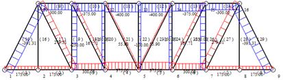
Figure 1. Structural Mechanics Solver for Axis Striving Solutions
The research steps in this paper begin with setting up the nodes, units and load distribution in turn in the structural mechanics solver, after which the software is used to carry out a geometric composition analysis to ensure that the structure is a geometrically invariant system. Under the premise of ensuring the geometric invariance of the system, the axial force of each rod is output.
After that, the amount of material used to calculate the bar, the rebar material mainly reflects the tensile properties, in tension by the formula for calculating the cross-sectional area of the bar
\( A=\frac{F_N}{\sigma} \) (1)
where A denotes the cross-sectional area of the bar; FN denotes the tensile stress to which the bar is subjected; and σ denotes the permissible strength of the material in kPa.
When a bar is under pressure, it is firstly subjected to a compressive stability calculation, i.e. Euler's formula for calculation [11]
\( P_{cr}=\frac{\pi^2EI}{l^2} \) (2)
E is the modulus of elasticity of the material in kPa; I is its polar moment of inertia; and l is the length of the rod in m.
\( I=\frac{1}{12}(d^4 - (d - 2t)^4) \) (3)
d is the side length of the cross-section of the material (square barrel design of its width and height are equal), the unit m; t is the wall thickness of the cross-section, the unit mm.
Where t is small compared to d, often t for d 1/18 ~ 1/5, so in the calculation of the polar moment of inertia I can be simplified calculation, then there are
\( (d - 2t)^4=(d - 2t{)^2}^2=(d^2 - 4dt+4t^2)^2\approx d^4 - 8td^3+16t^2d^2 \) (4)
Euler's formula by simplification
\( P_{cr}=\frac{\pi^2EI}{l^2}=\frac{\pi^2E}{l^2}\frac{2td^3}{3} \) (5)
The side lengths d of the bars are formulated so that their compressive load capacity can be greater than the actual pressure they are subjected to, after which they are subjected to material usage calculations, i.e., the product of the perimeter and the thickness. The cross-sectional area is
\( A=4td \) (6)
And at the same time in accordance with the tensile condition when the calculation, compare the size of the two calculated cross-section area, take the larger value of the two.
After the abutment part of the pressure stability check, calculate the amount of material required for the abutment, the abutment part of the force according to the state of pressure, according to the analysis of the pressure of the steps of the material used in its calculation. The final sum of all the rods, the structure of the overall amount of material.
3. Results
3.1. Research target
The width of a river is 85m, the bottom of the river is 25m above the ground surface, and its horizontal surface is 15m above the earth's surface. now a truss bridge is designed to cross the river horizontally. The lower part of the bridge is required to leave space for boats with a height of 5m and a width of 50m, and for the sake of overall aesthetics, the height of the upper part shall not exceed 8m, and the structural load of the whole bridge shall meet 150kN/m. The material cross section of the truss is designed as a square cylinder to ensure the wall thickness of 10mm, the permissible strength of the material is 400MPa, the elasticity modulus is 200GPa, and the smallest size of the cross section is 0.01m2, which needs to be taken into account in designing. The compressive stability of the bars needs to be considered. The final design of truss bridge structure should achieve specific stability and economy.
3.2. Experimental programme
Two main experimental approaches, the under-bearing and the combined under-bearing (hereafter referred to as combined), have been adopted and further optimised. The designed schemes are attached with piers and are based on the undercarriage design, which is continuously enriched.
The design of bottom-bearing truss structure means that the designed bridge deck is located in the lower part of the truss structure, and the upper truss carries the load. The design is relatively simple and the total number of bars used is less when the loading condition is satisfied, so the construction is convenient. However, in combination with actual engineering cases, when designing large span bridges, the use of submerged structure may result in local instability [12].
The combined truss structure design, which combines top-bearing and bottom-bearing design with two additional abutments, is more complicated and uses a larger number of rods than the truss structure design. Most of the rods involved are short rods, and the construction is more convenient. The overall design shows strong symmetry, and after the actual construction, it will have the symmetrical beauty of the building.
3.2.1. Bottom-loading type
The structural design using a bottom bearing truss is shown in Figure 2. A total of 28 rods are used in this scheme, and an abutment is designed at 16 nodes, which remains a square barrel design.
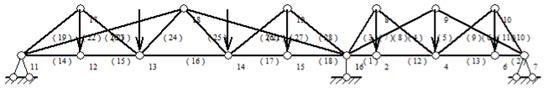
Figure 2. Bottom-loaded sketch
The left and right sides of the abutment are designed according to the simple support design, the span of the left truss is 55m, the right side is 30m. the highest truss is 8m. the length of the straight rods is 8m. this paper selects a few representative abbreviations to be shown in Table 1.
Table 1. Table of lengths of bottom-bearing bars (unit: m)
Rod end 1 |
Rod end 2 |
Length |
11 |
12 |
10 |
13 |
14 |
15 |
16 |
2 |
5 |
2 |
4 |
10 |
13 |
18 |
10.966 |
12 |
17 |
8 |
11 |
17 |
12.806 |
11 |
18 |
28.64 |
16 |
8 |
9.434 |
7 |
9 |
17 |
Both sets of trusses are symmetrical in design, and the overall design of the rods of both sets of trusses is similar, which can reflect the beauty of symmetrical design in the real construction. The total number of designed rods is less, and it is easier to weld in general.
The bending moment diagram of the truss design of this scheme is shown in Figure 3, the bending moment of the left end truss is obviously larger than that of the right end truss.Then it indicates that the left end truss structure receives a larger bending moment, so it may have a larger demand in terms of material usage.
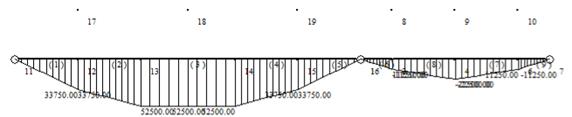
Figure 3. Downward bending moment diagram
This design structure meets the loading requirements, among which 12 rods are compression rods and 16 rods are tension rods. The abutment meets the compression stability calculation, and its supporting reaction force is 3375kN. The total amount is 5.772m3 after calculation, among which, the total amount of truss is 5.172m3, and that of abutment is 0.6m3.
3.2.2. Bottom-loaded optimisation
The structural design using a bottom-bearing truss is shown in Figure 4. A total of 36 rods are used and an abutment is designed, which is designed at 16 nodes and remains a square barrel design.
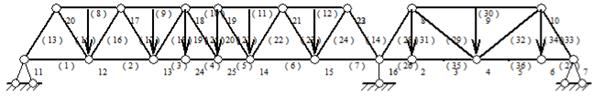
Figure 4. Optimisation sketch of the bottom-loading type
The left and right sides of the abutment are designed according to the simply supported girder, the left truss span is 55m, the right side is 30m, and the highest truss is 8m. two groups of trusses are designed according to the simply supported, the right side takes the symmetrical design, and the left side is the design of Pratt truss. In this paper, a few representative simplexes are shown in Table 2.
Table 2. Table of optimised rod lengths for bottom-loading (unit: m)
Rod end 1 |
Rod end 2 |
Length |
11 |
12 |
10 |
13 |
24 |
5 |
16 |
2 |
5 |
2 |
4 |
10 |
12 |
20 |
9.434 |
8 |
4 |
12.806 |
18 |
24 |
8 |
20 |
17 |
10 |
8 |
10 |
20 |
The number of rods on the left side of the rods of the truss as a whole is greater than that on the right side. In the real construction, it can reflect the beauty of symmetrical design. The total number of designed rods is relatively large, but most of them are rods, and it is easier to weld in the actual construction.
From the bending moment diagram of this scheme, Figure 5, it is found that the overall bending moment at the left end is still larger than that at the right end. Still, compared with the first scheme, the bending moment at the left end is significantly reduced. There will be a slight reduction in the material's ability to bear the bending moment requirements.
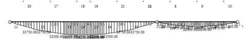
Figure 5. Optimised bending moment diagram for bottom bearing
This design structure meets the loading requirements, there are 14 rods are compression rods, there are 21 rods are tension rods, and there is also 1 zero rod attached. The abutment meets the compression stability check, and the support reaction force it provides is 3375kN. the total material usage of this scheme is 3.641m3, of which the total usage of truss is 3.041m3, and the usage of abutment is 0.6m3.
3.2.3. Combined
The structural design using top-bearing and bottom-bearing trusses is shown in Figure 6. A total of 33 rods are used and two piers are designed, the piers are designed at 4 nodes and 8 nodes respectively, which are still of square barrel design.
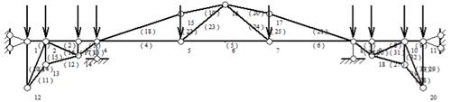
Figure 6. Combinatorial sketch
All three truss bridges are designed according to the simply supported girder design in the step-by-step design, the left and right truss spans are 15m, and the middle section truss is 55m. The highest truss is 8 m and the lowest out is 10 m below the ground surface. This paper selects several representative briefs, such as Table 3.
Table 3. Length of bonded bars (unit: m)
Rod end 1 |
Rod end 2 |
Length |
4 |
5 |
18 |
5 |
7 |
19 |
1 |
12 |
10 |
2 |
13 |
5 |
15 |
5 |
4 |
12 |
13 |
6.4 |
13 |
14 |
7.28 |
2 |
14 |
7.62 |
14 |
4 |
5 |
5 |
16 |
12.42 |
1 |
2 |
4 |
2 |
3 |
7 |
2 |
12 |
10.77 |
3 |
4 |
4 |
4 |
15 |
18.44 |
15 |
16 |
10.31 |
The overall truss bridge is symmetrical, with the left and right sides of the truss bridge adopting a top-loading design and the middle section adopting a bottom-loading design. And there are two additional piers. In the actual construction, the structure as a whole can present similar to the arch bridge, and the overall design appearance is more beautiful.
The combined bending moment diagram Figure 7 shows that the bending moment of the two end trusses is extremely small compared with the middle trusses, and the bending moment is greatly reduced compared with the bending moment diagrams shown in the previous two design structures. In this scheme, the required bending moment bearing capacity of the rods is small, and compared with this, the requirement for the materials is low, and the material usage can be saved.
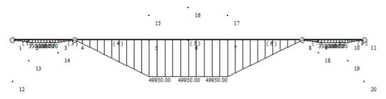
Figure 7. Combined bending moment diagram
The total amount of this design structure is 4.069m3 under the condition of meeting the loading requirements, among which the total amount of truss is 2.789m3 and the amount of abutment is 1.28m3. 14 rods are compression rods and 19 rods are tension rods. The piers satisfy the compression stability calculation, and the support reaction force provided by both piers is 5250kN.
3.2.4. Combined optimisation
Further optimisation of the design using the combined type is shown in Figure 8. A total of 41 rods are used, and two piers are still designed, which are designed at 4 and 8 nodes respectively, and are still of square barrel design.
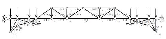
Figure 8 .Combined optimised design sketch
In the step-by-step design, all three truss bridges are designed as simply supported girders, with the left and right trusses spanning 15m and the middle section truss being 55m. The highest truss is 8 m and the lowest out is 10 m below the ground surface. this paper selects a few representative shorthand displays in Table 1.
Table 4. Combined optimised rod length table (unit: m)
Rod end 1 |
Rod end 2 |
Length |
23 |
24 |
8 |
4 |
21 |
9 |
5 |
7 |
19 |
22 |
5 |
12.04 |
22 |
15 |
9 |
15 |
16 |
9.5 |
4 |
22 |
12.04 |
The overall truss bridge is symmetrical, with the left and right sides adopting the top-loading design, while the middle section adopts the bottom-loading design, and is mostly made of short bars. And there are two additional piers. In the actual construction, the whole structure can be similar to the arch bridge hole, and the overall design appearance is more beautiful.
The bending moment diagram of this design does not change much compared to the optimised one, with a slight change in the middle section, where the bending moment diagram is more gentle and the bending moment does not increase continuously and linearly.
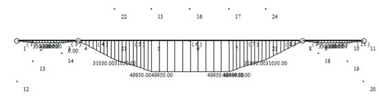
Figure 9. Combined optimised bending moment diagram
In this design structure, there are 16 rods as compression rods and 21 rods as tension rods, containing 3 zero rods under the condition of meeting load requirements. The abutment meets the compression stability calculation, and the support reaction force provided by both abutments is 5925kN. the total dosage is 3.464m3, of which the total dosage of truss is 2.132m3, and the dosage of abutment is 1.331m`.
4. Conclusion
After design comparison, it is found that in the case of meeting the load requirements, reducing the overall span of each section of the beam can effectively reduce the axial force of each rod, and reduce the maximum bending moment reflected therein as well as change the form of bending moment distribution, which can reduce the amount of material to achieve the purpose of optimising the design.
By comparing the two design schemes of the bottom-loaded type, it is found that although a large number of short members are used and the number of members is increased, the material consumption of the overall structure is reduced instead. This shows that in the design optimisation process of truss structure, the material consumption of the overall structure can be effectively reduced by using short members.
Taking into account the various elements of the programme, it was found that there are still some problems with realistic construction. Firstly, in the designed structure, there are longer bars and larger cross-section bars, which will pose a challenge in practice, and there is still room for further optimisation. Moreover, when considering the compression members, only approximate calculations were made, and the results obtained were only approximate values and not precise enough. In addition, the compression cases, including the piers, are analysed only according to the axial compression, and in the actual scenario there are other external factors that may have an impact.
In the actual construction, the proposed scheme can be used as a simple design reference, which can be used as a driving force to study and analyse how to further optimise the design of trusses. More in-depth analyses and adjustments may be required in the project to ensure the feasibility and efficiency of the design scheme.
References
[1]. Zhao T 2019 DOI:10.27104/d.cnki.ghbjy 2019.000130
[2]. Liu M 2021 Harbin Institute of Technology
[3]. Peng W, Shen J D, Tang X,et al 2019 China Journal of Highway 32(12) pp132-144
[4]. Ren N 2010 Chang'an University
[5]. Bendsøe M P 1995 Springer Berlin Heidelberg DOI:10.27061/d.cnki.ghgdu 2021.004995
[6]. Lin M F 2019 DOI:10.27151/d.cnki.ghnlu.2019.003407
[7]. Li B 2014 Hebei University of Engineering
[8]. Yuan Y,Ye K S,Yuan Z 2001 Proceedings of the Tenth National Academic Conference on Structural Engineering Volume I
[9]. L R F 2022 DOI:10.27372/d.cnki.gtjsu.2022.000615
[10]. H C,Rong M,Wan N 2020 Computer Integrated Manufacturing Systems 26(07) pp1763-1770
[11]. Cui H 2020 Panzhihua College of Science
[12]. Wang Z W,P L,He W Y, et al 2023 Municipal Technology 41(12) pp28-33
Cite this article
Ke,Z. (2024). A brief study on the integral combined local optimisation design of trusses based on structural mechanics solver modelling. Applied and Computational Engineering,72,279-287.
Data availability
The datasets used and/or analyzed during the current study will be available from the authors upon reasonable request.
Disclaimer/Publisher's Note
The statements, opinions and data contained in all publications are solely those of the individual author(s) and contributor(s) and not of EWA Publishing and/or the editor(s). EWA Publishing and/or the editor(s) disclaim responsibility for any injury to people or property resulting from any ideas, methods, instructions or products referred to in the content.
About volume
Volume title: Proceedings of the 2nd International Conference on Functional Materials and Civil Engineering
© 2024 by the author(s). Licensee EWA Publishing, Oxford, UK. This article is an open access article distributed under the terms and
conditions of the Creative Commons Attribution (CC BY) license. Authors who
publish this series agree to the following terms:
1. Authors retain copyright and grant the series right of first publication with the work simultaneously licensed under a Creative Commons
Attribution License that allows others to share the work with an acknowledgment of the work's authorship and initial publication in this
series.
2. Authors are able to enter into separate, additional contractual arrangements for the non-exclusive distribution of the series's published
version of the work (e.g., post it to an institutional repository or publish it in a book), with an acknowledgment of its initial
publication in this series.
3. Authors are permitted and encouraged to post their work online (e.g., in institutional repositories or on their website) prior to and
during the submission process, as it can lead to productive exchanges, as well as earlier and greater citation of published work (See
Open access policy for details).
References
[1]. Zhao T 2019 DOI:10.27104/d.cnki.ghbjy 2019.000130
[2]. Liu M 2021 Harbin Institute of Technology
[3]. Peng W, Shen J D, Tang X,et al 2019 China Journal of Highway 32(12) pp132-144
[4]. Ren N 2010 Chang'an University
[5]. Bendsøe M P 1995 Springer Berlin Heidelberg DOI:10.27061/d.cnki.ghgdu 2021.004995
[6]. Lin M F 2019 DOI:10.27151/d.cnki.ghnlu.2019.003407
[7]. Li B 2014 Hebei University of Engineering
[8]. Yuan Y,Ye K S,Yuan Z 2001 Proceedings of the Tenth National Academic Conference on Structural Engineering Volume I
[9]. L R F 2022 DOI:10.27372/d.cnki.gtjsu.2022.000615
[10]. H C,Rong M,Wan N 2020 Computer Integrated Manufacturing Systems 26(07) pp1763-1770
[11]. Cui H 2020 Panzhihua College of Science
[12]. Wang Z W,P L,He W Y, et al 2023 Municipal Technology 41(12) pp28-33