


1. Introduction
In recent years, significant progress has been made in the development of structural engineering. However, the structure is inevitably affected by factors such as loads and environmental changes during the service stage, leading to internal defects or reduced structure performance. The safety problems of the structure are constantly highlighted. To ensure the safety and durability of structures, engineering refers to the process of exploring the damage state of a structure as structural damage identification. Since structural damage on engineering is generally difficult to detect, the structure only shows obvious abnormal reaction when the damage is serious, when the structure's performance will be significantly reduced, and even jeopardize the safe use of the structure. In order to ensure the use of the structure in a safe condition, it is necessary to establish a reasonable and accurate method for identifying structural damage in existing structures.
The current system identification methods can be categorized into deterministic and uncertainty methods depending on the deterministic nature of damage identification[1]. Traditional deterministic methods are simple and easy to apply, but the actual damage problems of engineering structures have huge uncertainties, and the actual situation of the structure needs to be examined. Probability-based uncertainty methods can rationally apply established information to implement more accurate evaluations[2],which are currently the main research direction in this field. The Bayesian method is one such approach, which posits that the parameter to be updated is a random variable whose prior distribution is known[3]. In this context, other relevant known conditions can be employed to infer the parameter, establish the likelihood function, derive the posterior distribution of the variable, and subsequently analyze the parameter quantitatively in accordance with the numerical characteristics of the distribution. This method can effectively utilize the actual data and reduce the uncertainty of the a priori model, thereby enhancing the accuracy of the prediction. It is capable of identifying whether a structure is damaged and quantifying the extent and location of such damage. This has led to its widespread adoption in the engineering field.
This paper primarily analyze the damage of statically indeterminate truss structures based on Bayesian updating theory and Monte Carlo sampling algorithm. Provided that the stiffness of all the members and the prior distribution of the stiffness of the damaged member are known, the stiffness (cross-sectional area) of the damaged member is sampled in large quantities so as to update the stiffness of the damaged member. By means of a continuous process of optimization, both the loading scheme and the structural response value measurement scheme are refined. This enables the optimal posterior distribution of the target member to be identified, thus formulating the optimal monitoring scheme. The relationship between the posterior distribution and the actual values is verified using the real displacement values. In conclusion, the law of truss damage identification is succinctly summarized.
2. Research Methodology
2.1. Bayesian Inference
Bayesian inference establishes the posterior joint probability distribution function of the desired random variable and applies a reasonable sampling method to obtain the marginal probability of each parameter variable. After obtaining the sampling distribution of a random variable, the probability distribution of the parameters of the random variable is appraised based on the characteristics of the mean and standard deviation of the distribution. In structural analysis applications, the random variable can be the stiffness, mass, cross-sectional area, and other relevant structural parameters[4]. Furthermore, Bayesian inference can be employed in an iterative manner. The updated posterior distribution can be utilized as a new prior, and a new posterior distribution can be derived according to the new information. This process is referred to as a Bayesian update.
In the context of structural engineering, events A and B can be conceptualized as random variables, designated as x and y, respectively. The Bayesian formulation[5] can be expressed through the following conditional probability distribution: assuming that the displacement value Y of a structure can be expressed as a function of the load value P and the structural parameter X
\( Y=(X,P) (1) \)
In the event that the prior probability density distribution function \( {f_{X}}(x) \) of a random variable x is known, then the joint probability density function of X and Y is:
\( {f_{XY}}(x,y)={f_{Y}}(y|x)∙{f_{X}}(x)={f_{X}}(x|y)∙{f_{Y}}(y) (2) \)
The prior probability distribution function of y, a standardized constant, is denoted by \( {f_{Y}}(y) \) . This distribution does not contain any information about x. Consequently, a constant can be used to replace it. Consequently, the posterior distribution of x is given by[6-8]
\( {f_{X}}(x|y)=\frac{{f_{Y}}(y|x)∙{f_{X}}(x)}{{f_{Y}}(y)}=\frac{1}{c}{f_{Y}}(y|x)∙{f_{X}}(x) (3) \)
In essence, Bayesian inference is the process by which subjective predictions (prior distribution) are continually corrected (conditional distribution) by real situations to implement more accurate information (posterior distribution).
2.2. Monte Carlo system of sampling
In the Bayesian updating process, solving equation (3) yields the posterior probability distribution of the parameters, enabling the structure's analysis. However, the form of this mathematical model is complex and difficult to solve. In order to obtain the form of the probability density distribution of a parameter, it is often necessary to solve it using sampling techniques. Consequently, in recent years, there has been a growing tendency to employ probabilistic sampling simulations to address such issues. The most frequently utilized method in this regard is the Monte Carlo sampling approach[9-11].
Monte Carlo methods are based on probabilistic and statistical theoretical approaches that utilize random numbers to solve computational problems. This is achieved by modelling the problem being solved in terms of corresponding probabilities, with computers then employed to implement statistical simulations or sampling in order to obtain an approximate solution to the problem. The fundamental concept is to obtain a substantial number of samples from a specified distribution and employ these samples to examine the characteristics of the distribution in question. The method circumvents the mathematical complexities inherent to structural reliability analysis by procuring a more precise a posterior probability, irrespective of whether the state function is nonlinear or not, and whether the random variable is non-normal or not, provided that the number of simulations is sufficiently large.
The particular sampling method employed was that of acceptance-rejection sampling[12]. The fundamental idea of this algorithm is that when sampling a complex distribution \( f(y) \) , which is difficult to solve, by considering samples from another distribution \( g(y) \) , which is straightforward to sample. Then a mechanism is employed to remove some samples, thereby ensuring that the remaining samples are drawn from the same distribution as the desired distribution \( f(y) \) . This method permits the sampling of complex probability distributions, obviating the necessity for the calculation of the objective function. The specific implementation steps are as follows:
• A sample \( {y_{i}} \) is taken from \( g(y) \) .
• A random number, \( {u_{i}} \) , is sampled from the uniform distribution, \( U(0,1) \) .
• If the equation \( {u_{i}}≤\frac{f(y)}{cg(y)} \) holds, the sample \( {y_{i}} \) is deemed acceptable, otherwise rejected.
2.3. The principle of virtual work
Given that the criteria for acceptance of sampling is based on the displacement value, the optimal direction can be identified by calculating the displacement of the truss. The virtual work principle of force can be defined as follows: The total virtual work done by the external force equals the total virtual work done by the internal force on each microsegment in its corresponding deformation. In other words, the virtual work of the external force is equal to the virtual work of deformation[13]. This results in the truss displacement formula, which can be expressed as follows:
\( Δ=\sum {(\frac{{N_{p}}∙\bar{N}}{EA}l)_{i}} (4) \)
3. Research findings and discussion
3.1. The object of study
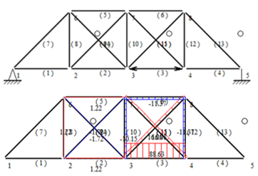
This paper presents a damage analysis of a statically indeterminate truss structure under ideal conditions. In light of the statically indeterminate truss's structural configuration and the stiffness of all its members, it is assumed that damage exists in two of the truss members and that the prior distribution of two members is known. The specific values are shown in Figure 1 and Table 1.
| |
Figure 1. Research objects truss. | |
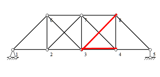
In Figure 1, the red color represents the damaged members, and the distance and height between the two nodes of the transverse truss are 15 metres. The distribution of damaged members before the implementation of the proposed solution is as follows:
The prior distribution of member 3-4 obeys the uniform distribution U(0.56,1.54).
The prior distribution of member 3-8 obeys the uniform distribution U(0.28,1.26).
Table 1. Stiffness of other members |
Member | 1-2 | 2-3 | 4-5 | 1-6 | 6-7 | 7-8 | 2-7 |
EA \( ({10^{5}}kN/m) \) | 1.4 | 1.33 | 1.4 | 1.54 | 1.47 | 1.47 | 1.25 |
Member | 8-5 | 2-6 | 3-6 | 3-7 | 4-8 | 4-7 | |
EA \( ({10^{5}}kN/m) \) | 1.54 | 1.26 | 1.12 | 1.12 | 1.26 | 1.05 |
In this study, the trusses were assumed to be linearly elastic, with a certain degree of measurement error. It was assumed that the modulus of elasticity E was constant and identical for all data set members presented in Table 1. Subsequently, each item in the table was divided by E to conduct the cross-sectional area sampling. The proposed methodology for modifying the loading points and monitoring the displacement points is constrained by the following parameters: the maximum load that can be applied at each node is limited to 100kN (either vertically or horizontally), and each node can be monitored for x- and y-direction displacements.
3.2. Research process
Specifically, the aforementioned process was achieved through the utilization of Opensees modelling and Excel to plot histograms in the following steps:
• A truss model is constructed, the value of the damaged stiffness of the target member is posited within the a priori distribution, and then the displacement values are output and recorded.
• A truss model with the same structural characteristics is created anew, selected at random from the prior distribution, and the randomly generated values are assigned to the stiffness of the member, thereby producing the corresponding displacement values.
• A comparison of the displacement values generated from the models constructed in the initial two steps is next, with particular attention paid to the error. Acceptance-rejection sampling should then be employed to determine whether the sampled data should be accepted, with the resulting stiffness outputted if so.
• A substantial number of repetitive samples must be performed in order to generate a collection of samples, thus obtaining the posterior distribution.
• The obtained posterior distribution was plotted as a histogram in Excel, and the mean value and standard deviation of the data should be calculated to observe the optimization situation.
• Steps 2 to 5 were repeated, with both the loading node and the monitoring displacement node undergoing alteration until the optimal posterior distribution was achieved.
• Once the optimal solution has been identified, the damaged member is updated according to the true displacement values calculated from the optimal solution. Subsequently, the results are compared with the true damage values in order to verify the conclusions drawn.
A discussion of the results will now be presented.
3.3. Preliminary study
The preliminary study was predominantly informed by the exhaustive method. The control variable method was employed to implement this process. This entailed fixing the loading node and changing the monitoring displacement node, as well as fixing the monitoring displacement node and changing the loading node. Finally, the corresponding histograms were plotted based on the data output from each scheme.
3.3.1. Influence of load magnitude
The first objective is to investigate the impact of load magnitude by modifying solely the load magnitude while maintaining the loading and monitoring scheme. Given that the impact of load magnitude on displacement is negligible under relative error, the absolute error is employed for execution.
|
Figure 2. Updating effects with different loads under absolute error |
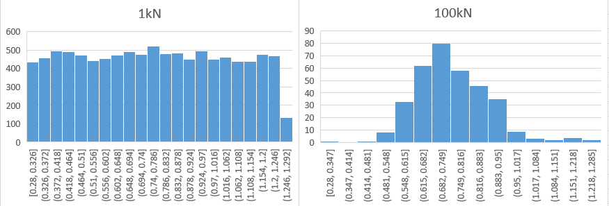
As illustrated in Figure 2, the member exhibits minor updating effects when the load is relatively low, due to the inability to produce more pronounced displacement. However, a pronounced updating effect is observed when the load reaches 100kN. It can be concluded that the greater the load, the more pronounced the updating effect. The following analysis will be applied using a load of 100kN. The damaged members 3-4 and 3-8 have been subjected to a considerable axial force, while the remaining members have experienced either a minimal or negligible axial force.
3.3.2. Stage of exhaustive enumeration of all node schemes
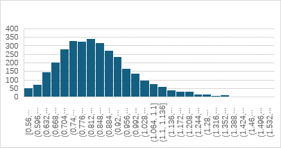
At this stage, it was first observed that the updating results were poor for both target members when loads were applied at the 2-node or the 6-node. Figure 3 illustrates one such case, wherein the vast majority of displacement nodes exhibit an insignificant distribution. Furthermore, the histograms generated when nodes 2 and 6 are employed as monitoring displacement node exhibit a similar pattern to those previously described. This indicates that the information provided by these two nodes is not deemed to be significant and will not be considered in subsequent analyses.
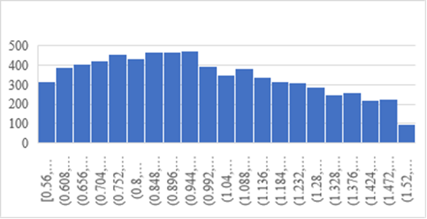
Figure 3. Histogram of the displacement of node 2 monitored with load acting on node 7
It was additionally determined that when monitoring the 4 node displacements, good updating effects on members 3-4 could be observed with loads acting on any of the nodes. Conversely, a significant updating effect on the 3-8 member was only discernible when monitoring the 8 node displacements. Figure 4 illustrates that even the 2-node loads, subject to poor updating as previously described, can be updated with reasonable accuracy when monitoring 4-node displacements. The findings indicate that monitoring displacement schemes exert a more pronounced influence on the updating effect than loading schemes.
| |
Figure 4. Histogram of 3-4 member with monitoring 4-node displacements and 2-node loading | |
Given the rather large sample size and the amount of redundant information obtained through the exhaustive method, only a few representative graphs have been selected for presentation. The following is a summary of the initial analysis:
• The greater the load, the more effective the updating.
• The update of nodes 2 and 6 is inadequate, and subsequent optimizations primarily focus on four other nodes.
• Monitoring displacement schemes exerts a more pronounced influence on the updating effect than loading schemes.
• It is not necessary to update both members simultaneously; their respective optimizations should be discussed separately, given the markedly disparate stress conditions under which they operate.
3.4. Deep optimization
Since the samples are judged acceptable or unacceptable by their deviation from the true displacement values, the effect of truss displacement is considered to be analyzed. Given that the displacement formula (4) is a sum formula, if there is a strong correlation between the displacement value and the damaged member, an effective updating effect can be obtained if the term representing the damaged member is larger than the other terms. The only thing that is relevant to the variation scheme in the equation is the axial force. It is therefore necessary to ensure that the value of \( {N_{p}}∙\bar{N} \) is large compared to the other members. That is, the axial force on the damaged member reaches its maximum value in both the actual loading case and the virtual force case. The former depends on the loading node, while the latter depends on the monitoring displacement node. The objective of the optimization is to identify a suitable loading node and monitoring displacement node, with the aim of ensuring that the axial force of members 3-4 and 3-8 is greater than that of the other members in both the real and virtual cases.
3.4.1. Optimization of loading schemes
In order to identify the optimal loading scheme for maximizing the axial forces in members 3-4 and 3-8, it is first necessary to consider the application of applying two opposite loads along the direction of the parallel member at both ends of the member. This approach can potentially subject the members to significant axial forces, thereby enhancing the scheme's effectiveness. Nevertheless, applying diagonal loads to diagonal brace 3-8 in practice is challenging, which has led to the continued use of the vertical loading scheme.
| |
Figure 5. 3-4 Member loading scheme and its axial force diagram | |
| |
Figure 6. 3-8 Member loading scheme and its axial force diagram | |
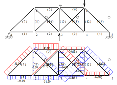
As illustrated in Figure 5 and Figure 6, the damaged members 3-4 and 3-8 have been subjected to a considerable axial force, while the remaining members have experienced either a minimal or negligible axial force.
3.4.2. Optimization of the monitoring node schemes
The preceding theory posits that the optimal monitoring displacement points are also situated at the two nodes which applied loads. Nevertheless, in order to minimize the cost, it is anticipated that only one monitoring node will be selected. Optimization aims to apply a load at a single node and identify the scheme that exhibits the highest axial force in the target member.
| |
Figure 7. Axial force diagram with horizontal rightward load applied at 4 node only. | |
| |
Figure 8. Axial force diagram with vertical upward load applied at 3 node only. | |
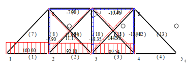
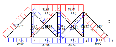
The final selection resulted in node 4 being designated as the monitoring displacement node for rods 3-4, while node 3 was designated as the monitoring displacement point for rods 3-8. The corresponding axial force diagrams are presented in Figure 7 and Figure 8.
3.4.3. Final optimization scheme
The final optimization scheme for the 3-4 member is as follows: in terms of the loading scheme, 100KN is loaded horizontally to the left at the 3 node and 100KN horizontally to the right at the 4 node. Regarding the monitoring node displacement scheme, the 4 node x- and y-direction displacements are monitored concurrently. For this analysis, it is assumed that the absolute error is 0.5mm and the measurement error is 0.5m standard deviation.
| |
Figure 9. Histogram of the final optimized scheme for member 3-4 | |
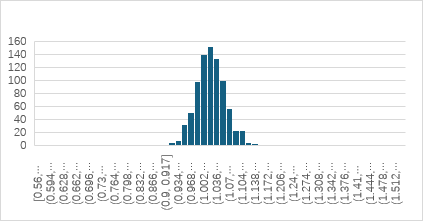
The true value of the displacement calculated by modelling is used as the update information: the displacement of 4 node in y and x direction is -0.007746m,0.013214 m, respectively. A histogram is drawn based on the sampled data, as shown in figure. 9. The Figure 9 illustrates that the parameter effectively converges to a concentrated region following a series of transition stages from a uniform initial distribution. The posterior distribution exhibits minimal dispersion, enhancing the optimization's effectiveness. The mean and standard deviation of the sampling data were calculated as 1.029542 and 0.038805, respectively. The true value of the damaged member was determined to be 1.00800, and the difference value between the mean value of the update result and the true value was found to be Δ=1.029542-1.00800=0.021542. This indicates that the updating effect is satisfactory.
The final optimization scheme for the 3-8 member is as follows: in terms of the loading scheme, 100KN is loaded vertically upward at the 3 node and 100KN vertically downward at load 8 node. In terms of the monitoring node displacement scheme, the 3 node x- and y-direction displacements are monitored concurrently. For this analysis, it is assumed that the absolute error is 0.5mm and the measurement error is 0.5m standard deviation. For the purposes of this analysis, it is assumed that the absolute error of the measurement error is 0.5mm and the standard deviation is 0.5m.
| |
Figure 10. Histogram of the final optimized scheme for member 3-8 | |
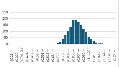
The true value of the displacement calculated by modelling is used as the update information: the displacement of node 3 in y and x direction is 0.022509m, -0.005883m respectively. A histogram is drawn based on the sampled data, as shown in Figure. 10. The figure illustrates that the parameter effectively converges to a concentrated region following a series of transition stages from a uniform initial distribution. The posterior distribution exhibits minimal dispersion, enhancing the optimization's effectiveness. The mean and standard deviation of the sampling data were calculated as 0.90361 and 0.074351, respectively. The true value of the damaged member was determined to be 0.87800, and the difference value between the mean value of the update result and the true value was found to be Δ=00.90361-00.87800=0.02561. This indicates that the updating effect is satisfactory.
The above two figures demonstrate the efficacy of the optimization direction proposed in this paper.
4. Conclusion
This paper presents an update of two of the damaged members of the statically indeterminate truss. In the event that the extent of damage to the members is known, the posterior distribution of the stiffness of the damaged members is updated continuously through sampling, thereby realizing an update that is very close to the true value. Concurrently, the optimal monitoring scheme for damage identification of truss members was identified through a process of continuously changing the loading and monitoring displacement node schemes, as well as the principle of virtual work. The following conclusions were then drawn:
1) The greater the magnitude of the load, the more pronounced the beneficial effect of the damaged member's updating. This is due to the fact that larger loads can result in more discernible displacement.
2) The direction of truss damage identification is to adjust the scheme to ensure the axial force of the target member is significantly greater than that of the other members.
3) Although this paper is primarily concerned with statically indeterminate trusses, this law can also be extended to determinate trusses and all trusses statically. The objective of the optimization scheme is to subject the diagonals to shear and the chords to bending moments or direct tension.
Nevertheless, there are some limitations in the methodology employed in this study. For instance, the displacement was not monitored in a single direction, and a step-by-step loading scheme was not attempted. These shortcomings may result in the optimization results not reaching an optimal state. It is proposed that future studies should consider the correlation or overlap between the information provided by the loading and displacement nodes schemes. The combination of two pieces of information that are highly correlated and contain a large amount of similar information will result in a weak boost, which may lead to inefficiency. Conversely, if the two pieces of information do not contain significant overlapping content, they can be considered complementary, which may result in more effective updates. Subsequently, the objective of the future truss optimization scheme will be to determine the most appropriate methodology for selecting the loading nodes and monitoring displacement nodes, to ensure that the information provided by these nodes is complementary.
References
[1]. Li X H 2009 A Bayesian Probabilistic Approach to Structural Parameter Identification and Application Institute of Engineering Mechanics, China Earthquake Administration
[2]. Zhong Z H, Niu J and Wang H 2012 China Civil Engineering Journal 45(08) pp 121-130
[3]. Feng X, Li G Q and Zhou J 2005 Earthquake Engineering and Engineering Vibration (02) pp 105-113
[4]. Shen J L 2015 Structural damage identification based on advanced Bayesian probabilistic inference sampling approach and application in truss structures Hefei University of Technology
[5]. Bernardo J M and Smith A F M 2002 Bayesian Theory (New York : John Wiley and Sons Inc)
[6]. Beck J L 1989 American Society of Civil Engineers
[7]. Beck J L and Katafygiotis L S 1991 Updating of a model and its uncertainties utilizing dynamic test data Proc. 1st Int. Conf. on Computational Stochastic Mechanics (Boston: Computational Mechanics Publications) pp 125–136
[8]. Beck J L and Katafygiotis L S 1998 Journal Of Engineering Mechanics 124(4) pp 455-461
[9]. Fishman G S 1996 Monte Carlo: Concepts, Algorithms, and Applications (Berlin: Springer)
[10]. Yuen K V 2010 Bayesian methods for structural dynamics and civil engineering (New York : John Wiley and Sons Inc)
[11]. Yuen K V and Katafygiotis L S 2005 Earthquake Engineering & Structural Dynamics 34(2) pp 167-187
[12]. Hastings W K 1970 Biometrika 57(1) pp 97-109
[13]. Zhou X Z, Lin J H, Hu Z W and Zheng J J 2020 Journal of Zhejiang University of Technology 48(02) pp 212-216
Cite this article
Song,P. (2024). Truss structural damage identification based on Bayesian probabilistic inference. Applied and Computational Engineering,91,11-20.
Data availability
The datasets used and/or analyzed during the current study will be available from the authors upon reasonable request.
Disclaimer/Publisher's Note
The statements, opinions and data contained in all publications are solely those of the individual author(s) and contributor(s) and not of EWA Publishing and/or the editor(s). EWA Publishing and/or the editor(s) disclaim responsibility for any injury to people or property resulting from any ideas, methods, instructions or products referred to in the content.
About volume
Volume title: Proceedings of the 2nd International Conference on Functional Materials and Civil Engineering
© 2024 by the author(s). Licensee EWA Publishing, Oxford, UK. This article is an open access article distributed under the terms and
conditions of the Creative Commons Attribution (CC BY) license. Authors who
publish this series agree to the following terms:
1. Authors retain copyright and grant the series right of first publication with the work simultaneously licensed under a Creative Commons
Attribution License that allows others to share the work with an acknowledgment of the work's authorship and initial publication in this
series.
2. Authors are able to enter into separate, additional contractual arrangements for the non-exclusive distribution of the series's published
version of the work (e.g., post it to an institutional repository or publish it in a book), with an acknowledgment of its initial
publication in this series.
3. Authors are permitted and encouraged to post their work online (e.g., in institutional repositories or on their website) prior to and
during the submission process, as it can lead to productive exchanges, as well as earlier and greater citation of published work (See
Open access policy for details).
References
[1]. Li X H 2009 A Bayesian Probabilistic Approach to Structural Parameter Identification and Application Institute of Engineering Mechanics, China Earthquake Administration
[2]. Zhong Z H, Niu J and Wang H 2012 China Civil Engineering Journal 45(08) pp 121-130
[3]. Feng X, Li G Q and Zhou J 2005 Earthquake Engineering and Engineering Vibration (02) pp 105-113
[4]. Shen J L 2015 Structural damage identification based on advanced Bayesian probabilistic inference sampling approach and application in truss structures Hefei University of Technology
[5]. Bernardo J M and Smith A F M 2002 Bayesian Theory (New York : John Wiley and Sons Inc)
[6]. Beck J L 1989 American Society of Civil Engineers
[7]. Beck J L and Katafygiotis L S 1991 Updating of a model and its uncertainties utilizing dynamic test data Proc. 1st Int. Conf. on Computational Stochastic Mechanics (Boston: Computational Mechanics Publications) pp 125–136
[8]. Beck J L and Katafygiotis L S 1998 Journal Of Engineering Mechanics 124(4) pp 455-461
[9]. Fishman G S 1996 Monte Carlo: Concepts, Algorithms, and Applications (Berlin: Springer)
[10]. Yuen K V 2010 Bayesian methods for structural dynamics and civil engineering (New York : John Wiley and Sons Inc)
[11]. Yuen K V and Katafygiotis L S 2005 Earthquake Engineering & Structural Dynamics 34(2) pp 167-187
[12]. Hastings W K 1970 Biometrika 57(1) pp 97-109
[13]. Zhou X Z, Lin J H, Hu Z W and Zheng J J 2020 Journal of Zhejiang University of Technology 48(02) pp 212-216