


1. Introduction
The topic of reaching the carbon peak has gained increasing attention from the scholarly community as well as the general public in recent years, and it has had a major impact on The Times' evolution. The use of new energy generation has gradually become the mainstream of the world. The utilization rate of wind power generation is increasing, and by the end of 2023, the total global wind power generation has reached 1,021GW, of which offshore wind power is 75GW and continues to rise. Analysis of wind resources, wind farm layout, wind turbine design, control technology, and wind farm siting are all included in wind energy technology. The wind turbine control system has grown in importance as a means of ensuring the wind energy conversion system's stability and effectiveness, and control technology is essential to the wind turbine's overall stable and effective functioning [1].
2. Analysis
2.1. Basic principle of offshore fan
Typically, an offshore wind farm has a specific quantity of wind turbines and transmission equipment.. Wind turbines convert wind energy into electricity, and transmission systems deliver electricity to substations. Wind turbine is a power generation device of wind farm. A single wind turbine includes blades, fans, tower and foundation parts. The working principle of the fan is the principle of aerodynamics [2]. The lift force generated by the pressure difference between the front and back sides of the blades is used to rotate the fan and pass through the gearbox to drive the wind turbine rotor, transforming wind energy into the rotor's kinetic energy in the generator, and finally transforming the rotor's kinetic energy into electrical energy output.
2.2. Wind energy theory
According to the expression of wind energy:
\( E=\frac{1}{2}ρ{Av^{3}}\ \ \ (1) \)
Where, V is the wind speed, ρ is the air density, and A is the swept area of the wind wheel.
It can be seen that the size of the wind energy and the airflow density is proportional to the cube of the swept area through the wind wheel and the airflow velocity. ρ and v are correlated with altitude, geomorphic conditions, geographical location and other factors.
2.3. Wind wheel theory
According to the Bates limit [3], the energy that the wind turbine absorbs from the surrounding air has a limit, and the power consumption part is the kinetic energy of rotation retained in the wake portion. The power reduction is mainly caused by energy conversion, and the specific value depends on the model of the wind turbine and generator used, so the wind energy utilization coefficient of the wind turbine in practical applications is Cp<0.593
2.4. Characteristic coefficient of the fan
Wind energy utilization coefficient Cp: the degree of energy that The wind energy efficiency coefficient expresses how much power a wind turbine can produce from the natural wind.
Blade tip speed ratio λ: In order to represent the state of the wind wheel under varying wind velocities, the ratio of the PI speed of the blade tip to the wind speed is measured, which is called the blade tip speed ratio.
Torque coefficient CT and thrust coefficient CT: In order to easily compare the torque and thrust generated by the wind turbine under the action of the air flow, the variable λ is generally made into a curve of torque and thrust.
2.5. Leaf element momentum theory
Leaf element momentum theory is composed of two parts, specifically, momentum theory and leaf element theory. The leaf element is divided into many micro segments along the wind turbine blade. It is assumed that the mutual flow on each blade element is independent, that is, the blade element can be regarded as a two-dimensional airfoil. In this case, the aerodynamic characteristics acting on each blade element can be integrated along the radial direction to obtain the aerodynamic characteristics of the entire wind turbine [4].
3. Control theory and model
3.1. Fan yaw control principle
Making sure the wind wheel is correctly aligned with the direction of the wind is the function of yaw in the wind system, the most basic component is the yaw bearing connecting the main frame and the tower barrel, the active yaw drive is usually used in the upwind wind turbine, sometimes also used in the downwind wind generator, it is equipped with a number of yaw motors, each of which is used to drive a tiny gear that is meshing with a large gear, which is attached to the yaw bearing. An active yaw system, which is frequently employed in downwind wind turbines, controls this process with a wind direction monitor installed on the wind turbine nacelle [5].
3.1.1. Adaptive control
Because the speed of the wind, wind turbine acceleration, and paddle angle have a nonlinear relationship, the dynamic performance of wind turbine depends on wind speed to a large extent. The controller is designed with the lowest sensitivity to these parameter changes so that it can adapt to system parameter changes. Systems with fluctuating characteristics, particularly those with rapid or broad fluctuations, can also benefit from these adaptive control approaches. The Adaptive management scheme ongoing measures the values of the system parameters and then changes the dynamic characteristics of the control system to ensure that the desired performance standards are always met.
3.1.2. Optimal control
Changes in the input signal balance variations in the system output in an optimal control system, which operates in the temporal domain. Optimal control is originally a multi-variable method, which makes it suitable for the control design of variable speed wind turbines. The control problem has been defined by optimal control theory. according to the performance metric, which is usually a result of the mistake between the control command and the actual response of the system, and then uses mature mathematical methods to determine the values of the design parameters, so that the value of the performance index is maximum or minimum. The optimal control algorithm usually needs to detect the state variables of the system or the state observer based on the machine model.
3.2. Power control of wind turbine
3.2.1. Generator model
The wind power producing the system's power management component generally includes: wind speed model, pneumatic model, generator part, gearbox part and frequency converter part.
The wind turbine studied in this paper is an asynchronous generator, whose output power varies according to the slip rate, and the slip rate is controlled by adjusting the frequency converter, so as to achieve variable speed constant frequency [6].
Coordinate transformation: Both the stator and three windings can be compared to the rotor of a three-phase asynchronous motor, and After coordinate transformation, the two-phase stationary coordinate system and the three-phase stationary coordinate system can be equivalent., and then the two-phase stationary coordinate system is equivalent to the rotating two-phase coordinate system with rotation speed \( {ω_{1}}=0 \) [7].
Mathematical model of asynchronous generator:
\( \begin{cases} \begin{array}{c} \frac{{d_{ω}}}{dt}=\frac{n_{p}^{2}{L_{m}}}{{J_{G}}Lr}({i_{sq}}{Ψ_{rd}}-{i_{sd}}{Ψ_{rq}})-\frac{{n_{p}}}{{J_{G}}}{T_{L}} \\ \frac{d{Ψ_{rd}}}{{d_{t}}}=-\frac{1}{{T_{r}}}{Ψ_{rd}}+({ω_{1}}-ω){Ψ_{rq}}+\frac{{L_{m}}}{{T_{r}}}{i_{sd}} \\ \begin{matrix}\frac{d{Ψ_{rq}}}{{d_{t}}}=-\frac{1}{{T_{r}}}{Ψ_{rq}}+({ω_{1}}-ω){Ψ_{rd}}+\frac{{L_{m}}}{{T_{r}}}{i_{sq}} \\ \begin{matrix}\frac{{di_{sd}}}{dt}=\frac{{L_{m}}}{σ{L_{r}}{L_{s}}{T_{r}}}{Ψ_{rd}}+\frac{{L_{m}}}{σ{L_{r}}{L_{s}}}{Ψ_{rq}}ω-\frac{{R_{s}}L_{r}^{2}+{R_{r}}L_{m}^{2}}{σ{L_{s}}L_{r}^{2}}{i_{sd}}+{ω_{1}}{i_{sq}}+\frac{{u_{sd}}}{σ{L_{s}}} \\ \frac{{di_{sq}}}{dt}=\frac{{L_{m}}}{σ{L_{r}}{L_{s}}{T_{r}}}{Ψ_{rq}}+\frac{{L_{m}}}{σ{L_{r}}{L_{s}}}{Ψ_{rd}}ω-\frac{{R_{s}}L_{r}^{2}+{R_{r}}L_{m}^{2}}{σ{L_{s}}L_{r}^{2}}{i_{sq}}+{ω_{1}}{i_{sd}}+\frac{{u_{sq}}}{σ{L_{s}}} \\ \end{matrix} \\ \end{matrix} \end{array} \end{cases}\ \ \ (2) \)
Where: \( {u_{sd}} \) , \( {u_{sq}} \) are the stator voltage at coordinate \( {d_{q}} \) , \( {i_{sd}} \) and \( {i_{sq}} \) are the stator current, \( {ω_{1}} \) is the rotation speed at coordinate \( {d_{q}} \) , \( ω \) is the asynchronous motor speed, \( {T_{L}} \) is the load torque, \( {R_{s}} \) is the stator winding resistance, \( {Ψ_{rd}} \) and \( {Ψ_{rq}} \) are the rotor flux, \( {L_{m}} \) is the mutual inductance between the stator and the rotor equivalent winding, \( {L_{s}} \) is the self-inductance of the stator equivalent two-phase winding. \( {L_{r}} \) is the self-inductance of the equivalent two-phase winding of the rotor, \( {n_{p}} \) is the pole number, \( {T_{r}} \) is the electromagnetic time constant of the rotor, \( {T_{r}}={L_{r}}/{R_{r}} \) is the equation of state, and \( {J_{G}} \) is the moment of inertia of the asynchronous motor unit.
3.2.2. Gearbox system
The simplified model of the gearbox system is shown in the figure. The wind turbine shaft and generator shaft are respectively installed on the left and right sides of the gear, and the tooth ratio is the speed ratio of the left and right sides of the gear [8]. The simulation model is simplified, ignoring the energy consumption in the transmission process of the actual operation of the gearbox.
Gearbox drive system dynamic model:
\( ({J_{rot}}+N_{gear}^{2}{J_{G}})\frac{{dw_{rot}}}{dt}={T_{at}}-{N_{gear}}{T_{G}}\ \ \ (3) \)
Where \( {w_{rot}} \) is the speed of the wind wheel, \( {J_{G}} \) is the moment of inertia of the generator, \( {J_{rot}} \) is the moment of inertia of the wind wheel, and \( {T_{G}} \) is the load torque.
3.2.3. Motor side inverter control model
Since the collector ring connects the motor side frequency converter with the winding asynchronous motor, the model of the motor side frequency converter in the dq coordinate system is:
\( \begin{cases} \begin{array}{c} {u_{rd}}={i_{rd}}{R_{r}}+σ{L_{r}}\frac{{di_{rd}}}{{d_{t}}}-{ω_{s}}(-\frac{{L_{m}}}{{ω_{1}}{L_{s}}}{U_{G}}+{ω_{s}}σ{L_{s}}{i_{rd}}) \\ {u_{rq}}={i_{rq}}{R_{r}}+σ{L_{r}}\frac{{di_{rq}}}{{d_{t}}}+σ{ω_{s}}{L_{r}}{i_{gd}}{i_{rq}} \end{array} \end{cases}\ \ \ (4) \)
Where, \( {U_{G}} \) is the power grid voltage.
If the load remains constant, the rotor current does not change. When the additional electromotive force is added to the circuit, the synthetic electromotive force of the rotor loop is reduced, so the rotor current and electromagnetic torque are correspondingly reduced, the load torque remains unchanged, and the motor speed is reduced.
The ideal electromagnetic power is:
\( {P_{em}}=s{P_{em}}+(1-s){P_{em}} \) (5)
Where, \( {P_{em}} \) is electromagnetic power; \( s{P_{em}} \) is the slip power.
3.3. Side wind and yaw error
Side wind \( {V_{0}} \) is perpendicular to the wheel shaft and perpendicular to the surface. It occurs because of yaw errors or sudden changes in wind direction. For the forward blade, it increases the tangential velocity. The speed of the tangential of the receding blade decreases. Note that tangential velocity is mostly affected by the cosine period disturbance that is responsible for yaw inaccuracy [9].
3.4. Yaw motion
In addition to causing the turning moment, yaw motion also affects the blade speed. If the position of the blade is vertical and there is a yaw rate, The blade will support the speed. \( q{d_{yaw}} \) due to yaw rotation ( \( {d_{yaw}} \) is the distance from the tower shaft to the center of the wind turbine). The speed will rise by \( rqsin(β) \) if the flapping angle causes the blade to tilt away from the axis of revolution. This impact is absent when the blade is in the horizontal position and is strongest when the blade is upright, up, or down.
3.5. Yaw stability
Any pure sinusoidal response results in a net torque around the yaw axis. The sinusoidal periodic response is affected by rotational motion, yaw error, wind shear and gravity. First of all, it should be pointed out that both vertical wind shear and gravity on the curved blade tend to cause the wind wheel to deviate from the wind in the same direction [10]. That means the wind wheel will be subjected to the side wind from the negative direction. The sideways wind caused by the yaw error attempts to turn the wind wheel back in the other direction.
3.6. Output power prediction
The output power of wind turbines varies with the wind speed, and each wind turbine has its own unique power curve. This curve can be used to predict power generation without taking into account the specific technicalities of other parts. The power output at the hub height as a function of wind speed is displayed on the power curve.
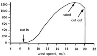
Figure 1. Classical curvature curve of wind turbine
3.7. Turbine power control: stall, variable pitch or pneumatic surface
At high wind speeds, stall control takes advantage of aerodynamic lift reduction at high angles of attack to reduce torque. For the stall to work, the rotor speed must be independently controlled. The stall-controlled wind turbine blades are fastened to the hub to form a simple connection. However, stall control is characterized by a relatively large wind speed to achieve maximum power. Stall-controlled wind turbines always use a separate braking system to ensure that the fan can be shut down when various conditions occur.
The blade of a variable blade wind turbine can rotate around its long axis and change its paddle Angle. Changing the paddle Angle also changes the Angle of attack relative to the wind and the torque generated. However, the wheels become more complex and need to be equipped with variable pitch bearings. In addition, a variable pitch execution system must be used.
Yaw control makes the wind wheel deviate from the wind direction to reduce the power, and the wheel hub must be able to withstand the rotating load caused by the yaw movement, but its structure is relatively simple.
4. Simulation analysis
In order to verify the control strategy proposed in this paper, a simulation model is built in Matlab/Simulink, and the rated power of the wind turbine is 1.8MW. Figure 1 shows the real wind speed during a certain period of time.
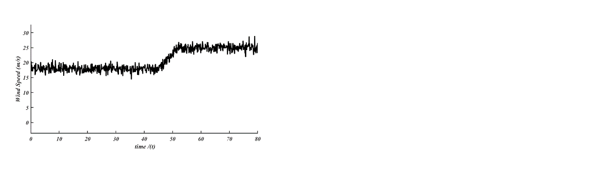
Figure 2. Real wind speed during a certain period of time
Figure 3.(a) shows the speed waveform of the fan under different wind speeds. In the figure, waveform A is the speed waveform under maximum power tracking control method, and waveform B is the speed waveform under wide speed operation control. Figure 3. (b) is the steering Angle waveform, and the waveform in the figure is the steering Angle waveform under the tracking control approach with greatest power; Figure 3.(c) is the output power waveform of the wind turbine, waveform A is the power waveform under the maximum power tracking control method, waveform B is the power waveform under the wide speed operation control. Figure 4. shows the working state of the fan at different wind speeds.
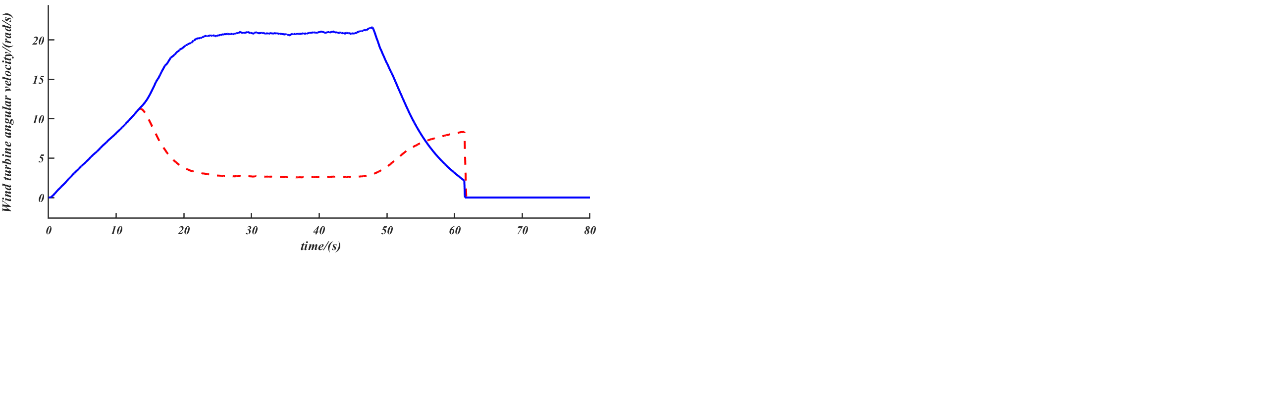
(a) Fan speed waveform at different wind speeds
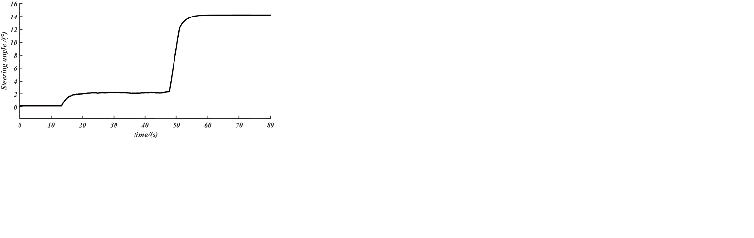
(b) Turning Angle waveform
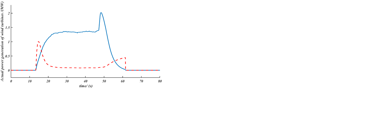
(c) Wind turbine output power waveform
Figure3. Wave form
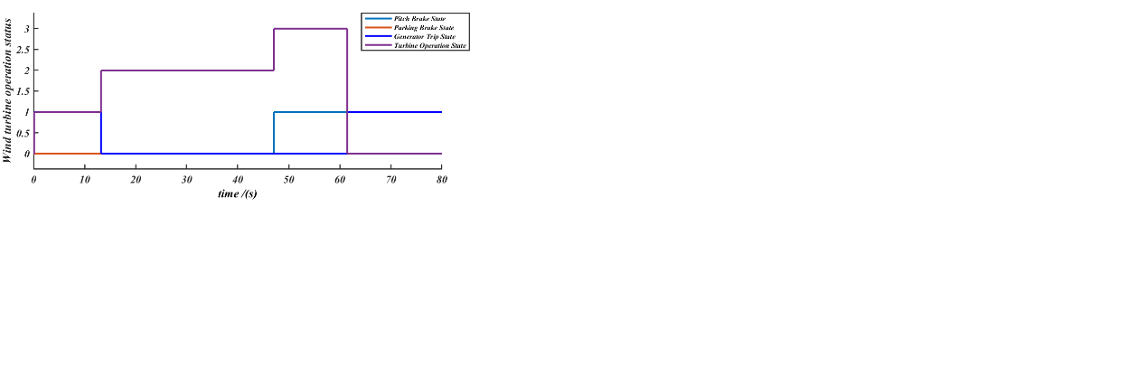
Figure 4. Fan working state
It can be seen from Figure 3.and Figure 4. that, compared with no steering Angle control, under the steering Angle control of maximum power point tracking, the steering Angle adjustment is gentle and the generating power is higher, which is due to the coordinated control of steering Angle and generator speed under this method. Between the cut wind speed and cut wind speed, the control of the maximum power point tracking steering Angle ensures that the fan is automatically aligned to the wind direction, minimizes wind turbine deterioration and keeps efficiency at its highest level across a broad range of wind speeds to maximize wind energy harvesting.
5. Conclusion
An adaptive control strategy of steering angle-speed coordination based on optimal control is proposed for offshore wind turbines. This strategy does not rely on the mathematical model of the offshore fan, and effectively avoids the bad influence of modeling errors and unmodeled dynamics on the control. By improving the adaptive control method of optimal control, the multi-input and multi-output controller is designed to smooth the output power, reduce the steering Angle regulation frequency, and relieve the operating pressure of the steering mechanism. Finally, based on Matlab/Simulink simulation, a 1.8MW fan is simulated under the actual wind conditions. The effectiveness of improving the adaptive control method by integrated iterative learning control is verified by comparison. The design of steering Angle - speed coordinated control strategy controller has better performance of power regulation.
The actual fan operation is more complex and more factors need to be considered. Therefore, there are still many aspects to be further studied, and the follow-up work can be improved from the following aspects: In the design of the controller for the control range below the rated wind speed, only the full power output of the fan is considered, and the lower limit power output of the rated wind speed is not considered. Further research on the fan power limited control strategy is needed.
In the design of the controller, this paper only pays attention to the fluctuation of power, the change of speed and steering Angle, and does not consider the load of the mechanical parts of the fan and the fatigue load of the transmission system tower. In the actual operation of the fan, the influence of all aspects should be considered comprehensively, and the overall optimal control objective should be established to achieve the overall optimal control of speed, power, mechanical load, etc.
The output power fluctuations generated during the operation of wind turbines can also be suppressed by energy storage devices such as wind turbines and batteries, and the energy storage system can also be applied to the frequency regulation of wind power systems and the compensation of active power, which will also be an aspect worth studying in the future.
References
[1]. Pan Xueping,Guo Jinpeng,Sun Xiaorong,etc.Frequency domain equivalent modeling method for frequency response characteristics of doubly-fed wind farms[J/OL]. Power grid technology,1-13[2024-07-04].https://doi.org/10.13335/j.1000-3673.pst.2024.0248.pp.1-9
[2]. Cai Yunxiu.Working principle and aerodynamic theoretical calculation of wind turbine[J].Scientific and technological information, 2012, (17):103-104+167. pp.104-105
[3]. Jiang Haibo,Cao Shuliang,Yang Ping.The power limits of horizontal axis wind turbines[J].Journal of Mechanical Engineering,2011,47(10):113-118.pp.113-114
[4]. Wang Qi. Optimization design of wind turbine blade shape based on multi-island genetic algorithm and momentum leaf element theory[J].Mechanical design and manufacturing engineering,2024,53(06):29-33.pp.29-30
[5]. Liu Yang. Analysis of the influence of improving wind measurement accuracy of wind vane on power generation [J]. Electric power survey and design 2018, (06):73-76.DOI:10.13500/j.cnki.11-4908/tk.2018.06.015.PP.73-76
[6]. Gao Fuwei. Research on maximum wind energy tracking control for variable speed constant frequency wind power system[J].Electronic fabrication, 2022, 30(02):90-92.DOI:10.16589/j.cnki.cn11-3571/tn.2022.02.024.pp.90-92
[7]. Li Jinchun. Research on real-time model predictive control for three-phase induction motor[D].Dalian University of Technology,2014.pp.29-40
[8]. Guo Guanghua, Chen Xuan, Guan Yingchun, etc. Design of vibration signal acquisition system for fan gear box[J].Electrical technology, 2023, (08):62-65.DOI:10.19768/j.cnki.dgjs.2023.08.016.pp.62-65
[9]. Hu Qiankun, Guo Peng, Dong Ketao, etc.Research on static yaw error diagnosis method of wind turbine based on distribution hypothesis testing[J].Electric power science and Engineering, 2024, 40(03):52-60.pp.53-54
[10]. Cheng Lifeng. Research on error and control strategy of wind turbine yaw system[D]. North China Electric Power University (Beijing),2017.PP.41-43
Cite this article
Wu,H. (2024). Adding Yaw System to Improve Wind Energy Utilization of Offshore Wind Turbines. Applied and Computational Engineering,91,46-53.
Data availability
The datasets used and/or analyzed during the current study will be available from the authors upon reasonable request.
Disclaimer/Publisher's Note
The statements, opinions and data contained in all publications are solely those of the individual author(s) and contributor(s) and not of EWA Publishing and/or the editor(s). EWA Publishing and/or the editor(s) disclaim responsibility for any injury to people or property resulting from any ideas, methods, instructions or products referred to in the content.
About volume
Volume title: Proceedings of the 2nd International Conference on Functional Materials and Civil Engineering
© 2024 by the author(s). Licensee EWA Publishing, Oxford, UK. This article is an open access article distributed under the terms and
conditions of the Creative Commons Attribution (CC BY) license. Authors who
publish this series agree to the following terms:
1. Authors retain copyright and grant the series right of first publication with the work simultaneously licensed under a Creative Commons
Attribution License that allows others to share the work with an acknowledgment of the work's authorship and initial publication in this
series.
2. Authors are able to enter into separate, additional contractual arrangements for the non-exclusive distribution of the series's published
version of the work (e.g., post it to an institutional repository or publish it in a book), with an acknowledgment of its initial
publication in this series.
3. Authors are permitted and encouraged to post their work online (e.g., in institutional repositories or on their website) prior to and
during the submission process, as it can lead to productive exchanges, as well as earlier and greater citation of published work (See
Open access policy for details).
References
[1]. Pan Xueping,Guo Jinpeng,Sun Xiaorong,etc.Frequency domain equivalent modeling method for frequency response characteristics of doubly-fed wind farms[J/OL]. Power grid technology,1-13[2024-07-04].https://doi.org/10.13335/j.1000-3673.pst.2024.0248.pp.1-9
[2]. Cai Yunxiu.Working principle and aerodynamic theoretical calculation of wind turbine[J].Scientific and technological information, 2012, (17):103-104+167. pp.104-105
[3]. Jiang Haibo,Cao Shuliang,Yang Ping.The power limits of horizontal axis wind turbines[J].Journal of Mechanical Engineering,2011,47(10):113-118.pp.113-114
[4]. Wang Qi. Optimization design of wind turbine blade shape based on multi-island genetic algorithm and momentum leaf element theory[J].Mechanical design and manufacturing engineering,2024,53(06):29-33.pp.29-30
[5]. Liu Yang. Analysis of the influence of improving wind measurement accuracy of wind vane on power generation [J]. Electric power survey and design 2018, (06):73-76.DOI:10.13500/j.cnki.11-4908/tk.2018.06.015.PP.73-76
[6]. Gao Fuwei. Research on maximum wind energy tracking control for variable speed constant frequency wind power system[J].Electronic fabrication, 2022, 30(02):90-92.DOI:10.16589/j.cnki.cn11-3571/tn.2022.02.024.pp.90-92
[7]. Li Jinchun. Research on real-time model predictive control for three-phase induction motor[D].Dalian University of Technology,2014.pp.29-40
[8]. Guo Guanghua, Chen Xuan, Guan Yingchun, etc. Design of vibration signal acquisition system for fan gear box[J].Electrical technology, 2023, (08):62-65.DOI:10.19768/j.cnki.dgjs.2023.08.016.pp.62-65
[9]. Hu Qiankun, Guo Peng, Dong Ketao, etc.Research on static yaw error diagnosis method of wind turbine based on distribution hypothesis testing[J].Electric power science and Engineering, 2024, 40(03):52-60.pp.53-54
[10]. Cheng Lifeng. Research on error and control strategy of wind turbine yaw system[D]. North China Electric Power University (Beijing),2017.PP.41-43