


1. Introduction
The canard wings are a pair of small wings in front of the main wings on both sides of the aircraft cockpit, it is similar to placing the horizontal tails that are usually located on the two sides of the engine at the rear of the fuselage in a conventional layout, at the front. In the current canard wings research context, there are only several studies that discuss canard wings alone or compare horizontal tails with them, most of them are related to the combination with other layouts. This paper first analyzes the working principles of the canard wings, including the fundamentals of the canard wings and the realization of the effective canard wings, then this paper analyzes the influence of the deflection angle of the wing of the canard layout aircraft on its own lift and the effect of the pitching angle formed by the deflection of the canard wings in three circumstances. On this basis, this paper discusses the aerodynamic advantages and effects of canard wings on aircraft, and by comparing the literature related to another existence that is similar to canard wings on aircraft - the horizontal tails, it is concluded that the lifting effect of the canard wings is better than the horizontal tails. This paper can provide some reference value for scholars who study aircraft aerodynamics as well as those who study canard wings or horizontal tails.
2. Working principle of canard wings
2.1. The fundamentals of canards and the realization of effective canards
The center of gravity and aerodynamic focus of the aircraft are both located between the canard and the main wing, while the canard is a pair of small wings placed in front of the main wing. It provides positive lift to balance the aerodynamic center of gravity while the aircraft is in flight [1]. As the speed and pitching angle of the aircraft change, the aerodynamic centre moves backwards. The aerodynamic centre of an aircraft shifts backward significantly when it is traveling at supersonic speed, and as a result, the nose-down moment will considerably increase as well. Any airflow passing over the wing will be pulled out into a vortex. As shown in Figure 1, the vortex had been pulled out by the canard and strake wings of a Su-30sm, when it was in a circulating flight state. The vortices generated by the canard will affect the generation of vortices on the main wing surface due to downwash, resulting in a reduction in lift. When the distance between the canard and the main wing is far, the vortices of the canard are almost exhausted when it reaches the main wing, and the main wing is attenuated by the disturbance from the canard again [2]. When the distance between the canard and the main wing is shortened, a similar leading edge slit wing will be formed, the effective chord length and lift of the wing will be increased equivalently, and a high-pressure zone will be generated at the leading edge of the main wing; then the interference between the canard vortices and the main wing vortices will be beneficial, the lift coefficient and lift-to-drag ratio will be improved, and the stall angle of attack will also increase, which is known as the close coupling [1-2].
The canard location should be placed at a height that is at least not lower than the height of the main wing, because in that case the vorteices of the canard will not interfere with the vorteices on the main wing, and will be rapidly exhausted during transmission. Only when the height is greater than or equal to this position will the canard make a fierce downwash effect on the main wing, thus reducing the effective angle of attack and increasing the induced drag and lift simultaneously [2].
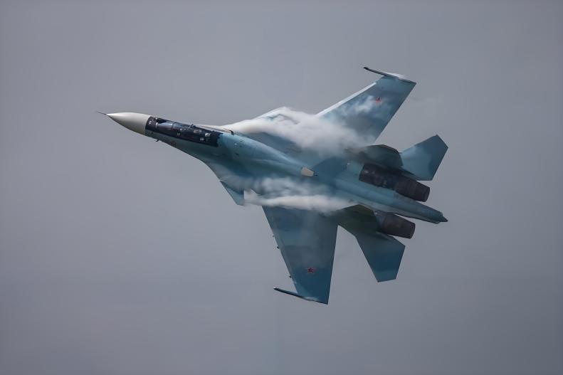
Figure 1. Su-30SM in a circulating flight state.
2.2. The influence of the wing deflection angle on lift of the canard aircraft
Angle of attack(AOA), as the name implies, is the angle formed by the chord of the aircraft wing and the laminar flow passing through it. From the above analysis, it can be seen that the canard will generate vortices, so the vortices will manifest as two types of disturbances under the two ranges of attack angle of the aircraft deflection separately. When the aircraft is in a small to medium AOA, the lost main wing lift is compensated by the canard lift, and its overall lift will not be affected. Because the vortex pulled out by the canard will produce a downwash effect, thereby restricting the formation of the main wing vortex, and through calculation it can be concluded that the generation of the leading edge vortex on the main wing will be disturbed; at the same time, adverse separation vortices will also form on the lower wing surface, but the lift loss in this part will be compensated by the lift generated by the canard [1]. Therefore, there is almost no unfavorable impact on the overall lift situation in the range of small and medium angles of attack.
When a canard aircraft at a large AOA range flight, or when the AOA of its canard increases, the effective AOA of the main wing(The angle between the velocity line synthesised by the disturbance and the chord line on the wing or the axis line on the fuselage)will decrease, the induced drag will increase, and the lift will increase significantly, but the lift-to-drag ratio will decrease; this is because the canard will still produce a downwash effect on the main wing in this case, which is similar to the small and medium AOA disturbances above [1-2]. But more importantly, the low-pressure vortex pulled out by the canard will compel the leading edge separation vortex on the main wing to form a stronger leading edge concentrated vortex so that the flow field is changed, which is the reason why the lift of the canard aircraft is increased. [1]. For example, at a large angle of attack of 20°, the pressure on the upper surface of the main wing increases because the vortex of the main wing is destroyed by the downwash of the canard, and the vortex lift is reduced [1]. However, since the pressure on the upper wing surface increases, the corresponding vortex lift of the canard also increases accordingly, so overall the lift generated by vortex does not change too much.
2.3. The effects of canard deflecting pitching angles in three cases
The nose-up moment is the ratio of the positive pitching moment coefficient Cm to the angle of attack Incidence ɑ, while the nose-down moment is a negative ratio, and the pitching moment balance Cm equals 0. Figure 2. shows how the three static stability of the aircraft in the longitudinal directions varies with changes in the angle of attack ɑ and the pitch moment coefficient Cm.
2.3.1. Static stability. For the static stability curve, shown in Figure 2, the slope is negative. When Cm is 0 , the angle of attack ɑₑ is the pitching moment equilibrium, on that occasion aircraft will neither nose down nor up; when the pitching moment coefficient decreases as the angle of attack ɑ increases, the aircraft is in a state of nose-down moment. The aircraft then has a tendency to return to the ɑₑ pitching moment equilibrium [3]. For a statically stable aircraft with a positive canard deflection, the curve Cm-ɑ will translate upward in the coordinate system of Figure 2, and the angle of attack at its ɑₑ pitching moment equilibrium will increase as well [3]. The new pitching moment balance of the angle of attack is ɑₑ+ɑ.
2.3.2. Neutral static stability. This neutral static stability curve is shown in Figure 2 as a horizontal straight line with the same slope as the x-axis of the angle of attack ɑ which is 0; regardless of how the angle of attack ɑ increases, it is still in a state of pitch moment balance, so the aircraft will produce neither nose-down nor nose-up moment. For a neutral statically stable canard aircraft, a positive upward deflection of the canard will cause the curve to translate upwards and parallel to the x-axis, so that in this case, the aircraft is still in a nose-up moment at the new angle of attack; therefore, in order to avoid a stall, the canard only can be straightened to a deflection angle of 0° at the corresponding angle of attack, so that the aircraft can re-achieve pitching moment equilibrium at the new angle of attack [3]. At that time, Cm equals 0, and the new pitching moment balance of the angle of attack is also ɑₑ+ɑ.
2.3.3. Static instability. Figure 2 shows that for this graph, the slope of the static instability curve is positive, showing a gradually improving trend. When the angle of attack Incidence ɑ increases, the pitching moment increases at the same time, because Cm also increases, so the aircraft will present a state of continuous nose-up; the nose-up moment simultaneously continues to increase, causing the aircraft to stall [3]. For a statically unstable canard aircraft, the canards do not actually need to be deflected significantly; a slight deflection of the canard will result in the aircraft continuously raising its head [3]. At this moment, the canard will deflect negatively downward, and this curve will translate downward in the coordinate system, allowing the canard aircraft to re-balance the pitching moment at the new angle of attack. ɑₑ+ɑ is likewise the new pitching moment equilibrium angle of attack, while Cm is naught.
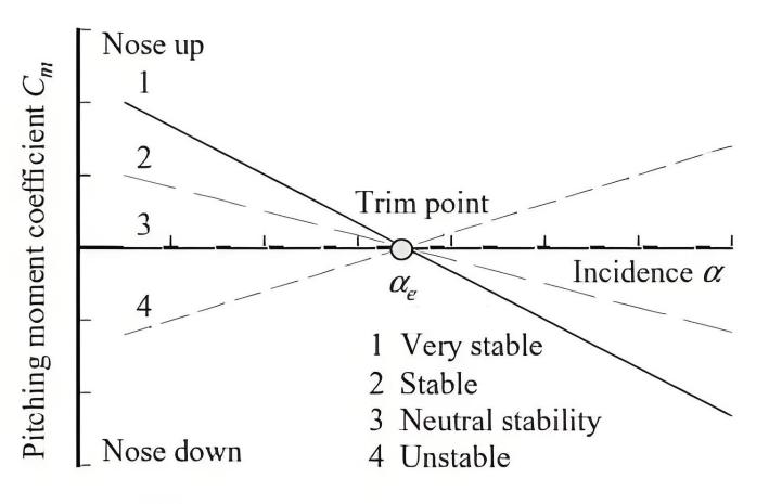
Figure 2. The linear equation graph of the degree of longitudinal static stability.
2.4. Analysis of effects on airframe stealth
RCS (Radar Cross Section) is a physical quantity that is the intensity of the echo received after the electromagnetic wave emitted by the radar is reflected by the target object [4]. The impact of canard on the overall RCS must be analyzed from the following two aspects: Supersonic cruise and a certain flight attitude including take off, landing, close combat or perform large maneuvers. Regarding the first aspect, when the aircraft is in a cruising state, the canard of an aircraft with canards will usually only deflect slightly and maintain a negative deflection angle, and the canard will not deflect positively [5]. Therefore, the frontal RCS of a canard aircraft will not be negatively affected when it is exposed to radar waves. As for the second aspect, the canard sometimes needs to be deflected significantly to perform certain special maneuvers, which will further damage the RCS of the entire fuselage and increase its RCS signature on the radar [5].
3. The aerodynamic advantages and effects of canards on aircraft
The advantages of aircraft using canard layouts are as follows: First, the aircraft has excellent nose-down control and recovery capabilities, especially at large angles of attack [1,6]. Second, in terms of vector thrust, when the direction of the canard balancing moment is the same as the direction of the vector thrust, they are superposed to form a resultant force. Third, the size and volume of the canard can be reduced, because the pitching angle control of the canard aircraft does not necessarily rely solely on the canard, but can also be assisted by the ailerons at the trailing edge of the main wing [1]. Fourth, when the canard aircraft accelerating in supersonic flight, the distance that the aerodynamic center moves backward to the aircraft fuselage is shortened, makes it easier to balance the moment in the supersonic flight, the canard is positively deflected simultaneously, and the balancing resistance of the canard aircraft is significantly reduced; The positive lift is generated by the canard trim moment, and the vortex lift generated by the changes in speed and angle of attack is derived from the favorable interference of the vortex coupling between the canard and the main wing, so the overall lift-drag ratio is expanded [1,6]. Finally, as to the advantages of canard deflection, canard aircraft experience an increase in lift when positive deflection occurs; as for negative deflection, it will be helpful to correct the aircraft from dangerous situations (such as stall or spin).
4. Comparison between the canards and horizontal tails
Regarding the aerodynamic layout of the two currently mainstream fighter jets, their advantages will also be compared next. According to Figure 3, the schematic diagram of lift for conventional and canard layout aircraft represents that the horizontal tails provide negative lifts, while the canards provide positive lifts. Therefore, it is usually simply considered that the canard wings are just the horizontal tails placed in front of the main wings, but this tacitly acknowledges that their respective contributions to the aircraft are concurrent. Through all the previous analyses of canards, its advantages are not only just the augment in the lift of the main wing vortex in the close coupling but also in its nose-down control ability, lift-to-drag ratio under supersonic endurance, vector thrust superposition and small canard surface. Compared with the conventional layout where the horizontal tail is placed at the rear, the canard is installed in front of the main wing, which is like installing a huge horn headlight and is easily noticed in dark and open areas. This is because, for the movable canard, the gap caused by the movement between it and the fuselage is directly exposed to the radar detection in front of the aircraft, increasing the possibility that the RCS characteristics of the fuselage are detected simultaneously [5]. But for the horizontal tail, which is located behind the main wings, the main wing blocks approximately most of the gaps that are prone to exposure risks when the horizontal tail moves, which greatly reduces the possibility of being detected by radar from the front. Therefore, conventional layout aircraft are ahead of canard layout aircraft in stealth.
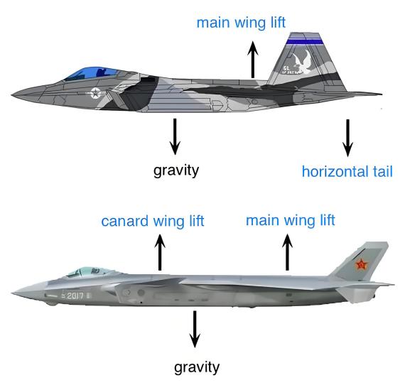
Figure 3. Schematic diagram of lift for conventional and canard layout aircraft
5. Conclusion
This paper mainly discusses the principle of effective lift increase of canards, using its aerodynamic advantages as well as the effect and influence of canard deflection angle on the aircraft under different conditions, and compares it with a horizontal tail. To sum up, there is no doubt that canards have an aerodynamic lift effect on an aircraft. Canards can only be effectively coupled when they are close to the main wing and longitudinally higher than or equal to the height of the main wings. Although the canard affects the lift of the main wing to a certain extent, it can also serve as a substitute and supply more lifts. In terms of stealth performance RCS compared with the horizontal tail, is like a tractor, large and loud, easier to be detected on the radar. This paper could add specific data and calculations for analysis and comparison in three aspects: the influence of the wing deflection angle of the canard aircraft on its own lift, the analysis of the effect of the fuselage's stealth, and the comparison between the canards and the horizontal tails. Future research could focus more on how aircraft can truly overcome gravity and implement anti-gravity technology.
References
[1]. Ma Baofeng, Liu Peiqing, Deng Xueying. Advances in aerodynamic research on close-coupled canard configuration[J]. Acta Aerodynamica Sinica, 2003(03):320-329.
[2]. Li Yulong, Yang Wei, Yang Zhigang. Numerical study of canard layout ground effect wing [J]. Aeronautical Computing Technology, 2010, 40(04): 27-30+34.
[3]. Fang Xiangduoduojigai. Why does the J-20's canard deflect in the opposite direction. 2022,12.www.bilibili.com/video/BV1cW4y1T768/?spm_id_from=333.788&vd_source=0310bce15ba005d6fac5e6050a08ef46
[4]. Jia Jianwei, Wang Cong, Zhang Yu, et al. Calculation of radar scattering cross section of aircraft coated with dielectric coatings[C]//Microwave Branch of China Electronics Society, Key Laboratory of Antenna and Microwave Technology. Proceedings of the 2016 National Conference on Military Microwave, Terahertz and Electromagnetic Compatibility Technology. 2016:3.
[5]. Guo Zhanzhi, Chen Yingwen, Ma Lianfeng. Research on the influence of radar scattering cross section of canard wings [J]. Acta Aeronautica Sinica, 2020, 41(06): 266-276.
[6]. Zhang Jigao. Aerodynamic layout division of fighter jets[J]. Acta Aerodynamica Sinica, 2009, 27(05): 616-622.
Cite this article
Lai,W. (2024). The working principles of canard wings and its aerodynamic advantages and effects on aircraft. Applied and Computational Engineering,91,83-88.
Data availability
The datasets used and/or analyzed during the current study will be available from the authors upon reasonable request.
Disclaimer/Publisher's Note
The statements, opinions and data contained in all publications are solely those of the individual author(s) and contributor(s) and not of EWA Publishing and/or the editor(s). EWA Publishing and/or the editor(s) disclaim responsibility for any injury to people or property resulting from any ideas, methods, instructions or products referred to in the content.
About volume
Volume title: Proceedings of the 2nd International Conference on Functional Materials and Civil Engineering
© 2024 by the author(s). Licensee EWA Publishing, Oxford, UK. This article is an open access article distributed under the terms and
conditions of the Creative Commons Attribution (CC BY) license. Authors who
publish this series agree to the following terms:
1. Authors retain copyright and grant the series right of first publication with the work simultaneously licensed under a Creative Commons
Attribution License that allows others to share the work with an acknowledgment of the work's authorship and initial publication in this
series.
2. Authors are able to enter into separate, additional contractual arrangements for the non-exclusive distribution of the series's published
version of the work (e.g., post it to an institutional repository or publish it in a book), with an acknowledgment of its initial
publication in this series.
3. Authors are permitted and encouraged to post their work online (e.g., in institutional repositories or on their website) prior to and
during the submission process, as it can lead to productive exchanges, as well as earlier and greater citation of published work (See
Open access policy for details).
References
[1]. Ma Baofeng, Liu Peiqing, Deng Xueying. Advances in aerodynamic research on close-coupled canard configuration[J]. Acta Aerodynamica Sinica, 2003(03):320-329.
[2]. Li Yulong, Yang Wei, Yang Zhigang. Numerical study of canard layout ground effect wing [J]. Aeronautical Computing Technology, 2010, 40(04): 27-30+34.
[3]. Fang Xiangduoduojigai. Why does the J-20's canard deflect in the opposite direction. 2022,12.www.bilibili.com/video/BV1cW4y1T768/?spm_id_from=333.788&vd_source=0310bce15ba005d6fac5e6050a08ef46
[4]. Jia Jianwei, Wang Cong, Zhang Yu, et al. Calculation of radar scattering cross section of aircraft coated with dielectric coatings[C]//Microwave Branch of China Electronics Society, Key Laboratory of Antenna and Microwave Technology. Proceedings of the 2016 National Conference on Military Microwave, Terahertz and Electromagnetic Compatibility Technology. 2016:3.
[5]. Guo Zhanzhi, Chen Yingwen, Ma Lianfeng. Research on the influence of radar scattering cross section of canard wings [J]. Acta Aeronautica Sinica, 2020, 41(06): 266-276.
[6]. Zhang Jigao. Aerodynamic layout division of fighter jets[J]. Acta Aerodynamica Sinica, 2009, 27(05): 616-622.