


1. Introduction
As the technology develops, plastic waste, which is also known as the “white pollution”, has become an increasingly serious environmental issue [1]. Many cities’ appearance is severely devastated by the ’white line’ alongside highways and railways, ’natural land- fill’ in lakes and ponds, white garbage in senetic spots and suburb areas [2]. According to Rochman, Browne et al., more than 280 million tonnes of plastic is produced around the world annually [3], but less than half is considered landfilled or recycled. Plastic debris that is not carefully dealt with can harm wildlife by emitting or absorbing toxic pollutants [3]. To make things worse, abandoned plastic products may end up in the ocean if tossed into rivers or carried away by a flood, causing injury, trapping, drowning, or even destroying an ecosystem. For instance, seabirds and sea turtles have been observerd to ingest plastic waste as early as 1960s [4] . It is of urgent need that plastic waste be located and carefully collected before it runs into water systems.
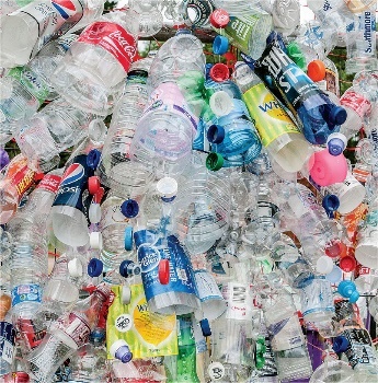
Figure 1. Plastic waste.Credit: P. Tomlins
Scientists and goverments have put much effort in solving this issue. By December 2021, goverments of more than 90 countries and regions have established policies encouraging people to limit the use of disposible plastic items and to recycle plastic waste [3,5]. The strategy are usually called the “3Rs”: reduce, reuse and recycle. Scientists have also developed biodegradable plastic to reduce the harm of randomly disposed plastic waste [1]. But the outcome is far from a successful stop of plastic pollution [6]. One of these methods’ limitations is that they can only prevent further pollution but not monitor or reduce current pollution.
Currently, gathering and monitoring white pollution still requires massive manual work. Human sight and mobility are limited when it comes to locating plastic waste in remote areas or in mountains. Unmanned Aerial Vehicles, or drones, shows promising potential for that job.
On the same time, detection of small objects on the drones is a challenging topic. Their indistinguishable features, low resolution and complicated background make it difficult for common models to detect and locate the objects. Lack of enough information provided in a image also makes it more likely to mistake one object for other items [7].
This paper proposes a set of software that can utilize drones and computer vision (CV) technology to help organizations and governments to locate and monitor plastic waste situations, featuring:
• An UAV system, specially designed for detection of plastic waste in vast and expansive areas.
• Object detection algorithm based on artificial intelligence that discriminates plastic waste.
• Localizing algorithm that can locate plastic waste in expansive areas.
This system is capable of effectively guiding cleaning work, thereby improving cleaning efficiency and reducing environmental impact.
2. Related works
2.1. UAVs
The Unmanned Aerial Vehicle (UAV) refers to an automatic vehicle operated by man, with the characteristics of low price, flexible mobility. UAV has an increasing degree of integration and more abundant functions, playing an increasingly important role in many fields. In the military field, UAV can complete intelligence reconnaissance and precision target strike tasks at low cost, which has important strategic significance for the country’s air control. In the civil field, uav has also made great progress, such as agricultural irrigation, vehicle monitoring, electric power inspection, film and television shooting, geographic mapping, emergency rescue and [8-10]. In complex environments where humans are difficult to move, sending drones to search for targets is a fairly convenient way. In our study, UAV was adopted as a carrier of technology to exert its advantages such as flexibility and convenience.
2.2. Small target detection
Traditional target detection often uses a sliding window to identify regions of interest, followed by Scale Invariant Feature Transform (SIFT) for feature extraction and classification regression [11]. However, with advancements in deep learning, significant progress has been made in deep neural network-based target detection. Current methods are categorized into Anchor-based, Anchor-free, and Transformer-based detection. Anchor-based detection, including two-stage and one-stage processes like YOLO [12], involves generating candidate regions using predefined anchors for classification and regression. Single-stage methods like SSD [13] use a pyramid structure for prediction across different scales. Anchor-free methods, which do not require predefined anchors, offer a simpler and faster alternative, performing well with small and multi-scale targets. Additionally, Transformer technology from natural language processing has been adapted for target detection, showing promising developments.
In the images taken by the drone, the increased altitude not only expands the detection range, but also brings challenges to the small target detection capability of the algorithm. These objects are often too small to make it difficult to extract their features, and even ignored and missed by the algorithm when convolution and pooling. Therefore, it is a very important and urgent research topic to study the effective method of small target detection and improve the detection performance of small targets. In recent years, many researchers have proposed their small target detection algorithms concerning network structure, training strategy, data processing, etc. Some processing based on the generic target detection algorithms is performed to adapt to specific small target detection applications. For example, Yaeger et al [14] used data augmentation methods, including distortion and deformation, rotation, and scaling, to enhance handwriting recognition, thus significantly improving its recognition accuracy; Wang Dongli et al [15] went for visual small target detection by feature fusion on SSD model to fuse deep feature information with shallow feature information, and then adjust the prior frame according to the small target size so that the model gets better small target detection capability.
2.3. Uav target positioning algorithm
In recent years, with the continuous development of computer vision technology and sensor technology, UAV target positioning algorithm has also made leapfrog progress. Researchers have conducted a lot of research on UAV target positioning algorithm, and obtained some results. The first is the passive multi-target positioning method based on image matching. The principle of this method is to obtain the satellite images of the target area in advance, and then match with the images acquired by the UAV, so as to realize the target positioning. For example, Qian Lizhi et al. [16] proposed an image registration based localization method in 2008, which achieves precise localization by matching the target area image obtained from reconnaissance with the corresponding map. In addition, passive target positioning algorithms based on DEM have also been widely studied. Qiao Chuan et al. [17] proposed a DEM based geographic positioning algorithm in 2018, which uses drone position information and the Earth ellipsoid model to determine the latitude and longitude of target points. Another method is the collinear equation positioning method [18] based on photogrammetry, which constructs the target point positioning equation through the relationship between the photography center, the target image point and the target point. In the absence of various sensor error, light, target like point and target point three collinear, can establish collinear equations to solve the target position information, the method is the advantage of simple calculation can meet the requirements of real-time, and at the same time can complete multiple target positioning solution, the disadvantage is only rely on the image information positioning, positioning accuracy is not high.
3. Small Target Detection Methods
This section aims to illustrate how we enhanced small target detection in aerial imagery by modifying the YOLOv5 model, adding a layer for better accuracy. Experiments showed improved detection performance, crucial for environmental monitoring.
3.1. Optimizations of Small Target Detection
For the ordinary YOLO target detection algorithm, the detection of small targets is challenging: in the actual detection, the algorithm can accurately detect large targets, but the recall rate and precision rate for small targets are very low, and a large number of small targets are missed or incorrectly detected. At the same time, when the number of small targets is too much, the model does not support the small targets enough, which will also lead to missed detection.
|
|
(a) Original YOLOv5 Network Structure | (b) Modified YOLOv5 Network Structure with Small Object Detection Layer |
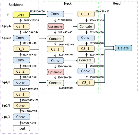
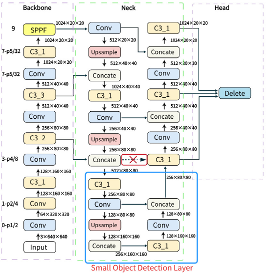
Figure 2. yolov5s network structure
Figure 2(a) shows the original YOLOv5s network structure, it is mainly composed of Backbone, Neck and Head.
The detection head of YOLOv5 outputs three different feature maps, which are used to detect large, medium, and small targets in the image. The YOLOv5s detection algorithm has weak performance in detecting small targets from the perspective of drones. Considering the computing power and memory limitations, we finally choose to add a small target detection layer to the novel part of the network structure of the YOLOv5. Implementation of this approach requires modification of the YOLOv5 model file yaml.
Figure 2(b) shows the network structure after adding a small object detection layer. Specifically, the feature graph of 80 x 80 in the original network structure to obtain the feature map of 160 x 160, and then concat it with the 160 x 160 feature map of layer 2 in Backbone to obtain a feature map of 160 x 160. After downsampling, 80 x 80 feature map are obtained and passed to the detection head through C3. The final detection head integrates features from multiple layers to enhance its detection capability for targets of different sizes.
Figure 3 shows the effect of adding small target detection layer:
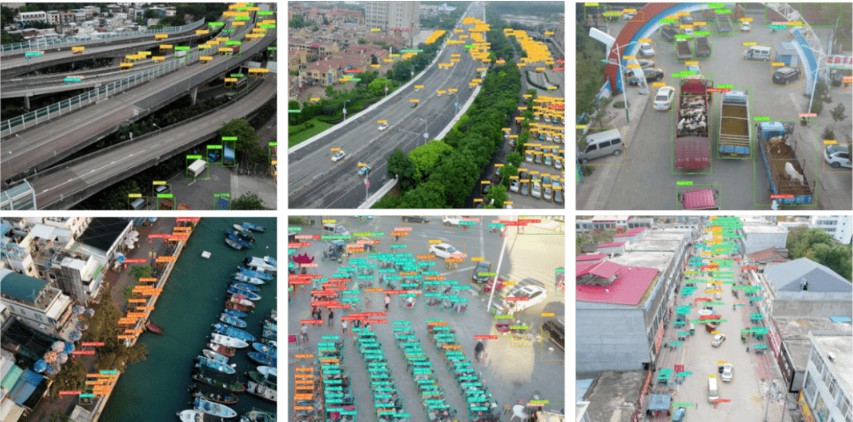
Figure 3. Effect of adding small target detection layer
Before training the model, we also performed data enhancement on the dataset to improve the diversity of data, reduce irrelevant features in the dataset, increase the amount of data and enhance the robustness of the neural network. For some of the pictures in the data set, we did random cropping, rotation, zoom and other operations to achieve data enhancement operations.
3.2. Implementations
In the specific code implementation, we make the following improvements to the network structure:
We changed Anchors, YOLOv5, Anchors is the width and height of a set of a priori boxes to initialize the model to predict the beginning of the bounding box during training, and we changed the data of Anchors to increase the Anchors for smaller targets to improve monitoring efficiency and accuracy.
1 | anchors: |
2 | -[4,5, 8,10, 22,18]# P2/4 |
3 | -[10,13, 16,30, 33,23] # P3/8 |
4 | -[30,61, 62,45, 59,119] # P4/16 |
5 | -[116,90, 156,198, 373,326] #P5/32 |
The code indicates if the input image size =640X640
We changed the network structure, added and modified some layers to enhance the ability of the network, especially in feature extraction and fusion.
[Original txt pls]
At layer 17, the feature map of 80 x 80 in Neck is upsampled to 160 x 160, which facilitates further feature extraction after the size of the feature map decreases.
At layer 18-20, the acquired feature map of size 160X160 and the feature map of layer 2160 x 160 in Backbone are concat fused to obtain a larger 160 x 160 feature map. Improve the ability to detect small targets.
At layers 21 - 29, C3 and convolutional layers were added to further extract and fuse features. Improve the network robustness.
At layer 31, layer Detect, it receives feature maps from different scales (21,24,27,30), which are enhanced by previous modification and optimization.
3.3. Experiments and Evaluation Index
Hardware configuration of the experimental environment:
GPU:RTX 4090D(24GB)*1 ;
CPU:18VCPU AMD EPYC 9754 128-Core Processor
Compiling environment:
PyTorch 1.9.0
Python 3.8(ubuntu18.04)
Cuda 11.1
Our experiment uses a dataset based on the UAVVaste dataset, which is garbage data captured from the perspective of unmanned aerial vehicles. The dataset contains 772 images and 3716 annotations. On this basis, we took many photos ourselves using drones and added them to the dataset to form a new dataset, which was annotated in YOLO format. The final dataset contains 1136 garbage images from the perspective of drones. The dataset used in the experiment is shown in Figure 4.
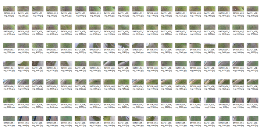
Figure 4. The dataset used in the experiment
There are two important detection indicators in the target detection, namely IoU and mAP. IoU is the intersection ratio, indicating the degree of coincidence between the prediction result box and the manual label box, and mAP is the average of each category of AP, which involves the confusion matrix theory.
Figure 5 represents the confusion matrix. TP indicates positive sample prediction and is also positive sample; FP indicates negative sample but predicts positive sample; TN indicates negative sample prediction and negative sample; FN indicates positive sample prediction and negative sample.
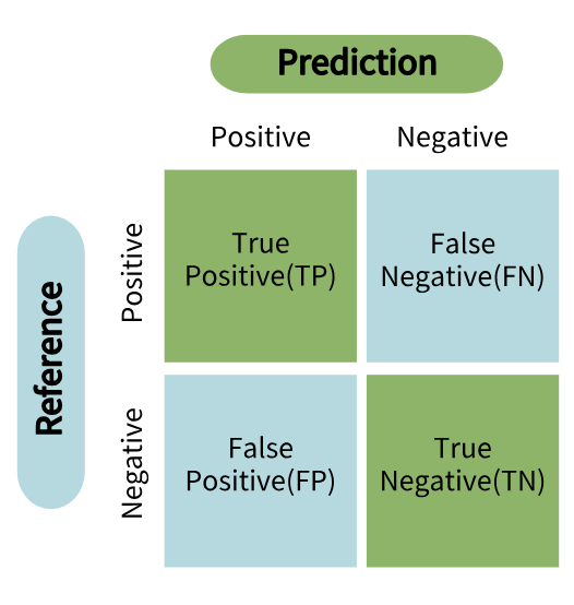
Figure 5. The confusion matrix
1 | |
2 | anchors: |
3 | - [4,5, 8,10, 22,18]# P2/4#an additional set of small-sized anchors, used for detection larger than 4 x 4 |
4 | - [10,13, 16,30, 33,23] # P3/8 |
5 | - [30,61, 62,45, 59,119] # P4/16 |
6 | - [116,90, 156,198, 373,326]# P5/32 |
7 | |
8 | # YOLOv5 v6.0 backbone |
9 | backbone |
10 | [[-1,1, Conv, [64, 6, 2, 2]],#0 Convolutional Layer [64,320,320 ] |
11 | [-1,1,Conv, [128,3,2]],#1Convolutional Layer [128,160,160] |
12 | [-1,3,C3, [128]],#2 C3 [128,160,160] |
13 | |
14 | [-1,1,Conv, [256,3,2]],#3Convolutional Layer [256,80,80 |
15 | [-1,6,C3, [256]],#4C3 [256,80,80] |
16 | |
17 | [-1,1,Conv, [512, 3, 2]],#5Convolutional Layer [512,40,40] |
18 | [-1,9,C3, [512]],#6C3 [512,40,40] |
19 | |
20 | [-1,1,Conv, [1024, 3, 2]],#7Convolutional Layer [1024,20,20] |
21 | [-1,3,C3, [1024]],#8C3 [1024,20,20] |
22 | [-1,1,SPPF, [1024, 5]],#9SPPF[1024,20,20] |
23 | ] |
24 | |
25 | head. |
26 | #neck |
27 | #[512,20,20] |
28 | [[-1, 1, Conv, [512, 1, 1]],#10 Convolutional Layer[512,20,20] |
29 | [-1, 1, nn.Upsample, [None,2, ’nearest’]], #11Upsampling [512,40,40] |
30 | [[-1, 6], 1, Concat, [1]],#12 Concat [1024,40,40] |
31 | |
32 | [-1, 3, C3, [512, False]],#13 C3[512,40,40] |
33 | [-1, 1, Conv, [256, 1, 1]], #14 Convolutional Layer[256,40,40] |
34 | [-1, 1, nn.Upsample, [None, 2, ’nearest’]], #15 Upsampling [256,80,80] |
35 | [[-1, 4], 1, Concat, [1]], #16 Concat[512,80,80] |
36 | #[-1, 3, C3, [256, False]],# deleted |
37 | |
38 | #our own layers |
39 | [-1, 3, C3, [256, False]], #17 C3 [256,80,80] |
40 | [-1, 1, Conv, [128, 1, 1]], #18 Convolutional Layer [128,80,80] |
41 | [-1, 1, nn.Upsample, [None, 2, ’nearest’]],#19 Upsampling [128,160,160] |
42 | [[-1, 2], 1, Concat, [1]],#20 Concat [512,160,160] |
43 | |
44 | #head |
45 | [-1, 3, C3, [128, False]],#21 C3 [128,160,160] |
46 | [-1, 1, Conv, [128, 3, 2]],#22 Convolutional Layer[128,80,80] |
47 | [[-1, 18], 1, Concat, [1]],#23 Concat [512,160,160] |
48 | [-1, 3, C3, [256, False]], #24 C3 [256,160,160] |
49 | [-1, 1, Conv, [256, 3, 2]],#25Convolutional Layer [256,40,40] |
50 | [[-1, 14], 1, Concat, [1]],#26 Concat [512,160,160] |
51 | |
52 | [-1, 3, C3, [512, False]],#27 C3[512,40,40] |
53 | [-1, 1, Conv, [512, 3, 2]],#28 Convolutional Layer [512,20,20] |
54 | [[-1, 10], 1, Concat, [1]],#29 Concat [1024,20,20] |
55 | [-1, 3, C3, [1024, False]],#30 C3[1027,20,20] |
56 | |
57 | [[21, 24, 27, 30], 1, Detect, [nc, anchors]], |
58 | ] |
Anchor Configurations for YOLOv5 Model
The accuracy (PR) values are calculated as follows:
\( P{R_{ca}}=\frac{T{P^{←}}}{TP+F{P^{←}}} \) (1)
The AP value is the graph area surrounded by the PR curve and the coordinate axis. mAP is the average AP of all categories of all the pictures in the data set. N is the number of categories:
\( mAP=\frac{\sum _{i=1}^{N}A{P_{i}}}{N} \) (2)
In the following text, we will refer to the yolov5s model with a small object detection layer as yolov5s*, and conduct experimental comparisons between yolov5s and yolov5s *
Figure 6 (a) shows the confusion matrix of the original yolov5s model, and (b) is the confusion matrix of the yolov5s *. yolov5s performs well in multiple categories, especially in the Food Packaging and Plastic Bottle categories, but has shortcomings in detecting small objects such as Plastic Bag and Paper Cup. The yolov5s * model has improved in small object detection, especially in the Plastic Bag category. Overall, the yolov5s * model has shown improvement in small object detection.
|
|
Confusion Matrix of YOLOv5s Model | Confusion Matrix of YOLOv5s* Model |
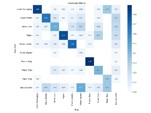
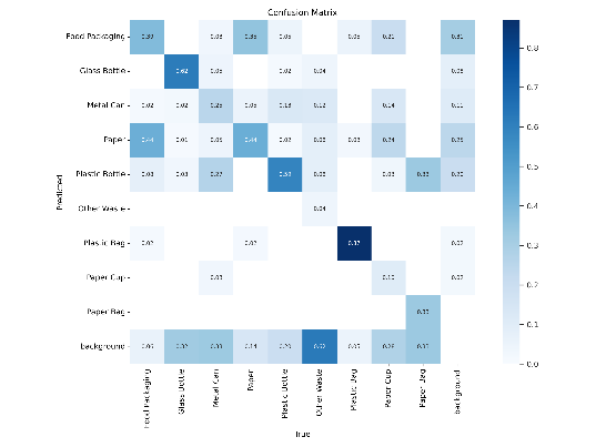
Figure 6. Comparison diagram of confusion matrix
In Figure 7, (a) and (c) represent the PR curve and recall curve of the YOLOv5s model, while (b) and (d) represent the PR curve and recall curve of the YOLOv5s * model. It can be seen that although the map of the YOLOv5s * model is slightly lower than that of the YOLOv5s model, the recall rate of the YOLOv5s model decreases rapidly at high confidence (close to 1.0), indicating that there may be missed detections at high confidence. The downward trend of the recall rate of the YOLOv5S * model at high confidence is relatively gentle, indicating that its detection ability has been enhanced at high confidence. The YOLOv5S * model has improved recall compared to the YOLOv5S model, especially in detecting small targets.
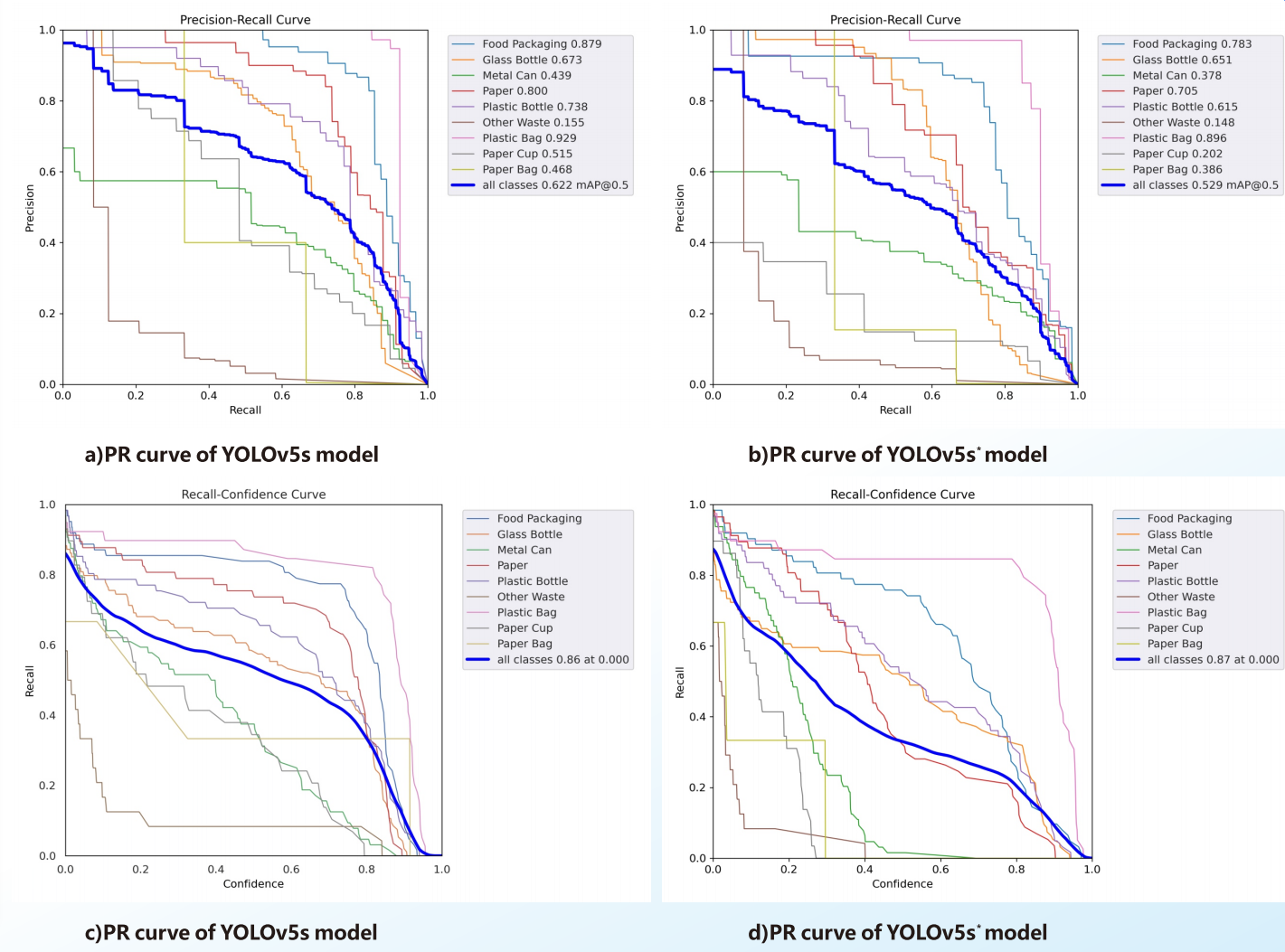
Figure 7. Precision-Recall and Recall Curves Comparison
In the 100 images of the test set, we also compared the detection performance of the YOLOv5s model and the YOLOv5s * model, and found that the YOLOv5s * model performed better than the YOLOv5s model in detecting small targets in most scenarios. As shown in Figure 8, the actual detection performance of two models in the same image is compared. (a)is the YOLOv5s model, and (b) is the YOLOv5s * model. In contrast, we clearly found significantly increased confidence in food packaging and plastic bag target detection. It can be clearly seen that YOLOv5s may have some missed detections in detecting small targets, especially when the target is small or similar to the background. Due to the addition of a small object detection layer, YOLOv5S * can better recognize small objects, and the coverage and accuracy of annotation boxes have been improved.
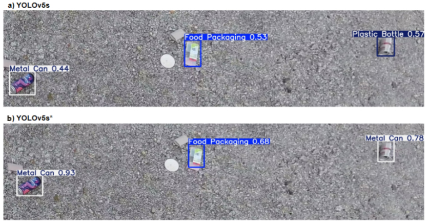
Figure 8. Comparison of actual detection results
Overall, through experimental comparisons on the dataset, we found that the YOLOv5s * model with added small object detection layer has better detection ability for small objects than YOLOv5s, which is more advantageous for object detection and localization from the perspective of our drone.
In contrast, we clearly found significantly increased confidence in food packaging and plastic bag target detection.
4. Localizing Methods
To ensure precise target localization, this section presents a distortion correction algorithm using OpenCV. This method accurately translates pixel coordinates to real-world positions, vital for our application.
4.1. Distortion correction
The image captured by the wide-angle lens may undergo distortion, which might result from various inevitable factors. Therefore adjusting and correction is needed before the object can be located in the real-world.
Traditionally, a second-order distortion model is used to describe the distortion process:
\( δx={λ_{1}}x({x^{2}}+{y^{2}})+{λ_{2}}x({x^{2}}+{y^{2}}{)^{2}} \) (3)
\( δy={λ_{1}}y({x^{2}}+{y^{2}})+{λ_{2}}y({x^{2}}+{y^{2}}{)^{2}} \) (4)
Where (x, y) is the image coordinate, (δx, δy) is the distortion vector and λ1, λ2 are the distortion coefficients.
From these formulae we can get the corrected coordinate of the pixel point is
\( x=δx={λ_{1}}x({x^{2}}+{y^{2}})+{λ_{2}}x({x^{2}}+{y^{2}}{)^{2}} \) (5)
\( y=δy={λ_{1}}y({x^{2}}+{y^{2}})+{λ_{2}}y({x^{2}}+{y^{2}}{)^{2}} \) (6)
To correct the distortion, we can calculate the distortion matrix by taking photos of a printed chessboard and reverse the distortion process, as is shown in 4.1. In our study, we utilized the Zhang’s flexible camera caliberation method to adjust our images.
The following code shows the undistortion process after the undistortion parameters are calculated
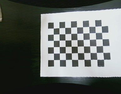
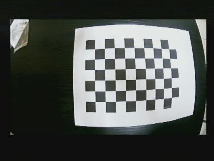
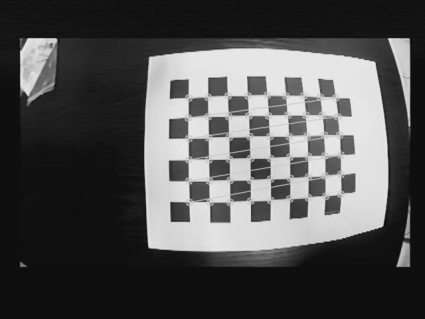
(a) Original picture(b) Processed picture(c) Adjusted picture
Figure 9. Process of adjusting the picture
In our research, we employed Zhang’s flexible camera calibration method to fine-tune and adjust our images for distortion correction. This method, developed by Zhengyou Zhang, is widely used for camera calibration and distortion correction in computer vision applications.
The following code shows the undistortion process after the undistortion parameters are calculated.
Algorithm 1 Image Distortion Correction Algorithm
Require: v : captured video stream, P : distortion parameter.
Import cv2, pickle
Initialize camera matrix M , distortion coefficients, rotation vectors, and translation vectors using P .
From v, using distortion parameter P derive area of interest (x, y, width, height).
for each frame i in v do
Undistort image i using matrix M and distortion coefficients.
Cut image i based on the region of interest (x, y, width, height).
display i
end for
4.2. Coordinate calculation
After the adjusting process, the coordinate of the object detected by the YOLO model is originally in pixel coordinate system, in the form of (row, column). But to apply in real life, the longitude and latitude must be found. To achieve that, we have to transform the coordinate from pixel coordinate to image coordinate, drone coordinate and finally to world coordinate.
1. Pixel coordinate is the data collected from the YOLO model. It indicates the object we are looking for locates in pixel of row r, column c of the image.
2. Image coordinate is the relative relationship between the target object and the center of the adjusted image. It is located at point (x, y).
3. Drone coordinate describes the relative position of the object regarding to the drone.
\( \vec{E{O^{ \prime \prime }}}=\vec{O{O^{ \prime \prime }}}×\frac{{E^{ \prime }}{O^{ \prime }}}{O{O^{ \prime }}} \) (7)
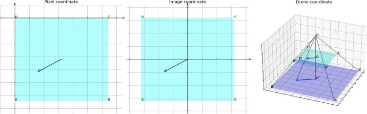
Figure 10. The Illustration of coordinate calculation
By placing different items of known length on the ground and lifting the camera to different lengths to measure the length of the objects in the picture, we can collect data to determine E′O′ .
We found that the real-world distance can be calculated using the following formula:
\( L=0.0045×n×h \) (8)
Where L is the real-world distance, n is the distance in the captured photo in pixels, and h is the height of the drone.
5. System design
The UAV system integrates advanced hardware with a user-friendly PyQt interface for real-time surveillance. This section aims to introduce our hardware and software configuations.
5.1. Hardware configuation
The drone we use is the ZD680pro, a high-performance UAV platform, providing stable flight support and sufficient load capacity, suitable for a variety of sensors and cameras.
The left image of Figure 11 shows the map transmission module mounted by the drone, which is used to transmit the video signals captured by the drone’s camera to the ground station in real time. This is critical for real-time target detection and monitoring.
The middle image of Figure 11 shows the digital transmission module of the UAV, used to transmit flight data (e.g. GPS coordinates, flight altitude, and attitude information) and to receive control commands from the ground station. Part of the data to calculate the target location is obtained through this module.
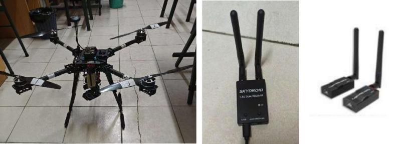
Figure 11. From left to right: self add-assembled drone, digital transmission module, image transmission module
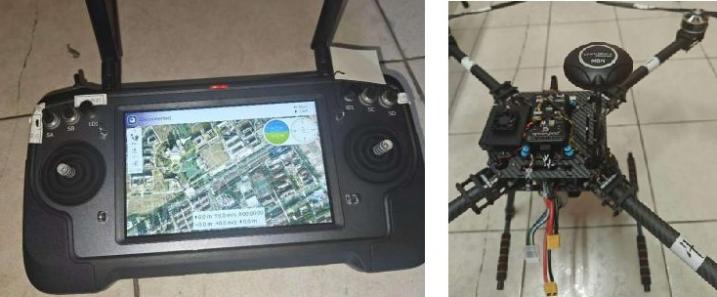
Figure 12. From left to right: remote control, GPS module
The MK 32 remote control is a high-performance device that supports multi-band operation to ensure the stability and reaction speed of long-distance control. In the project, the remote control is used to control the UAV to detect garbage.
The GPS module provides precise geographic location data for UAVs, which is crucial for performing precise target positioning and path planning. The module can provide the location information of the UAV in real time, ensuring flight safety and data accuracy.
5.2. Software design
As shown in the system flowchart in Figure 13 the drone’s camera captures real-time images and sends them to the ground station through the image transmission module. At the same time, the drone’s data transmission module at the sky end transmits the drone’s flight data to the ground end through the mavlink protocol. Then, the target detection module is used to perform small target detection on the drone image, and the pixel position information of the detected target object is sent to the target object positioning calculation module; The positioning module obtains flight data from the drone, calculates the true GPS position of the target based on its pixel location, and finally displays the detected target image and calculated GPS position on the monitoring interface.
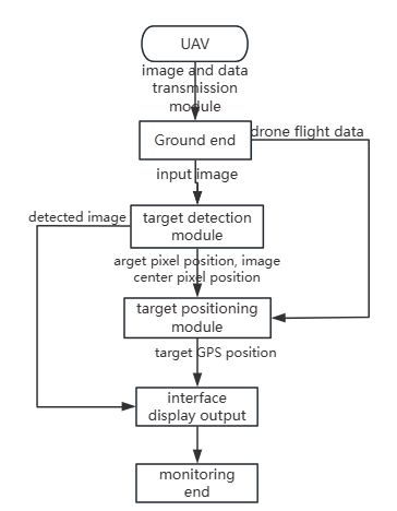
Figure 13. The System Flowchart
5.3. Interface Design and Display
Our front-end is based on an open-source project, QT for Python 6 [19]. It has a simple and concise configuration, featuring the original captured video in the upper left, processed video with a frame around the detected object in the upper right, and coordinates of the detection box at the bottom. QtWidgets.QWidget and QtWidgets.QMainWindow classes are utilized to create such configuration.
As shown in Figure 14, the system interface displays the footage captured by the drone on the left side of the upper half of the interface, the target detection result area on the right displays the detected targets and related information, and the lower half of the interface displays the calculated GPS position of each target.
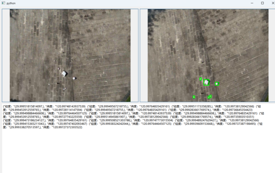
Figure 14. Interface Display
6. Discussion
6.1. Applications
The UAV system has broad applications for practical environmental monitoring and management, especially in vast areas where rapid and precise targeting are needed. Here is a discussion of some specific application scenarios and system advantages:
In river waste detection, forest waste detection and environmental pollution assessment, the UAV system can quickly cover large areas and return images and data in time, helping to help environmental scientists and managers make quick decisions. In precision agriculture, the system can be used for crop health monitoring, pest detection and crop yield estimation, realizing the fine management of agricultural production through efficient target detection and positioning technology. In terms of urban development monitoring, traffic flow analysis and other aspects, the real-time data provided by drones can help urban planners and managers to better understand urban dynamics and optimize urban management and services. In disaster response and rescue, the system can be used for specialized search and rescue, enabling the drone to quickly locate trapped people and important materials after a disaster. In security monitoring, drones can be used to carry out security monitoring and management of large-scale activities, such as sports events, large-scale public activities, etc.
However, limited to the hardware and software, the system still has the following limitations:
The performance of the system partly depends on the environmental conditions, such as extreme weather (strong wind, rain and snow), which may affect the flight stability and image quality of the UAV. The current hardware configuration, although efficient, is still limited by battery life, load capacity and transmission distance, which may affect the application of the system in some extreme or special environments.
6.2. Future work
According to the limitations of the current system and the future technology development trend, the system has some room for improvement:
1. Improve flight control algorithm and increased flight stability to better assist the camera in acquiring images.
2. A better model could be used to enhance environmental adaptability, and images in more practical application scenarios are added in the data set to improve the reliability of the system in a specific environment.
3. Improve hardware performance, such as more efficient batteries and lighter mate- rials, to extend flight time and improve load capacity.
7. Conclusion
We optimized the existing target detection and positioning algorithms, and carried the system with the above algorithms to the UAV to realize the function of searching and locating garbage in the vast areas. In terms of target detection, based on the yolov5 model, we added a small target detection layer on top, and increased the ability of small target detection to fit the characteristics that the target scale decreases with increasing height in the images acquired by the UAV. In terms of positioning, we adjusted the image acquired by the wide-angle camera by calculating the distortion matrix, and then obtained the target position by calculating the mapping relationship between the target position in the image and the position in the real world and combining the longitude and latitude position of the UAV. In addition, we developed a user interface based on PyQt 5, which obtains data from the sky side and visually gives feedback on the back-end processing results.
References
[1]. ZHANG F, ZHAO Y, WANG D, et al. Current technologies for plastic waste treatment: A review[J/OL]. Journal of Cleaner Production, 2021, 282: 124523. https://www.sciencedirect.com/science/article/pii/S0959652620345674. DOI: https://doi.org/10.1016/j.jclepro.2020.124523.
[2]. HAN L, WANG T, YAO Y. “white pollution”and pollution treatment[J]. China Population,Resources and Environment, 2010, 20(S1): 402-404.
[3]. ROCHMAN C M, BROWNE M A, HALPERN B S, et al. Classify plastic waste as hazardous[J]. Nature, 2013, 494(7436): 169-171.
[4]. LAW K L. Plastics in the marine environment[J/OL]. Annual review of marine science, 2017, 9(1): 205-229. DOI: https://doi.org/10.1146/annurev-marine-010816-060409.
[5]. KNOBLAUCH D, MEDERAKE L. Government policies combatting plastic pollu- tion[J]. Current opinion in toxicology, 2021, 28: 87-96.
[6]. BORRELLE S B, RINGMA J, LAW K L, et al. Predicted growth in plastic waste exceeds efforts to mitigate plastic pollution[J]. Science, 2020, 369(6510): 1515-1518.
[7]. LIU Y, SUN P, WERGELES N, et al. A survey and performance evaluation of deep learning methods for small object detection[J]. Expert Systems with Applications, 2021, 172: 114602.
[8]. PARK S, CHOI Y. Applications of unmanned aerial vehicles in mining from explo- ration to reclamation: A review[J]. Minerals, 2020, 10(8): 663.
[9]. DUTTA G, GOSWAMI P. Application of drone in agriculture: A review[J]. Inter- national Journal of Chemical Studies, 2020, 8(5): 181-187.
[10]. FAN B, LI Y, ZHANG R, et al. Review on the technological development and application of uav systems[J]. Chinese Journal of Electronics, 2020, 29(2): 199-207.
[11]. Viola P, Jones M J. Robust real-time face detection[J]. International journal of computer vision, 2004, 57: 137-154.
[12]. HAN X, CHANG J, WANG K. You only look once: unified, real-time object detection[J].Procedia Computer Science, 2021, 183(1): 61-72.
[13]. Liu W, Anguelov D, Erhan D, et al. Ssd: Single shot multibox detector[C]//Computer Vision–ECCV 2016: 14th European Conference, Am sterdam, The Netherlands, October 11–14, 2016, Proceedings, Part I 14. Springer International Publishing, 2016: 21-37.
[14]. YAEGER L, LYON R, WEBB B. Effective training of a neural network character classifier for word recognition[J]. Advances in neural information processing systems, 1996, 9.
[15]. WANG D, LIAO C, MOU J. Feature fusion-based small target detection for ssd vision[J].Computer Engineering and Applications, 2020, 56(16)(21-25).
[16]. QIAN L, GANG L, LE Z, et al. Positioning algorithm of a certain type of drone[J].Firepower and control, 2008, 33(9): 57-59.
[17]. Qiao C, Ding Y, Xu Y, et al. Ground target geolocation based on digital elevation model for airborne wide-area reconnaissance system[J]. Journal of Applied Remote Sensing, 2018, 12(1): 016004-016004.
[18]. Zhizhuo W. Principles of photogrammetry (with remote sensing)[J]. (No Title), 1990.
[19]. ANONYMUS. Qt for python[EB/OL]. https://doc.qt.io/qtforpython-6/.
Cite this article
Zhou,C.;Yu,T. (2024). AI-empowered Search Drone: Advanced AI-based Tiny Object Search Drone for Broad Areas. Applied and Computational Engineering,95,274-288.
Data availability
The datasets used and/or analyzed during the current study will be available from the authors upon reasonable request.
Disclaimer/Publisher's Note
The statements, opinions and data contained in all publications are solely those of the individual author(s) and contributor(s) and not of EWA Publishing and/or the editor(s). EWA Publishing and/or the editor(s) disclaim responsibility for any injury to people or property resulting from any ideas, methods, instructions or products referred to in the content.
About volume
Volume title: Proceedings of the 6th International Conference on Computing and Data Science
© 2024 by the author(s). Licensee EWA Publishing, Oxford, UK. This article is an open access article distributed under the terms and
conditions of the Creative Commons Attribution (CC BY) license. Authors who
publish this series agree to the following terms:
1. Authors retain copyright and grant the series right of first publication with the work simultaneously licensed under a Creative Commons
Attribution License that allows others to share the work with an acknowledgment of the work's authorship and initial publication in this
series.
2. Authors are able to enter into separate, additional contractual arrangements for the non-exclusive distribution of the series's published
version of the work (e.g., post it to an institutional repository or publish it in a book), with an acknowledgment of its initial
publication in this series.
3. Authors are permitted and encouraged to post their work online (e.g., in institutional repositories or on their website) prior to and
during the submission process, as it can lead to productive exchanges, as well as earlier and greater citation of published work (See
Open access policy for details).
References
[1]. ZHANG F, ZHAO Y, WANG D, et al. Current technologies for plastic waste treatment: A review[J/OL]. Journal of Cleaner Production, 2021, 282: 124523. https://www.sciencedirect.com/science/article/pii/S0959652620345674. DOI: https://doi.org/10.1016/j.jclepro.2020.124523.
[2]. HAN L, WANG T, YAO Y. “white pollution”and pollution treatment[J]. China Population,Resources and Environment, 2010, 20(S1): 402-404.
[3]. ROCHMAN C M, BROWNE M A, HALPERN B S, et al. Classify plastic waste as hazardous[J]. Nature, 2013, 494(7436): 169-171.
[4]. LAW K L. Plastics in the marine environment[J/OL]. Annual review of marine science, 2017, 9(1): 205-229. DOI: https://doi.org/10.1146/annurev-marine-010816-060409.
[5]. KNOBLAUCH D, MEDERAKE L. Government policies combatting plastic pollu- tion[J]. Current opinion in toxicology, 2021, 28: 87-96.
[6]. BORRELLE S B, RINGMA J, LAW K L, et al. Predicted growth in plastic waste exceeds efforts to mitigate plastic pollution[J]. Science, 2020, 369(6510): 1515-1518.
[7]. LIU Y, SUN P, WERGELES N, et al. A survey and performance evaluation of deep learning methods for small object detection[J]. Expert Systems with Applications, 2021, 172: 114602.
[8]. PARK S, CHOI Y. Applications of unmanned aerial vehicles in mining from explo- ration to reclamation: A review[J]. Minerals, 2020, 10(8): 663.
[9]. DUTTA G, GOSWAMI P. Application of drone in agriculture: A review[J]. Inter- national Journal of Chemical Studies, 2020, 8(5): 181-187.
[10]. FAN B, LI Y, ZHANG R, et al. Review on the technological development and application of uav systems[J]. Chinese Journal of Electronics, 2020, 29(2): 199-207.
[11]. Viola P, Jones M J. Robust real-time face detection[J]. International journal of computer vision, 2004, 57: 137-154.
[12]. HAN X, CHANG J, WANG K. You only look once: unified, real-time object detection[J].Procedia Computer Science, 2021, 183(1): 61-72.
[13]. Liu W, Anguelov D, Erhan D, et al. Ssd: Single shot multibox detector[C]//Computer Vision–ECCV 2016: 14th European Conference, Am sterdam, The Netherlands, October 11–14, 2016, Proceedings, Part I 14. Springer International Publishing, 2016: 21-37.
[14]. YAEGER L, LYON R, WEBB B. Effective training of a neural network character classifier for word recognition[J]. Advances in neural information processing systems, 1996, 9.
[15]. WANG D, LIAO C, MOU J. Feature fusion-based small target detection for ssd vision[J].Computer Engineering and Applications, 2020, 56(16)(21-25).
[16]. QIAN L, GANG L, LE Z, et al. Positioning algorithm of a certain type of drone[J].Firepower and control, 2008, 33(9): 57-59.
[17]. Qiao C, Ding Y, Xu Y, et al. Ground target geolocation based on digital elevation model for airborne wide-area reconnaissance system[J]. Journal of Applied Remote Sensing, 2018, 12(1): 016004-016004.
[18]. Zhizhuo W. Principles of photogrammetry (with remote sensing)[J]. (No Title), 1990.
[19]. ANONYMUS. Qt for python[EB/OL]. https://doc.qt.io/qtforpython-6/.