


1. Introduction
Resolvers are robust and reliable transducers comparing with other transducers. The non contact design between rotor and stator make it works well even in harsh environments like high temperature and high electrical magnetic noise. The resolver is basically a rotary transformer which has the rotor part fixed on the motor shaft and the reference signal coil and position-feedback orthogonal coils integrated on the stator part of the motor. The output of orthogonal coils signal is simply a multiplication of the rotation angle of rotor and the reference signal. To acquire the real-time phase and frequency information of rotor, we need to decode the feedback signal in the sine and cosine coils in a fast and appropriate way.
V_{ref}=Vsin(ω_{c}t)\ \ \ (1)
V_{cos}=g_{v}V_{ref}\cos{(θ)}\ \ \ (2)
V_{sin}=g_{v}V_{ref}\sin{(θ)}\ \ \ (3)
Where g_v is the transformation ratio between stator and rotor windings, \theta_r=\omega_rt is the rotor position and \omega_r is the rotor speed. The excitation signal is given by equation (1) in which the frequency of \omega_c is a much higher than \omega_r . For this, the edge can be detected in a much smaller period without influence the accuracy.
Fig.1 shows the stator and rotor parts of resolver from TE.

Figure 1. TE resolver stator and rotor
2. Proposed method
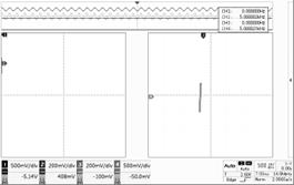
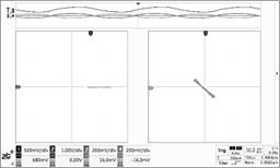
Table 1. Reference signal, Sine/Cosine signals with the rotor in different position.
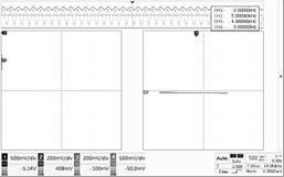 |  |
I zero degrees | II 90 degrees |
 | 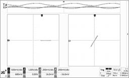 |
III 135 degrees | IV 225 degrees |
Table1 shows the traditional way of calculation the phase of rotor based on the sine and cosine signals. The reference signal is input through channel one. The scope is set to XY mode with the channel three and channel four set to sine coil input and cosine coil input. When the rotor is rotating, the angle of the plot will track the movement.
Fig.2. shows two multipliers are used to animate the resolver signal from the SINE and COSINE coils. The carrier frequency is set to 3.6k HZ and the ROTOR frequency is set to 100HZ. It is intentionally set this way for the angle phase calculation scaled to 0-360°. When the Rotor frequency and carrier frequency is set to other frequency. It still works with this methodology. A demodulation method has been talked in[1],but due to the precision of circuit, there will be distortion around the crossing zero area. The upper part is a rising edge generator to sample the pulses level for the output of three comparators. For a normal way to acquiring the rotor phase based on the resolver encoder, ADCs, Demodulation circuit, Inverse tangent function and Look up table would be included. The system is much more expensive and very complicated to be built. Here a pure digital method is proposed and the speed of this circuit is quite satisfied. A SVPWM method based segment distribution can be extended from the present research. Fig.3 shows the 3 input to 6 output logic circuit to produce the four quadrant period signal based on the output pulses from the three comparators. There are many papers have presented circuit diagram to get the resolver processed signals which include a lot of amplifiers.[2-4].Here a simpler 3-8 decoder has been used to reduce the cost.
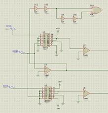 | 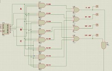 | |
Figure 2. Resolver signal animation and the reference pulse generation | Figure 3. The phase angle edge generation |
Fig.4 shows the TTL decade counter which is used to accumulate the phases from the comparator pulse. A PE12016G chip can also placed here for direction or displacement of an axis determination based on the demodulated two orthogonal signals in Fig.5. Alternatively, the pulse width can be measured by the known fixed carrier clock rate. The reset pulsed is generated from the 0-90 quadrant and the 270-360 quadrant when the rotor position is right at 360 degrees.
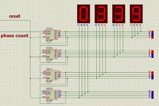 | 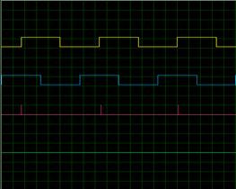 | |
Figure 4. Angle generation | Figure 5. Demodulated signal generated orthogonal pulses |
3. Experiment
Based on the circuits presented in the previous section, the simulation is performed on the Proteus. Fig.6 shows the animated resolver output signal from sine coil and the other three output pulse from the comparators. Fig.7 shows the four quadrants period signal which is also realized in [5].The comparators were constructed by precise comparator EL2018B. The multiplier is constructed by using AD734S.The TTL decade counter is built by 74LS390.The Schmitt triggers and XOR gates which can be chosen from general components as long as they can fit for the time requirement. A further experiment to this circuit can be application of a dynamic resolver signal to acquire the dynamic performance of this design.
Fig.8 shows the sampling pulse for the three output pulses. Fig.9 shows the one integrator can be used to integrate the phase signal for 0-360°Saw tooth wave generation.
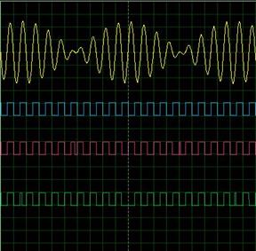 |  | |
Figure 6. Sine coil output signal and three pulses | Figure 7. Four quadrants period signal | |
 | 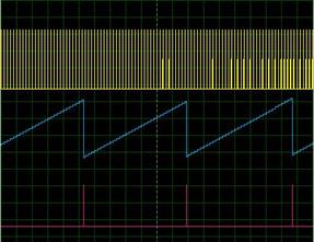 | |
Figure 8. Sampling pulse and the resolver to digital pulse signal | Figure 9. Integrator used for saw tooth wave generation |
4. Conclusion
In this paper, a new simple resolver to digital conversion method is proposed. This circuit can apply to different frequency and have a fast response to it. The digital segments give the degree of the rotor in a steady system. The system character due to the frequency step and phase step will illustrate in a future study.
References
[1]. Joseph W.Halina,& Burlingame, Calif,( 1961). SYNCHRONOUS DEMODULATION SYSTEM, U.S.Patent 2979611.
[2]. Mohieddine Benammar, & Antonio S.P.Gonzales Jr,(2013). A Novel Resolver Converter Based on a Modified Tracking Method ,ICNSC( pp.433-438).
[3]. Mohieddine Benammar, & Antonio S.P.Gonzales (2013). A new fast tracking resolver for mechanical angle measurement, AFRICON( pp.192-197).
[4]. Mohieddine Benammar, Lazhar Ben-Brahim, & Mohd A.alhamadi.(2004). A Novel Resolver-to-360°Linearized Converter, IEEE SENSORS JOURNAL(pp.96-101).
[5]. Anucha kaewpoonsuk, Ratchanoo katman, Thawatchai Kamsri, Apinai Rerkratn & Vanchar Riewruja, (2010). A simple Amplitude Detector-based Demodulator for Resolver Converters”,ICCAS(pp.389-394).
Cite this article
Chen,S.;Zhao,F. (2024). A New Way of Resolver to Digital Converter in a Steady System. Applied and Computational Engineering,109,145-149.
Data availability
The datasets used and/or analyzed during the current study will be available from the authors upon reasonable request.
Disclaimer/Publisher's Note
The statements, opinions and data contained in all publications are solely those of the individual author(s) and contributor(s) and not of EWA Publishing and/or the editor(s). EWA Publishing and/or the editor(s) disclaim responsibility for any injury to people or property resulting from any ideas, methods, instructions or products referred to in the content.
About volume
Volume title: Proceedings of the 2nd International Conference on Machine Learning and Automation
© 2024 by the author(s). Licensee EWA Publishing, Oxford, UK. This article is an open access article distributed under the terms and
conditions of the Creative Commons Attribution (CC BY) license. Authors who
publish this series agree to the following terms:
1. Authors retain copyright and grant the series right of first publication with the work simultaneously licensed under a Creative Commons
Attribution License that allows others to share the work with an acknowledgment of the work's authorship and initial publication in this
series.
2. Authors are able to enter into separate, additional contractual arrangements for the non-exclusive distribution of the series's published
version of the work (e.g., post it to an institutional repository or publish it in a book), with an acknowledgment of its initial
publication in this series.
3. Authors are permitted and encouraged to post their work online (e.g., in institutional repositories or on their website) prior to and
during the submission process, as it can lead to productive exchanges, as well as earlier and greater citation of published work (See
Open access policy for details).
References
[1]. Joseph W.Halina,& Burlingame, Calif,( 1961). SYNCHRONOUS DEMODULATION SYSTEM, U.S.Patent 2979611.
[2]. Mohieddine Benammar, & Antonio S.P.Gonzales Jr,(2013). A Novel Resolver Converter Based on a Modified Tracking Method ,ICNSC( pp.433-438).
[3]. Mohieddine Benammar, & Antonio S.P.Gonzales (2013). A new fast tracking resolver for mechanical angle measurement, AFRICON( pp.192-197).
[4]. Mohieddine Benammar, Lazhar Ben-Brahim, & Mohd A.alhamadi.(2004). A Novel Resolver-to-360°Linearized Converter, IEEE SENSORS JOURNAL(pp.96-101).
[5]. Anucha kaewpoonsuk, Ratchanoo katman, Thawatchai Kamsri, Apinai Rerkratn & Vanchar Riewruja, (2010). A simple Amplitude Detector-based Demodulator for Resolver Converters”,ICCAS(pp.389-394).