


1. Introduction
With the economic transformation and upgrading, China’s aging population is accelerating rapidly, characterized by a “late start but rapid development.” It is estimated that by 2035, China’s elderly population aged 60 and above will exceed 424 million, with the aging rate reaching 30.31%. Consequently, the health security of the elderly population requires further attention[1]. For a long time, stroke has posed a serious threat to the quality of life and safety of elderly individuals, significantly affecting their well-being. According to the Report on Cardiovascular Health and Diseases in China, the mortality rate of cerebrovascular diseases in China has been continuously rising from 2003 to 2021, ranking among the top three causes of death for Chinese residents in 2021[2]. Due to the high disability rate associated with stroke, the future quality of life of elderly stroke patients largely depends on the effectiveness of rehabilitation during the recovery period. In addition, spinal cord injuries and related neurological damages are also major causes of disability. However, the increasing gap between the growing number of paralyzed patients and the limited number of rehabilitation physicians, coupled with saturated waiting lists, makes it increasingly difficult for traditional manual-assisted rehabilitation therapies to meet current demands[3][4]. Consequently, research, design, and production of lower limb exoskeleton rehabilitation robots have been initiated across various regions to mitigate the mismatch between healthcare supply and demand and to improve the efficiency and effectiveness of treatment for paralyzed patients.
Since the development of exoskeleton robots began in the 1960s, a clear classification of the overall structure has emerged: standing and recumbent types. Standing lower limb exoskeleton rehabilitation robots are further categorized into treadmill-based and independently wearable types based on their usage and training methods[4].
Among them, the treadmill-based models include notable research achievements such as the “LOKOMAT Gait Training Rehabilitation Robot,” developed jointly by Swiss company Hocoma and ETH Zurich[5]; the “ALEX Rehabilitation Training Robot” developed by the University of Delaware in the United States[6]; the “LOPES Rehabilitation Robot” developed by the University of Twente in the Netherlands[7]; and the LokoHelp lower limb rehabilitation robot developed by Germany’s WOODWAY company[8]. These treadmill-based training platforms provide patients with a safe and controllable rehabilitation environment, ensuring a gradual recovery of gait through integrated control algorithms.

Figure 1: Treadmill-Based Lower Limb Exoskeleton Rehabilitation Robots: a) LOKOMAT Gait Training Rehabilitation Robot. b) ALEX Rehabilitation Training Robot. c) LOPES Rehabilitation Robot. d) LokoHelp Lower Limb Rehabilitation Robot.
Representative research outcomes of independently wearable exoskeleton systems include the “eLEGS Exoskeleton System” developed by the Biomechanics Lab at the University of California, Berkeley[9]; the ReWalk Exoskeleton Robot, co-developed by Harvard University’s Wyss Institute and ReWalk Robotics[10]; and the “HAL-5 Exoskeleton Rehabilitation Training Robot” developed by the University of Tsukuba in Japan[11]. These wearable exoskeleton devices, compared to treadmill-based systems, emphasize lightweight design and feature portability and comfort.
The representative achievements of recumbent exoskeleton rehabilitation robots include the “MotionMaker Exoskeleton Rehabilitation Robot” developed by the Swiss Federal Institute of Technology in Lausanne (EPFL)[12], the “TEM LX2 typeD Lower Limb Rehabilitation Robot” developed by Japan’s Yaskawa Electric Corporation[13], and the “iLeg Rehabilitation Robot” developed by the Institute of Automation of the Chinese Academy of Sciences[14]. Compared to standing exoskeleton rehabilitation robots, recumbent exoskeleton robots offer adjustable leg support lengths, providing broader adaptability and greater comfort to meet the training needs of various rehabilitation stages.
Based on different gait training methods and equipment structures, lower limb exoskeleton rehabilitation robots utilize various human information collection technologies, adopting targeted control strategies and algorithmic logic to extract, analyze, and provide feedback on the wearer’s movement information, thereby ensuring that patients undergoing rehabilitation can complete gait restoration tasks. Meanwhile, precise human-machine interaction control technologies can detect terrain obstacles and fall risks, preventing severe secondary injuries to patients. Therefore, analyzing the human-machine interaction control of lower limb exoskeleton rehabilitation robots holds significant research and application value.
2. Kinematic and Dynamic Analysis
To achieve precise human-machine interaction control for lower limb exoskeleton robots, it is essential to fully understand the information regarding the end posture, joint angles, angular velocities, angular accelerations, and driving torques. Therefore, a dynamic and kinematic analysis of the exoskeleton’s joint models and movement characteristics is indispensable. Considering the complexity of gait movement in rehabilitation training, the most representative joints of the human lower limb—the hip and knee joints—are selected as the corresponding rotational joints for the exoskeleton. A planar two-link mechanism is constructed, as shown in Figure 2. Additionally, given the symmetry of the lower limb exoskeleton, modeling and analyzing this simplified single-leg structure can sufficiently meet the information input requirements for human-machine interaction control.
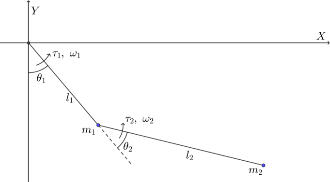
Figure 2: Simplified Two-Link Mechanism of the Lower Limb Exoskeleton.
2.1. Kinematic Analysis
To accurately obtain the end position information of the lower limb exoskeleton robot, the hip joint is selected as the reference point. The coordinates of the robot’s end-effector in the planar two-link scenario are derived, as shown in Equation (1).
\( [\begin{matrix}x \\ y \\ \end{matrix}]=[\begin{matrix}sin({θ_{1}}) & sin({θ_{1}}+{θ_{2}}) \\ -cos({θ_{1}}) & -cos({θ_{1}}+{θ_{2}}) \\ \end{matrix}][\begin{matrix}{l_{1}} \\ {l_{2}} \\ \end{matrix}] \) | (1) |
In the model, \( l, θ, τ, ω \) represent the corresponding link length, joint angle variable, joint driving torque, and joint angular velocity, respectively. The sign convention for \( θ, τ, ω \) is positive in the counterclockwise direction, where \( {θ_{1}} \) is the angle value starting from the negative y-axis, and \( {θ_{2}} \) is the angle value starting from the direction of link \( {l_{1}} \) . Forward kinematic analysis establishes the relationship between joint angle parameters and mechanism position information based on the link lengths of various lower limb exoskeleton models to accommodate differences in body parameters across different populations. At the same time, position information is calculated in real-time using angle sensors, providing the essential foundation for feedback control to coordinate joint movements.
o determine the actuator’s path and position information at each moment based on the gait algorithm, the joint angle requirements are obtained. The diagram is illustrated in Figure 3, where x and y are the coordinates of the end-effector. The results are shown in Equations (2) and (3).
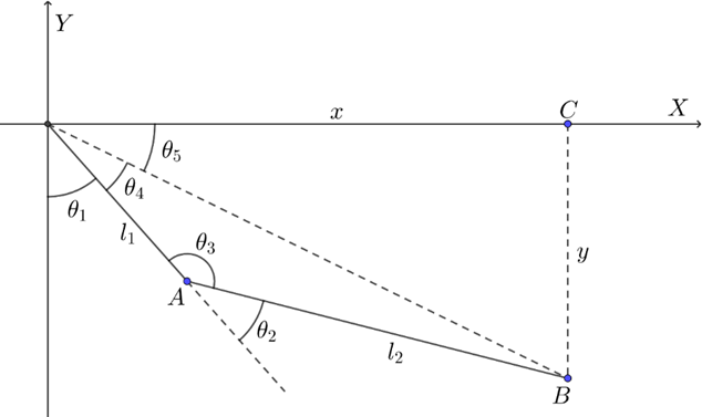
Figure 3: Inverse Kinematic Solution for Joint Variables.
\( \begin{cases} \begin{array}{c} {θ_{5}}=arcsin{(\frac{y}{x})}, cos(x) \gt 0 \\ {θ_{5}}=arcsin{(\frac{y}{x})}+π, cos(x) \lt 0 \end{array} \end{cases} \) | (1) |
\( \begin{cases} \begin{array}{c} {θ_{2}}=arccos(\frac{{x^{2}}+{y^{2}}-(l_{1}^{2}+l_{2}^{2})}{2{l_{1}}{l_{2}}}) \\ {θ_{4}}=arcsin(\frac{{l_{2}}sin({θ_{2}})}{\sqrt[]{{x^{2}}+{y^{2}}}}) \\ {θ_{1}}=\frac{π}{2}+{θ_{5}}-{θ_{4}} \end{array} \end{cases} \) | (1) |
The solutions above result in two sets: one for convex polygons and one for concave polygons. In the two-link mechanism shown in Figure 2, the quadrilateral \( OABC \) formed by the four sides and diagonal \( OB \) does not have a fixed shape; therefore \( {θ_{4}} \) can take on two values (positive and negative), leading to ambiguity in determining \( {θ_{1}} \) .
However, such ambiguity is not acceptable in the interaction control of lower limb exoskeleton robots. Given the high sampling frequency typical in exoskeleton robots, the change in joint position \( ∆θ \) between two consecutive samples should be minimal. If no constraints are placed on the calculation of \( {θ_{1}} \) , its uncertainty could result in \( ∆θ=2{θ_{4}} \) , causing the joint angular velocity computed by the control system to exceed the expected range, potentially leading to oscillations or even damage to the mechanism. Therefore, the control algorithm must constrain the calculated joint angles based on the previous position to prevent adverse outcomes.
Next, based on the forward kinematic analysis described above, a differential position equation is established. Considering \( θ \) as a single-valued function of \( t \) , the differential position equation is differentiated with respect to \( t \) , resulting in the end-effector velocity equation in the inertial reference frame, as shown in Equation (4).
\( \begin{cases} \begin{array}{c} {v_{x}}=[{l_{1}}cos{({θ_{1}})}+{l_{2}}cos({θ_{1}}+{θ_{2}})]{ω_{1}}+{l_{2}}cos({θ_{1}}+{θ_{2}}){ω_{2}} \\ {v_{y}}=[{l_{1}}sin{({θ_{1}})}+{l_{2}}sin({θ_{1}}+{θ_{2}})]{ω_{1}}+{l_{2}}sin({θ_{1}}+{θ_{2}}){ω_{2}} \end{array} \end{cases} \) | (1) |
To further describe the relationship between the velocity parameters of the end-effector and the joint variables of the two-link mechanism, a Jacobian matrix is constructed to provide the velocity mapping from joint space to Cartesian space, as shown in Equation (2-5).
\( [\begin{matrix}{v_{x}} \\ {v_{y}} \\ \end{matrix}]=[\begin{matrix}{l_{1}}cos{({θ_{1}})}+{l_{2}}cos({θ_{1}}+{θ_{2}}) & {l_{2}}cos({θ_{1}}+{θ_{2}}) \\ {l_{1}}sin{({θ_{1}})}+{l_{2}}sin({θ_{1}}+{θ_{2}}) & {l_{2}}sin({θ_{1}}+{θ_{2}}) \\ \end{matrix}][\begin{matrix}{ω_{1}} \\ {ω_{2}} \\ \end{matrix}] \) | (1) |
In the motion planning and path selection of specific gait patterns, the Jacobian matrix can be used for singularity detection, ensuring that the lower limb exoskeleton robot does not reach a position where it loses one or more degrees of freedom, which could cause instability in the mechanism. Additionally, in sensitivity analysis, the coefficients of the Jacobian matrix indirectly indicate the sensitivity of the end-effector to changes in joint angles.
2.2. Dynamic Analysis
To investigate the relationship between joint angle parameters, angular velocity parameters, angular acceleration parameters, and joint driving torque for the lower limb exoskeleton rehabilitation robot, and to determine the driving requirements of the joint motors corresponding to different states of the end-effector, the Lagrangian method is used to conduct a dynamic analysis of the two-link mechanism. The Lagrangian equation of the system can be expressed as:
\( \begin{cases} \begin{array}{c} {τ_{1}}=\frac{d}{dt}\frac{∂k}{∂{\dot{θ}_{1}}}-\frac{∂k}{∂{θ_{1}}}+\frac{∂u}{∂{θ_{1}}} \\ {τ_{2}}=\frac{d}{dt}\frac{∂k}{∂{\dot{θ}_{2}}}-\frac{∂k}{∂{θ_{2}}}+\frac{∂u}{∂{θ_{2}}} \\ \begin{matrix}k={k_{1}}+{k_{2}} \\ u={u_{1}}+{u_{2}} \\ \end{matrix} \end{array} \end{cases} \) | (1) |
Where \( {τ_{i}} \) represents the generalized force of the system, specifically the joint torque in this context; \( {θ_{i}} and {\dot{θ}_{i}} \) are the generalized coordinates and generalized velocities of the system, referring to the joint angle and joint angular velocity, respectively. \( k and u \) denote the total kinetic energy and total potential energy of the system. The mass of the links and loads are concentrated at the joints, and the position of the end-effector of the exoskeleton is set as the zero potential energy point when \( {θ_{1}}={θ_{2}}=0 \) . For link \( {l_{1}} \) , which starts at the hip joint, and link \( {l_{2}} \) , which starts at the knee joint, their kinetic and potential energies are shown in Equation (7).
\( \begin{cases} \begin{array}{c} {k_{1}}=\frac{1}{2}{m_{1}}v_{1}^{2}+\frac{1}{2}{I_{1}}ω_{1}^{2}=\frac{1}{2}{m_{1}}l_{1}^{2}\dot{θ}_{1}^{2} \\ {k_{2}}=\frac{1}{2}{m_{2}}[(l_{1}^{2}+2{l_{1}}{l_{2}}cos{({θ_{2}})}+l_{2}^{2})\dot{θ}_{1}^{2}+(2{l_{1}}{l_{2}}cos{({θ_{2}})}+2l_{2}^{2}){\dot{θ}_{1}}{\dot{θ}_{2}}+l_{2}^{2}\dot{θ}_{2}^{2}] \\ \begin{matrix}{u_{1}}=(-{l_{1}}cos{({θ_{1}})}+{l_{1}}+{l_{2}}){m_{1}}g \\ {u_{2}}=(-{l_{1}}cos{({θ_{1}})}-{l_{2}}cos{({θ_{1}}+{θ_{2}})}+{l_{1}}+{l_{2}}){m_{2}}g \\ \end{matrix} \end{array} \end{cases} \) | (1) |
Substituting Equation (7) into the Lagrangian equation (6), the result is shown in Equation (8). Here, \( M(θ) \) represents the inertia matrix of the two-link mechanism, \( C(θ, \dot{θ}) \) denotes the centrifugal and Coriolis force vector, and \( G(θ) \) is the gravity vector. Their expressions are provided in Equations (9), (10), and (11), respectively.
\( [\begin{matrix}{τ_{1}} \\ {τ_{2}} \\ \end{matrix}]=M(θ)[\begin{matrix}{\ddot{θ}_{1}} \\ {\ddot{θ}_{2}} \\ \end{matrix}]+C(θ, \dot{θ})+G(θ) \) | (1) |
\( M(θ)=[\begin{matrix}({m_{1}}+{m_{2}})l_{1}^{2}+2{m_{2}}{l_{1}}{l_{2}}cos{({θ_{2}})}+{m_{2}}l_{2}^{2} & {m_{2}}{l_{1}}{l_{2}}cos{({θ_{2}})}+{m_{2}}l_{2}^{2} \\ {m_{2}}{l_{1}}{l_{2}}cos{({θ_{2}})}+{m_{2}}l_{2}^{2} & {m_{2}}l_{2}^{2} \\ \end{matrix}] \) | (1) |
\( C(θ, \dot{θ})=[\begin{matrix}-{m_{2}}{l_{1}}{l_{2}}sin{({θ_{2}})}\dot{θ}_{2}^{2}-2{m_{2}}{l_{1}}{l_{2}}sin{({θ_{2}})}{\dot{θ}_{1}}{\dot{θ}_{2}} \\ {m_{2}}{l_{1}}{l_{2}}sin({θ_{2}})\dot{θ}_{1}^{2} \\ \end{matrix}] \) | (1) |
\( G(θ)=[\begin{matrix}{m_{2}}{l_{2}}gsin({θ_{1}}+{θ_{2}})+({m_{1}}+{m_{2}}){l_{1}}gsin({θ_{1}}) \\ {m_{2}}{l_{2}}gsin({θ_{1}}+{θ_{2}}) \\ \end{matrix}] \) | (1) |
Based on the above dynamic analysis, the joint driving torque under different gait patterns is calculated in real-time and fed back to the human-machine interaction control system to verify the feasibility of the gait algorithm. At the same time, gait adjustments are made during rehabilitation training by setting thresholds to prevent the joint torque from being too low, which would be insufficient to drive the patient’s normal movement, or too high, which could cause secondary injuries and motor overload.
3. Research on Interaction Control Algorithms
3.1. Robot Position Control
In the position control of lower limb exoskeleton rehabilitation robots, the inverse kinematic and dynamic models of the end-effector establish the relationship between joint angles, angular velocity, angular acceleration, and joint torque. Force sensors and position sensors provide real-time feedback to the closed-loop control system, while preset gait patterns and error elimination algorithms ensure the accuracy of each path point's posture. In practical conditions, due to the limited computational speed and efficiency of processing units, it is not feasible to infinitely subdivide motion parameters at each moment. Therefore, the core of the position control algorithm lies in discretely planning the temporal functions of the motion equations and using feedback regulation to achieve smooth transitions in angular velocity and angular acceleration.
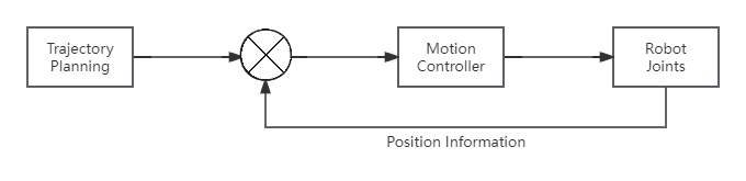
Figure 4: Schematic of Trajectory Tracking Control[15].
Trajectory tracking control, which involves planning trajectories to guide patients through predetermined gait training, is an essential strategy in position control[15]. The control process is illustrated in Figure 3. In terms of hardware and algorithm implementation, numerous control strategies are combined, including the traditional PD controller, the Linear Quadratic Regulator (LQR) optimal controller[16], and the fuzzy logic-based sliding mode controller[17].
The PD controller adjusts the control signal based on the deviation between the actual position and the desired position, using the current error and the rate of change of the error to achieve convergence of the system state toward the target trajectory. The LQR optimal controller determines the gain of the feedback controller by minimizing the performance index function and achieves smooth transitions in joint angular velocity and angular acceleration by selecting optimized state weight and control weight matrices. The sliding mode controller, by designing an appropriate sliding surface, guides the dynamic response towards the motion represented by this surface, ensuring convergence to the desired trajectory even under significant external disturbances.
3.2. Force-Position Hybrid Control
In the rehabilitation scenario for patients with lower limb injuries, exoskeleton robots conducting gait training must balance the accuracy of position tracking with the compliance of environmental interaction to prevent excessive torques applied in inappropriate directions that could cause secondary injuries to the patient. Therefore, force-position hybrid control, which integrates closed-loop position control and force control, is a crucial foundation for improving the safety and comfort of rehabilitation robots.
As shown in Figure 5, to implement force-position hybrid control, the expected parameter inputs designed based on inverse kinematics and dynamics are integrated, and the control architecture is layered. The upper-level controller combines the force control unit and the position control unit to determine the target type of the current task; the lower-level controller receives and executes the specific motion commands. Additionally, to avoid the low accuracy and limited applicability caused by model-based feedback linearization, adaptive control algorithms[18], as well as multivariable control algorithms like LQR and H \( ∞ \) [16], 从are utilized in force-position hybrid control to facilitate the selection among “position-priority mode,” “force-priority mode,” and “hybrid mode” strategies.
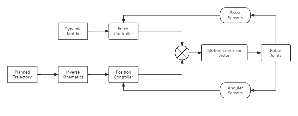
Figure 5: Schematic of Force-Position Hybrid Control.
3.3. Robot Impedance Control
In practical medical scenarios, patients have varying degrees of injury, different body parameters, and face complex and diverse rehabilitation environments, ranging from hospital assistive devices to cement pavements. Therefore, designing flexible interaction to manage contact forces is crucial for enhancing the robot’s adaptability to unknown and dynamic environments and for improving the precision of force-position interactions. Impedance control, as a mainstream compliant response control strategy, is suitable for most applications where interaction between the environment and the equipment must be considered.
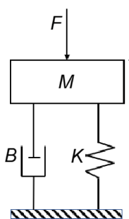
Figure 6: Mass-Spring-Damper Dynamic System.
Researchers such as Meng[19] and Chen et al.[20] have pointed out in robot system studies that the key to implementing impedance control lies in the dynamic adjustment of feedback on displacement, velocity, and acceleration information. The second-order linear impedance control law can be modeled as a mass-spring-damper system, with its expression given in Equation (12).
\( M(\ddot{x}-{\ddot{x}_{d}})+B(\dot{x}-{\dot{x}_{d}})+K(x-{x_{d}})=E(t) \) | (1) |
Here, \( M \) is the robot’s ideal inertia matrix, \( B \) is the robot’s ideal damping matrix, and \( K \) is the robot’s ideal stiffness matrix. \( {\ddot{x}_{d}} \) 、 \( {\dot{x}_{d}} \) 、 \( {x_{d}} \) represent the desired acceleration, velocity, and position of the robot’s executing joint, respectively, while \( \ddot{x} \) 、 \( \dot{x} \) 、 \( x \) denote the actual acceleration, velocity, and position of the robot’s executing joint. \( E(t) \) is the error function.
From a control structure perspective, the impedance controller typically consists of two main components: an inner-loop position controller and an outer-loop force controller. The inner-loop controller generates control inputs based on the given reference trajectory sequence \( {x_{d}} \) to ensure the end-effector tracks the expected position. The outer-loop controller adjusts the output of the inner-loop controller based on the measured contact force, ensuring that the end-effector meets the required impedance characteristics.
3.4. Bioelectrical Signal-Based Interaction Control
In the past decade, with advancements in high-resolution functional magnetic resonance imaging (fMRI) technology and progress in neuroplasticity research, the activation patterns and activity mapping of various brain regions during different cognitive processes have been deeply analyzed. This has provided a theoretical basis for bioelectrical signal-based interaction control and rehabilitation technology. Taking stroke, a condition with a high incidence rate, as an example, damage to the subcortical motor pathways during a stroke can lead to lower limb motor dysfunction[21]. The electrical signals transmitted by synapses in the brain's motor functional areas become too weak to reach the threshold required for muscle effectors. Therefore, brain-computer interface (BCI) and electromyography (EMG) interactions are integrated into the control algorithms of lower limb exoskeleton rehabilitation robots for such patients.
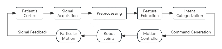
Figure 7: EEG Intention Recognition Strategy.
EEG interaction control captures the voltage fluctuations caused by the ionic flow between neurons in the brain[15] and converts them into exoskeleton control commands, allowing patients to control the lower limb exoskeleton rehabilitation robot system through thought. As shown in Figure 7, EEG interaction consists of six stages: signal acquisition, preprocessing, feature extraction, intention classification, motion execution, and feedback. In the motor cortex, an external electrode array captures the patient's motor intention signals. Next, the raw EEG signals are filtered to remove interference caused by other bodily activities, such as eye movements. Subsequently, specific motor intention features are extracted based on changes in the motor-related μ and β rhythms, as well as event-related synchronization and desynchronization. Algorithms such as artificial neural networks (ANN) are then used to classify these intention features[22]. Finally, the classified features are transformed into motion control commands to drive the lower limb muscle groups and provide feedback to the motor cortex for compensatory recovery[23].
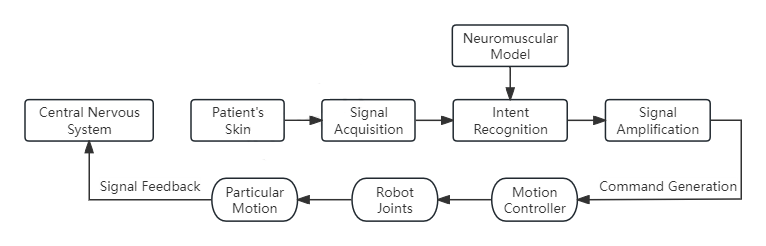
Figure 8: EMG Intention Recognition Strategy.
Skeletal muscle serves as the effector for neural signals output by the motor cortex, and the electromyographic (EMG) signals generated during its movement are directly controlled by the central nervous system. EMG interaction control captures the potential changes released by muscle fibers during movement, recognizes and amplifies the motor intentions, and assists patients in executing specific movements while promoting the repair of neurons in the motor cortex. As shown in Figure 8, EMG interaction consists of four stages: signal acquisition, intention recognition, signal enhancement, and motion execution. On the skin surface of the target muscle group, electrodes record EMG signals, which include information about muscle activation levels and timing. Subsequently, the EMG signals are extracted and interpreted using neuromuscular models for intention recognition. Once the intended features are identified, signal enhancement techniques are employed to control the joints of the exoskeleton rehabilitation robot, ultimately achieving movement in the affected limb.
4. Discussion and Conclusion
In the context of lower limb motor dysfunction due to brain nerve injuries, an analysis and summary of existing human-machine interaction control methods reveal the following: Trajectory tracking control is simple to program and can significantly reduce the uncertainty of lower limb exoskeleton rehabilitation robots, ensuring that the patient’s rehabilitation training strictly follows the preset gait trajectory. However, it places high demands on modeling accuracy and sensor precision, and the system's adaptability is relatively limited. Hybrid force-position control can respond to changes in external forces and positions, reducing the risk of falls and providing better adaptability to complex and variable terrains. However, the comprehensive consideration of force and position information increases the system design complexity and presents challenges for algorithm optimization and hardware performance. Impedance control offers strong adaptability and can provide personalized support by adjusting the system’s stiffness and damping matrices, thereby reducing the risk of secondary injuries from accidental falls. However, tuning the parameters of the stiffness, damping, and inertia matrices is challenging, and the system’s sensitivity to impedance settings is high, which may lead to oscillations in the control system. EGG signal interaction enables active control of the exoskeleton robot by directly reading motor intentions from the brain cortex, providing significant assistance for patients unable to generate muscle electrical signals. However, EEG signals are susceptible to interference from other physiological activities, leading to high preprocessing complexity. Additionally, brain injury patients may exhibit deviations in EEG signal patterns, requiring personalized parameter calibration. EMG signal interaction provides real-time control and operational reliability in controlling the exoskeleton robot by utilizing muscle electrical signals for active control. However, as this control law relies on muscle electrical signals, it cannot support patients with severe muscle damage.
The future development of lower limb exoskeleton rehabilitation robots will closely align with the trends of lightweight design, intelligent functionality, and cost reduction. In terms of lightweight design, high-performance composite materials and optimized structural design will be used to reduce overall weight. Efficient drive units will be developed to minimize size, providing the physical foundation for responsive trajectory tracking control. Simultaneously, advancements in brain-computer interface technology and the miniaturization of sensors will enable bioelectrical signal interaction control technology to reduce wearable weight through compact and low-power electrode arrays. On the intelligence front, adaptive learning algorithms and environmental perception technologies will allow the exoskeleton to automatically adjust motion parameters based on the user’s gait pattern and respond to complex terrains in real-time. This will significantly enhance the effectiveness of force-position hybrid control, ensuring natural and smooth movements while improving safety. Additionally, the promotion of open-source platforms will reduce the cost of algorithm development and testing, enabling more innovative impedance control strategies to be tested and verified quickly, thus facilitating the customization of personalized rehabilitation systems.
This paper summarizes the current state of research and development of lower limb exoskeleton rehabilitation robots both domestically and internationally, providing classification criteria and reference context for future researchers in this field. It constructs simplified kinematic and dynamic models of the exoskeleton, offering a theoretical basis for subsequent simulation analysis and algorithm implementation. The paper also analyzes and discusses the four mainstream human-machine interaction methods in lower limb exoskeleton rehabilitation systems: trajectory tracking control, force-position hybrid control, impedance control, and bioelectrical signal control. This provides guidance for the engineering implementation of such exoskeleton devices and lays the foundation for the research of composite interaction control algorithms.
References
[1]. Wang, P. G., & Liu, X. (2023). China's proactive response to population aging: Realistic scenarios and strategic directions. Yuelu Public Governance, 2(03), 85-103.
[2]. Summary of the 2023 Report on Cardiovascular Health and Diseases in China. (2024). Chinese Circulation Journal, 39(07), 625-660.
[3]. Pavón-Pulido, N., López-Riquelme, J. A., & Feliú-Batlle, J. J. (2020). IoT architecture for smart control of an exoskeleton robot in rehabilitation by using a natural user interface based on gestures. Journal of Medical Systems, 44(144).
[4]. Zhou, H. T. (2015). Research on the structural design and control method of lower limb exoskeleton rehabilitation robots (Master’s thesis, Harbin Institute of Technology).
[5]. Guo, S. M., Li, J. M., Wu, Q. W., et al. (2011). Application of Lokomat fully automatic robot gait training and evaluation system. Clinical Engineering, 26(03), 94-96.
[6]. Winfree, K. N., Stegall, P., & Agrawal, S. K. (2011). Design of a minimally constraining, passively supported gait training exoskeleton: ALEX II. In 2011 IEEE International Conference on Rehabilitation Robotics (ICORR) (pp. 1-6). IEEE.
[7]. Veneman, J. F., Kruidhof, R., Hekman, E. E. G., et al. (2007). Design and evaluation of the LOPES exoskeleton robot for interactive gait rehabilitation. IEEE Transactions on Neural Systems and Rehabilitation Engineering, 15(3), 379-86.
[8]. Cho, D. Y., Park, S. W., Lee, M. J., et al. (2015). Effects of robot-assisted gait training on the balance and gait of chronic stroke patients: Focus on dependent ambulators. Journal of Physical Therapy Science, 27(10), 3053-3057.
[9]. Strausser, K. A., & Kazerooni, H. (2011). The development and testing of a human-machine interface for a mobile medical exoskeleton. In IEEE/RSJ International Conference on Intelligent Robots and Systems (pp. 4911-4916).
[10]. Esquenazi, A., Talaty, M., Packel, A., et al. (2012). The ReWalk powered exoskeleton to restore ambulatory function to individuals with thoracic-level motor-complete spinal cord injury. American Journal of Physical Medicine & Rehabilitation, 91(11), 911−921.
[11]. Young, A., & Ferris, D. (2016). State-of-the-art and future directions for robotic lower limb exoskeletons. IEEE Transactions on Neural Systems and Rehabilitation Engineering.
[12]. Dzahir, M. A. M., & Yamamoto, S. (2014). Recent trends in lower-limb robotic rehabilitation orthosis: Control scheme and strategy for pneumatic muscle actuated gait trainers. Robotics, 3(2), 120-148.
[13]. Wang, H., Liu, H., Shi, X., et al. (2009). Design and kinematics of a lower limb rehabilitation robot. In International Conference on Biomedical Engineering and Informatics (BMEI 2009), October 17-19, 2009, Tianjin, China (pp. 1-4).
[14]. Wang, W., Hou, Z. G., Cheng, L., et al. (2016). Toward patients’ motion intention recognition: Dynamics modeling and identification of iLeg—An LLRR under motion constraints. IEEE Transactions on Systems, Man, and Cybernetics: Systems, 46(7), 980-992.
[15]. Li, G., Si, G., & Xu, F. (2018). Progress in control strategies for lower limb exoskeleton robots. Chinese Journal of Rehabilitation Medicine, 33(12), 1488-1494.
[16]. Zhu, Q., Zhang, B., Ding, W., et al. (2018). Optimal control and simulation of a sampled robotic arm based on LQR. Automation & Instrumentation, 5, 1-5.
[17]. Zhou, M., & Jin, X. (2024). Trajectory tracking control of a six-degree-of-freedom robotic arm based on fuzzy sliding mode gain switching. Journal of Chongqing Technology and Business University.
[18]. Jing, X. (2023). Research on dynamic modeling and control of robotic arms based on recursive implementation (Master’s thesis, Harbin Institute of Technology). DOI:10.27061/d.cnki.ghgdu.2023.000277.
[19]. Meng, X. D., He, Y. Q., Zhang, H. D., et al. (2020). Contact force control of aerial manipulator systems. Control Theory & Applications, 37(1), 59-68.
[20]. Chen, F., Fei, Y. Q., & Zhao, X. F. (2005). Impedance control of robots. Control & Detection, (12), 46-50.
[21]. Favaretto, C., et al. (2022). Subcortical-cortical dynamical states of the human brain and their breakdown in stroke. Nature Communications, 13(1), 5069.
[22]. Dong, L., Sun, J., Gong, C., et al. (2024). A review of EEG signal processing based on motor imagery. Internet of Things Technology, 14(07), 104-106. DOI:10.16667/j.issn.2095-1302.2024. 07.027.
[23]. Ming, D., Jiang, S., Wang, Z., et al. (2017). Advances in human-machine information interaction technology for assistive exoskeleton robots. Acta Automatica Sinica, 43(7), 1089-1100.
Cite this article
Yuan,C. (2025). Research on Human-Machine Interaction Control Technology for Lower Limb Exoskeleton Rehabilitation Robots. Applied and Computational Engineering,125,47-58.
Data availability
The datasets used and/or analyzed during the current study will be available from the authors upon reasonable request.
Disclaimer/Publisher's Note
The statements, opinions and data contained in all publications are solely those of the individual author(s) and contributor(s) and not of EWA Publishing and/or the editor(s). EWA Publishing and/or the editor(s) disclaim responsibility for any injury to people or property resulting from any ideas, methods, instructions or products referred to in the content.
About volume
Volume title: Proceedings of the 3rd International Conference on Mechatronics and Smart Systems
© 2024 by the author(s). Licensee EWA Publishing, Oxford, UK. This article is an open access article distributed under the terms and
conditions of the Creative Commons Attribution (CC BY) license. Authors who
publish this series agree to the following terms:
1. Authors retain copyright and grant the series right of first publication with the work simultaneously licensed under a Creative Commons
Attribution License that allows others to share the work with an acknowledgment of the work's authorship and initial publication in this
series.
2. Authors are able to enter into separate, additional contractual arrangements for the non-exclusive distribution of the series's published
version of the work (e.g., post it to an institutional repository or publish it in a book), with an acknowledgment of its initial
publication in this series.
3. Authors are permitted and encouraged to post their work online (e.g., in institutional repositories or on their website) prior to and
during the submission process, as it can lead to productive exchanges, as well as earlier and greater citation of published work (See
Open access policy for details).
References
[1]. Wang, P. G., & Liu, X. (2023). China's proactive response to population aging: Realistic scenarios and strategic directions. Yuelu Public Governance, 2(03), 85-103.
[2]. Summary of the 2023 Report on Cardiovascular Health and Diseases in China. (2024). Chinese Circulation Journal, 39(07), 625-660.
[3]. Pavón-Pulido, N., López-Riquelme, J. A., & Feliú-Batlle, J. J. (2020). IoT architecture for smart control of an exoskeleton robot in rehabilitation by using a natural user interface based on gestures. Journal of Medical Systems, 44(144).
[4]. Zhou, H. T. (2015). Research on the structural design and control method of lower limb exoskeleton rehabilitation robots (Master’s thesis, Harbin Institute of Technology).
[5]. Guo, S. M., Li, J. M., Wu, Q. W., et al. (2011). Application of Lokomat fully automatic robot gait training and evaluation system. Clinical Engineering, 26(03), 94-96.
[6]. Winfree, K. N., Stegall, P., & Agrawal, S. K. (2011). Design of a minimally constraining, passively supported gait training exoskeleton: ALEX II. In 2011 IEEE International Conference on Rehabilitation Robotics (ICORR) (pp. 1-6). IEEE.
[7]. Veneman, J. F., Kruidhof, R., Hekman, E. E. G., et al. (2007). Design and evaluation of the LOPES exoskeleton robot for interactive gait rehabilitation. IEEE Transactions on Neural Systems and Rehabilitation Engineering, 15(3), 379-86.
[8]. Cho, D. Y., Park, S. W., Lee, M. J., et al. (2015). Effects of robot-assisted gait training on the balance and gait of chronic stroke patients: Focus on dependent ambulators. Journal of Physical Therapy Science, 27(10), 3053-3057.
[9]. Strausser, K. A., & Kazerooni, H. (2011). The development and testing of a human-machine interface for a mobile medical exoskeleton. In IEEE/RSJ International Conference on Intelligent Robots and Systems (pp. 4911-4916).
[10]. Esquenazi, A., Talaty, M., Packel, A., et al. (2012). The ReWalk powered exoskeleton to restore ambulatory function to individuals with thoracic-level motor-complete spinal cord injury. American Journal of Physical Medicine & Rehabilitation, 91(11), 911−921.
[11]. Young, A., & Ferris, D. (2016). State-of-the-art and future directions for robotic lower limb exoskeletons. IEEE Transactions on Neural Systems and Rehabilitation Engineering.
[12]. Dzahir, M. A. M., & Yamamoto, S. (2014). Recent trends in lower-limb robotic rehabilitation orthosis: Control scheme and strategy for pneumatic muscle actuated gait trainers. Robotics, 3(2), 120-148.
[13]. Wang, H., Liu, H., Shi, X., et al. (2009). Design and kinematics of a lower limb rehabilitation robot. In International Conference on Biomedical Engineering and Informatics (BMEI 2009), October 17-19, 2009, Tianjin, China (pp. 1-4).
[14]. Wang, W., Hou, Z. G., Cheng, L., et al. (2016). Toward patients’ motion intention recognition: Dynamics modeling and identification of iLeg—An LLRR under motion constraints. IEEE Transactions on Systems, Man, and Cybernetics: Systems, 46(7), 980-992.
[15]. Li, G., Si, G., & Xu, F. (2018). Progress in control strategies for lower limb exoskeleton robots. Chinese Journal of Rehabilitation Medicine, 33(12), 1488-1494.
[16]. Zhu, Q., Zhang, B., Ding, W., et al. (2018). Optimal control and simulation of a sampled robotic arm based on LQR. Automation & Instrumentation, 5, 1-5.
[17]. Zhou, M., & Jin, X. (2024). Trajectory tracking control of a six-degree-of-freedom robotic arm based on fuzzy sliding mode gain switching. Journal of Chongqing Technology and Business University.
[18]. Jing, X. (2023). Research on dynamic modeling and control of robotic arms based on recursive implementation (Master’s thesis, Harbin Institute of Technology). DOI:10.27061/d.cnki.ghgdu.2023.000277.
[19]. Meng, X. D., He, Y. Q., Zhang, H. D., et al. (2020). Contact force control of aerial manipulator systems. Control Theory & Applications, 37(1), 59-68.
[20]. Chen, F., Fei, Y. Q., & Zhao, X. F. (2005). Impedance control of robots. Control & Detection, (12), 46-50.
[21]. Favaretto, C., et al. (2022). Subcortical-cortical dynamical states of the human brain and their breakdown in stroke. Nature Communications, 13(1), 5069.
[22]. Dong, L., Sun, J., Gong, C., et al. (2024). A review of EEG signal processing based on motor imagery. Internet of Things Technology, 14(07), 104-106. DOI:10.16667/j.issn.2095-1302.2024. 07.027.
[23]. Ming, D., Jiang, S., Wang, Z., et al. (2017). Advances in human-machine information interaction technology for assistive exoskeleton robots. Acta Automatica Sinica, 43(7), 1089-1100.