


1.Introduction
Photovoltaic energy has several excellent characteristics, such as safety, environmental friendliness, low noise, and low maintenance costs. Solar energy is widely distributed, abundant, and easily accessible, with broad development prospects [1]. Among the key components of photovoltaic systems, photovoltaic inverters play a crucial role by converting the direct current (DC) generated by photovoltaic arrays into alternating current (AC) for integration into the power grid. However, issues such as leakage current remain challenges in photovoltaic systems, necessitating further research and improvement of photovoltaic inverters.
Photovoltaic inverters can be classified in various ways. Based on their transformer configuration, they are typically divided into isolated and non-isolated types [2]. This paper focuses on non-isolated photovoltaic inverters, which lack high-frequency or power-frequency transformers. Compared to isolated inverters, non-isolated inverters offer several advantages, including higher efficiency, lower Total Harmonic Distortion (THD), improved reliability, lower cost, and smaller size [3]. These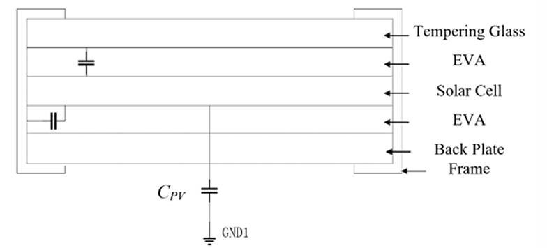 benefits have made non-isolated photovoltaic inverters a prominent direction in the development of photovoltaic systems. However, this configuration has notable drawbacks: the direct connection between the photovoltaic array and the inverter without electrical isolation from the AC grid leads to significant leakage current. This leakage current adversely affects power quality, increases system losses, reduces efficiency, and introduces safety risks. Therefore, addressing these issues and suppressing leakage current in non-isolated inverters is of great importance.
Over the past few decades, various methods have been developed to suppress leakage current in non-isolated photovoltaic inverters. The core approach is to minimize the amplitude and frequency of the common-mode voltage (CMV), which can be achieved through two main strategies: improving modulation techniques and enhancing circuit topology. Numerous circuit topology improvements have been proposed, such as adding electrical components like switches and capacitors to the AC or DC side, enabling the formation of freewheeling and clamp circuits. Modulation strategies, including space vector modulation and bipolar modulation, have also been explored, though they tend to be more complex.
This paper focuses on the improvement of circuit topologies. It begins with an analysis of leakage current models and then examines the latest leakage current suppression strategies for both single-phase and three-phase non-isolated photovoltaic inverters. The paper concludes by summarizing the issues associated with new types of photovoltaic inverters and offering suggestions for future research, providing valuable references for subsequent studies.
2.Leakage current of non-isolated photovoltaic inverters
Photovoltaic panels are the core components responsible for energy conversion in photovoltaic systems. These panels are composed of tempered glass, vinyl acetate, solar cells, and aluminum alloy frames. A notable characteristic of photovoltaic panels is the parasitic capacitance that exists between the panel frame and the ground. The structure of photovoltaic panels is illustrated in figure 1. The parasitic capacitance of photovoltaic panels is closely related to their size and shape. In practical applications, multiple panels are often connected in parallel, which increases the surface area of the photovoltaic array and, in turn, the parasitic capacitance. Photovoltaic panels made of crystalline silicon materials typically exhibit a parasitic capacitance of 100-200 pF, while the parasitic capacitance between a large-area photovoltaic array and the ground is approximately 50-150 nF/kW [4].
In non-isolated photovoltaic inverters, transformers are absent, which results in a lack of electrical isolation between the DC and AC sides. As a result, a certain parasitic capacitance exists between the photovoltaic array and the ground. A circuit can be formed between the DC side of the photovoltaic array, the AC side of the grid, the ground, and the parasitic capacitance within the photovoltaic system. Due to the high-frequency switching operation, the common-mode voltage may exhibit significant high-frequency and high-amplitude variations. This can excite the resonant circuit formed by the parasitic capacitance and inverter filter inductance, with the earth serving as the closed-loop path, ultimately generating a large leakage current.
|
(a) |
(b) |
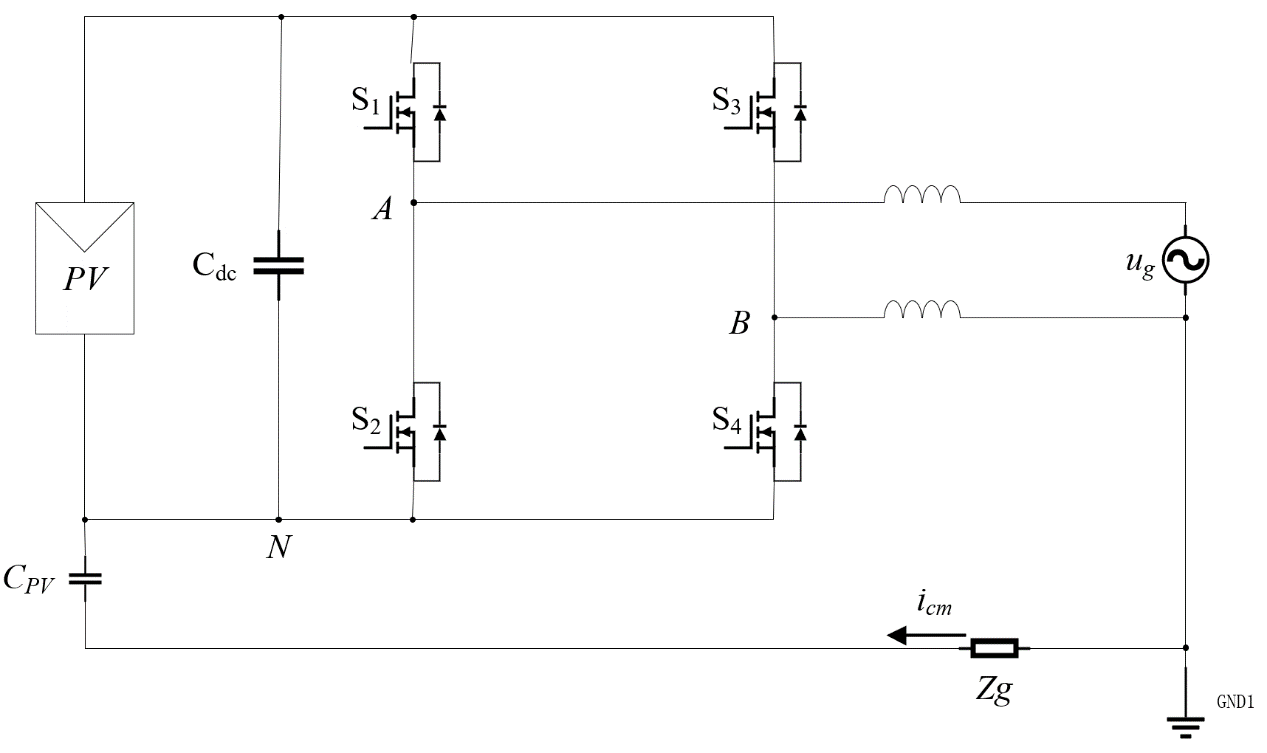
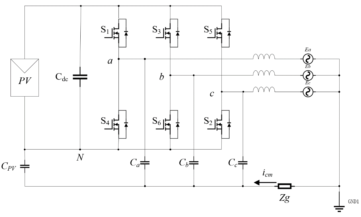
Figure 2: Inverter leakage current model. (a)Single-phase (b)Three-phase.
In a single-phase non-isolated full-bridge inverter, as shown in figure 2(a), CPV represents the parasitic capacitance between the photovoltaic panel and the ground, iCM is the system's common-mode leakage current, and Zg is the equivalent ground impedance between the grid grounding point and the inverter chassis grounding point [5]. The formulas for the common-mode voltage and leakage current are as follows:
|
\( {U_{CM}}=\frac{{U_{AN}}+{U_{BN}}}{2} \) |
(1) |
|
\( {i_{CM}}={C_{pv}}\frac{d{U_{CM}}}{dt} \) |
(2) |
In a three-phase non isolated inverter (as shown in figure 2(b)),\( {C_{a}} \),\( {C_{b}} \)and\( {C_{c}} \)are the parasitic capacitances of the inverter relative to the ground, respectively. The leakage current formula is the same as that of single-phase, and the common mode voltage formula is:
|
\( {U_{CM}}=\frac{{U_{AN}}+{U_{BN}}+{U_{CN}}}{3} \) |
(3) |
From the above formula, when CMV is a constant, the leakage current is zero.
3.Leakage current suppression strategies for non-isolated photovoltaic inverters based on topology improvement
The primary improvements in inverter topology focus on enhancing the common-mode characteristics and maintaining the stability of the common-mode voltage (CMV). Most improvement strategies involve adding additional switches and diodes to achieve these objectives. In the case of single-phase inverters, two novel designs were analyzed, both based on the modified topology of H-bridge inverters. For three-phase inverters, two designs were analyzed that improved upon traditional H6 inverters, along with one design that was developed by modifying the topology of three-phase cascaded H-bridge inverters.
3.1.Two freewheeling paths by adding flying capacitors
Figure 3: Proposed single-phase five-level transformer-less inverter.
Table 1: Switching states during positive period, Bridges voltages and CMVs.
|
State |
\( {U_{AN}} \) |
\( {U_{BN}} \) |
\( {U_{CM}} \) |
|
|
Powering |
A |
\( {U_{DC}} \) |
\( 0 \) |
\( \frac{{U_{DC}}}{2} \) |
|
B |
\( \frac{{3U_{DC}}}{4} \) |
\( \frac{{1U_{DC}}}{4} \) |
\( \frac{{U_{DC}}}{2} \) |
|
|
Freewheeling |
C |
\( \frac{{3U_{DC}}}{4} \) |
\( \frac{{1U_{DC}}}{4} \) |
\( \frac{{U_{DC}}}{2} \) |
|
D |
\( \frac{{U_{DC}}}{2} \) |
\( \frac{{U_{DC}}}{2} \) |
\( \frac{{U_{DC}}}{2} \) |
|
Zhu proposed a novel single-phase photovoltaic inverter [6]. The primary mechanism by which this topology reduces leakage current is through the addition of two flying capacitors, C1 and C2, along with eight additional switching transistors, compared to traditional single-phase full-bridge inverters. This design introduces two freewheeling circuits and maintains a constant common-mode voltage (CMV) by implementing an optimized switching transistor conduction strategy. The topology of the new single-phase five-level transformerless inverter is illustrated in figure 3.
This inverter structure operates in eight states: four powering states and four freewheeling states. During the positive cycle of the power grid, the voltage corresponding to each state is presented in table 1. According to the CMV calculation formula, the CMV in all states is maintained at\( \frac{{U_{DC}}}{2} \). The same principle applies during the negative cycle of the power grid. When the voltage across the capacitor terminals remains constant, the CMV also remains constant, thereby minimizing the leakage current to the greatest extent possible. It is important to note that, despite the use of two flying capacitors, their charging and discharging processes are always synchronized. This synchronization characteristic allows the reduction of voltage sensors to just one.
The modulation method employed in this inverter uses a reference waveform and four carrier signals to generate switching signals. This ensures that\( {U_{AU}} \),\( {U_{BN}} \)and\( {U_{CN}} \) have five voltage levels, while the CMV is maintained at\( \frac{{U_{DC}}}{2} \). Additionally, the voltage across the flying capacitors is limited to\( \frac{{U_{DC}}}{4} \) which lowers the performance requirements for the capacitors and significantly reduces the overall cost. Compared to traditional inverters, this design offers numerous advantages, including reduced leakage current, improved waveform quality, lower total losses, and fewer voltage sensor requirements.
3.2.AC decoupling with DC link midpoint clamping
A. O. Cunha Jr proposed a novel single-phase photovoltaic inverter [7]. Compared to traditional H-bridge inverters, this topology adds two switching transistors, S5 and S6, as well as two fast-recovery diodes, D3 and D4. The circuit topology is illustrated in figure 4. This design combines the benefits of AC decoupling technology and DC link midpoint clamping technology. It not only incorporates additional switching transistors on the AC side to fully isolate the freewheeling circuit from the conducting circuit, but also connects the voltage midpoint on the DC side to the AC side. This results in reduced leakage current and system losses compared to traditional H-bridge structures and H-bridge zero-voltage switching controlled rectifiers (HB-ZVSCRs).
|
|
|
|
|
Figure 4: Proposed Topology. |
Figure 5: Clamping Branch. |
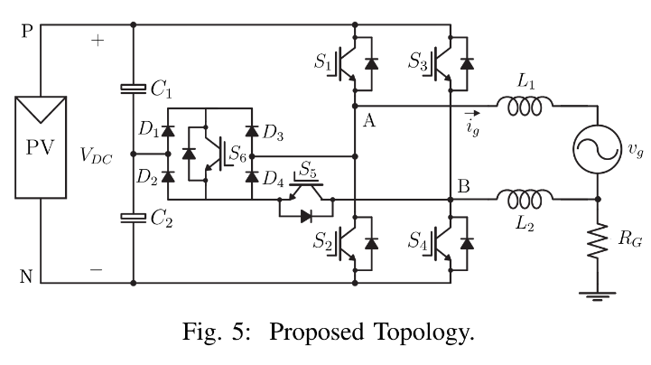
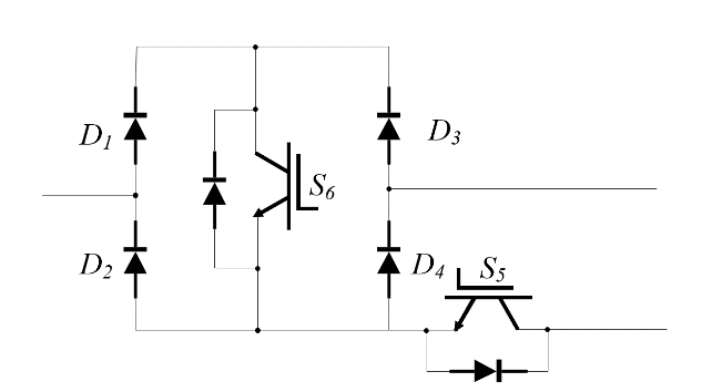
Table 2: Switching States, Bridges Voltages and CMVs.
|
State |
[\( {S_{1}} {S_{2}} {S_{3}} {S_{4}} {S_{5}} {S_{6}} \)] |
\( {U_{AN}} \) |
\( {U_{BN}} \) |
\( {U_{CM}} \) |
|
|
Conduction |
1 |
[1 0 0 1 0 0] |
\( {U_{DC}} \) |
0 |
\( \frac{{U_{DC}}}{2} \) |
|
Freewheeling |
2 |
[0 0 0 0 1 1] |
\( \frac{{U_{DC}}}{2} \) |
\( \frac{{U_{DC}}}{2} \) |
\( \frac{{U_{DC}}}{2} \) |
|
Conduction |
3 |
[0 1 1 0 0 0] |
\( {U_{DC}} \) |
0 |
\( \frac{{U_{DC}}}{2} \) |
|
Freewheeling |
4 |
[0 0 0 0 1 1] |
\( \frac{{U_{DC}}}{2} \) |
\( \frac{{U_{DC}}}{2} \) |
\( \frac{{U_{DC}}}{2} \) |
The primary method for suppressing leakage current in this topology is by maintaining a constant common-mode voltage (CMV). This structure operates in four distinct modes, with the switch states and CMV values outlined in table 2. A key advantage of this design is that during the freewheeling cycle, fewer semiconductor components conduct current compared to traditional configurations. In Mode 2, for example, the circuit consists of only one switch and one diode, while in Mode 4, it involves only one switch and two diodes. This characteristic enhances the overall efficiency of the topology. Additionally, the presence of clamping branches (as shown in figure 5) ensures that the CMV is clamped at\( \frac{{U_{DC}}}{2} \)across all operating modes, thereby effectively suppressing leakage current.
This inverter utilizes a sinusoidal reference signal compared against two triangular carriers, which is referred to as the level conversion pulse-width modulation (PWM) method. This approach is simpler and more user-friendly compared to other modulation methods.
3.3.Embedding auxiliary switches into the bridge
Guo proposed a novel strategy for suppressing leakage current [8]. Unlike other improvement strategies, such as adding flying capacitors, this approach embeds switching elements directly into the inverter bridge and introduces six additional auxiliary switches, as shown in figure 6(a) and 6(b). Although the topological structures differ, they share similar electrical characteristics. Taking phase, A as an example, this inverter operates in three distinct states, with the details of each operating mode shown in table 3. The behavior of phase B and phase C can be inferred similarly, following the same principles:
|
\( \begin{array}{c} {U_{AN}}=(\frac{{U_{DC}}}{2})×{S_{A}} \\ {U_{BN}}=(\frac{{U_{DC}}}{2})×{S_{B}} \\ {U_{CN}}=(\frac{{U_{DC}}}{2})×{S_{C}} \end{array} \) |
(4) |
Combining the CMV formula of a three-phase inverter, the relationship between CMV and switch state can be obtained as follows:
|
\( {U_{CM}}=\frac{{U_{DC}}}{6}×({S_{A}}{+S_{B}}{+S_{C}}) \) |
(5) |
|
|
|
|
|
(a) |
(b) |
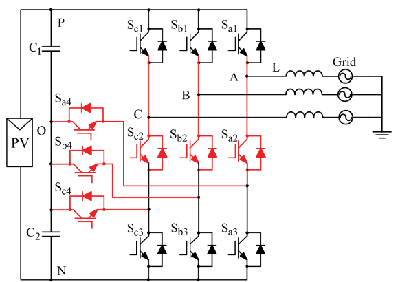
Figure 6: Proposed Topology (a)ESI-1 (b)ESI-2.
Table 3: Switching States and CMVs.
|
State |
[S1 S2 S3 S4] |
\( {S_{A}} \) |
\( {U_{AN}} \) |
|
2 |
[1 0 0 0] |
2 |
\( {U_{DC}} \) |
|
1 |
[0 1 0 1] |
1 |
\( \frac{{U_{DC}}}{2} \) |
|
0 |
[0 1 1 0] |
0 |
0 |
From the equation above, the common-mode voltage (CMV) is solely dependent on the states of the ABC three phases. As long as the sum of\( {S_{A}}{+S_{B}}{+S_{C}} \) remains constant, the CMV can be maintained at a stable value, effectively suppressing leakage current. The modulation method employed in this inverter is conventional dual-carrier modulation, which is relatively straightforward. Despite the addition of more switching devices, the leakage current can still be effectively reduced to well below 300 mA, resulting in lower power losses and improved power quality. Furthermore, the elimination of costly electromagnetic interference (EMI) filters contributes to a reduction in the overall cost of photovoltaic systems.
3.4.Modify the continuation path to make CMV constant
Chamarthi P. K. proposed an improved inverter based on the three-phase cascaded H-bridge (CHB) [9]. In the traditional CHB design, when the inverter operates in a specific state, the common-mode voltage (CMV) synthesized from the three phases is\( 3{U_{DC}} \). When it operates in the switching state, the CMV synthesized by the three phases becomes\( 2{U_{DC}} \), indicating that the CMV in traditional CHB designs is variable, which contributes to the generation of leakage current [10]. However, in the improved CHB design described in this paper (as shown in figure 7), the issue of leakage current in traditional CHB inverters has been mitigated by adding two new switches to each phase: S5 between the bridges of each phase, and S6 on the new branch. These two switching devices ensure that the CMV for each phase, during both freewheeling and switching states, is maintained at\( \frac{{U_{DC}}}{2} \), and the CMV synthesized by the three phases is\( \frac{{3U_{DC}}}{2} \). This allows the CMV to remain constant, effectively suppressing leakage current.
3.5.Adding clamp branch
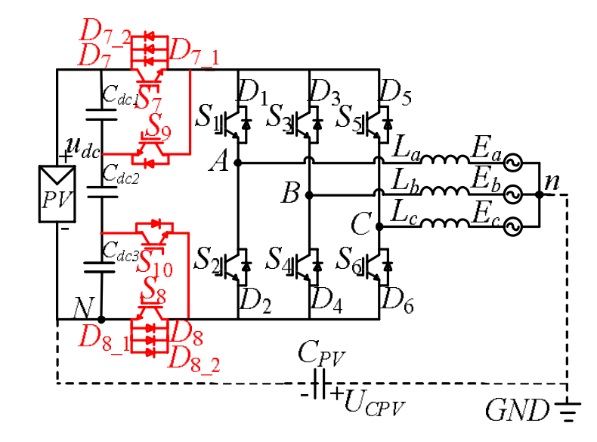
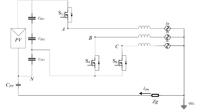
Jiang L proposed a DCC-H10 inverter topology [11] (as shown in figure 8), which can maintain the CMV of the inverter at\( \frac{{U_{DC}}}{2} \)under reasonable modulation strategies, thereby suppressing common mode leakage current. Based on the traditional H6 inverter, a forward clamp branch is added, which is the key to keeping CMV constant, including three capacitors with capacitance values that satisfy the ratio of\( {C_{DC1}}:{C_{DC2}}:{C_{DC3}}=2:1:2 \)and two switches S9 and S10.
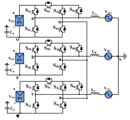
Figure 7: Proposed Topology.
This transformer has 8 operating states, taking operating mode 1 as an example (as shown in figure 9). In Mode 1 state, the voltage on the upper side of the circuit\( {U_{AN}} \)is\( {U_{DC}} \). Due to the presence of the clamp circuit, the voltage on the lower side of the circuit\( {U_{BN}} \)is\( {U_{CN}} \). They are the same as the voltage at the\( {C_{DC3}} \)and they are both\( \frac{{U_{DC}}}{4} \). According to the CMV formula, we can deduce that\( {U_{CM}}=\frac{(\frac{{U_{DC}}+{U_{DC}}}{4+}\frac{{U_{DC}}}{4})}{3}=\frac{{U_{DC}}}{2} \). In other states, the same applies, and finally it is deducted that in all operating states, CMV is\( \frac{{U_{DC}}}{2} \). At the same time, this inverter also has a topology that uses 9 switching tubes, replacing the clamp switch S9 or S10 with a diode. This type of inverter has one less state compared to the DCC-H10 inverter, but it can still maintain a constant CMV to suppress leakage current, with fewer switching transistors and lower system losses. In the case of using model prefabricated control strategies, single zero vector modulation has been achieved, and this can make the modulation process simpler.
4.Results and Future
This article analyzes several new leakage current suppression strategies for single-phase and three-phase non-isolated photovoltaic inverters aimed at improving circuit topology, and identifies the following issues:
Some improvement strategies fail to consider the issues of voltage and heat balance. As noted in reference [8], the number of switches in the upper and lower parts of the inverter bridge is often inconsistent. Given that the model and parameters of the switches in the inverter bridge are typically the same, this results in an unbalanced voltage distribution, with some switches bearing significantly higher voltage than others. Under low-voltage conditions, this may have a limited impact, but as the capacity of photovoltaic systems increases, the stability and lifespan of the switches will be severely challenged under high-power, high-voltage operation. This increases the complexity of switch selection and leads to higher costs and potential safety risks. The H9 circuit topology mentioned in reference [11] exhibits similar problems, where the asymmetrical structure of the DC side causes uneven heating in different parts of the inverter. This results in varying temperatures across the system, affecting the lifespan of electrical components and increasing maintenance costs.
|
|
|
|
|
Figure 8: Proposed Topology. |
Figure 9: Schematic diagrams of Mode 1. |
The operating modes and control strategies of some inverters are overly complex. While improvements in circuit topology require matching modulation strategies, excessive switching transistors or asymmetrical circuit designs complicate these strategies. For example, the inverter discussed in reference [12] has 27 operating states, requiring more switching devices and highly complex modulation methods and control modes. Similarly, while the clamping branch in reference [7] maintains constant CMV, its complex and relatively independent operating mode makes practical application more challenging.
Significant changes to the topology or adding a large number of semiconductor devices can lead to several problems. For instance, the topology proposed in reference [11] adds four switching transistors and eight diodes, increasing both inverter losses and the cost and size of the system. Although reference [8] claims that such improvements can reduce the total cost of photovoltaic systems by eliminating expensive filters and improving power quality, this remains to be verified in practical applications. Moreover, adding more semiconductor devices may also lead to more complex control methods and additional control devices.
As the demand for renewable energy continues to rise, the capacity of photovoltaic systems will increase accordingly. This will also drive demand for photovoltaic inverters. In the development of non-isolated photovoltaic inverters, leakage current suppression remains a key focus, with future improvements aimed at achieving higher efficiency, greater power density, improved power quality, and reduced cost and size. In the context of existing topology-based leakage current suppression strategies, several potential improvement methods are proposed:
When designing the topology of photovoltaic inverter circuits, the problem of uneven voltage and heating caused by uneven distribution of switches should be considered. For example, adding additional electrical components at symmetrical positions to balance voltage distribution, such as in the topology mentioned in reference [8], can be achieved by adding a symmetrical number of switching transistors on both the upper and lower sides of the bridge, making voltage distribution more uniform and extending switch service life. However, as mentioned earlier, more switching transistors will result in greater losses and more complex operating modes, and its cost still needs to be evaluated in practical use.
The adoption of more advanced semiconductor devices and operating techniques can significantly benefit inverter performance. Most current inverters operate in a hard-switching mode, which results in greater losses and reduced efficiency. Implementing soft-switching techniques, such as Zero Voltage Switching (ZVS) and Zero Current Switching (ZCS), will increase the operating frequency of inverters, thereby improving reliability and efficiency [13]. As for capacitors, the increasing voltage and power levels in future photovoltaic systems will require higher quality components, such as split capacitors and flying capacitors. Many existing capacitors do not meet the stringent requirements of photovoltaic inverters, especially in terms of temperature sensitivity and short lifespans at high frequencies. Therefore, companies need to develop higher-quality capacitors that are compatible with photovoltaic inverters. These improvements will result in higher efficiency and longer service life for photovoltaic inverters.
Most current leakage current models focus primarily on the influence of common-mode voltage generated by the DC side, while neglecting the impact of the AC grid at high frequencies. Developing a more comprehensive leakage current model that includes the influence of the AC grid will improve the accuracy of leakage current calculations and contribute to the development of more effective suppression strategies.
5.Conclusion
This article presents a leakage current model for non-isolated photovoltaic inverters and analyzes its causes and influencing factors. Several latest leakage current suppression strategies based on improved topology structures are analyzed, most of which improve the existing inverter topology by adding freewheeling circuits and midpoint clamp circuits to maintain a constant CMV, which has a very good effect on suppressing leakage current. On this basis, this article also analyzes the problems and possible solutions of existing strategies, providing reference for future research.
References
[1]. Singh, G. K. (2013). Solar power generation by PV (photovoltaic) technology: A review. Energy, 53, 1-13.
[2]. Dogga, R., & Pathak, M. K. (2019). Recent trends in solar PV inverter topologies. Solar Energy, 183, 57-73.
[3]. S Jahan, SP Biswas, MK Hosain, MR Islam, MM Rahman, Y Guo (2021). A new control scheme for three-phase non-isolated grid feeding PV inverter. In Proceedings of the 2021 31st Australasian Universities Power Engineering Conference (AUPEC) (pp. 1-6).
[4]. Myrzik, J. M. A., & Calais, M. (2003). String and module integrated inverters for single-phase grid connected photovoltaic systems - a review. In Proceedings of the 2003 IEEE Bologna Power Tech Conference, Bologna, Italy (Vol. 2, pp. 1-8).
[5]. E Gubia, P Sanchis, A Ursua, J Lopez, L Marroyo (2007). Ground currents in single-phase transformerless photovoltaic systems. Progress in Photovoltaics: Research and Applications, 15(7), 629-650.
[6]. Zhu, X., Wang, H., Zhang, W., Wang, H., Deng, X., & Yue, X. (2022). A single-phase five-level transformer-less PV inverter for leakage current reduction. IEEE Transactions on Industrial Electronics, 69(4), 3546-3555.
[7]. Cunha, A. O., Bahia, F. A. C., Méllo, J. P. R. A., Tahim, A. P. N., & Costa, F. F. (2022). A novel single-phase transformerless grid-connected PV inverter. In Proceedings of the 2022 IEEE Energy Conversion Congress and Exposition (ECCE), Detroit, MI, USA (pp. 1-7).
[8]. Guo, X., Yang, Y., & Zhu, T. (2017). ESI: A novel three-phase inverter with leakage current attenuation for transformerless PV systems. IEEE Transactions on Industrial Electronics, 65(4), 2967-2974.
[9]. PK Chamarthi, A Al-Durra, THM El-Fouly, K Al Jaafari (2021). A novel three-phase transformerless cascaded multilevel inverter topology for grid-connected solar PV applications. IEEE Transactions on Industry Applications, 57(3), 2285-2297.
[10]. Sridhar, V., & Umashankar, S. (2017). A comprehensive review on CHB MLI based PV inverter and feasibility study of CHB MLI based PV-STATCOM. Renewable and Sustainable Energy Reviews, 78, 138-156.
[11]. L Jiang, F Dai, Y Zeng, H Wu (2023). A three-phase transformerless photovoltaic grid-connected inverter with reduced leakage current. In Proceedings of the 2023 4th International Conference on Smart Grid and Energy Engineering (SGEE) (pp. 274-278).
[12]. M Lak, YT Tsai, BR Chuang, TL Lee, MH Moradi (2021). A hybrid method to eliminate leakage current and balance neutral point voltage for photovoltaic three-level T-type inverter. IEEE Transactions on Power Electronics, 36(10), 12070-12089.
[13]. Xiao, H. F., Liu, X. P., & Lan, K. (2014). Zero-voltage-transition full-bridge topologies for transformerless photovoltaic grid-connected inverter. IEEE Transactions on Industrial Electronics, 61(10), 5393-5401.
Cite this article
Ye,Q. (2025). Leakage Current Suppression Strategies for Non-Isolated Photovoltaic Inverters: Topology Improvements and Performance Analysis. Applied and Computational Engineering,127,106-115.
Data availability
The datasets used and/or analyzed during the current study will be available from the authors upon reasonable request.
Disclaimer/Publisher's Note
The statements, opinions and data contained in all publications are solely those of the individual author(s) and contributor(s) and not of EWA Publishing and/or the editor(s). EWA Publishing and/or the editor(s) disclaim responsibility for any injury to people or property resulting from any ideas, methods, instructions or products referred to in the content.
About volume
Volume title: Proceedings of the 5th International Conference on Materials Chemistry and Environmental Engineering
© 2024 by the author(s). Licensee EWA Publishing, Oxford, UK. This article is an open access article distributed under the terms and
conditions of the Creative Commons Attribution (CC BY) license. Authors who
publish this series agree to the following terms:
1. Authors retain copyright and grant the series right of first publication with the work simultaneously licensed under a Creative Commons
Attribution License that allows others to share the work with an acknowledgment of the work's authorship and initial publication in this
series.
2. Authors are able to enter into separate, additional contractual arrangements for the non-exclusive distribution of the series's published
version of the work (e.g., post it to an institutional repository or publish it in a book), with an acknowledgment of its initial
publication in this series.
3. Authors are permitted and encouraged to post their work online (e.g., in institutional repositories or on their website) prior to and
during the submission process, as it can lead to productive exchanges, as well as earlier and greater citation of published work (See
Open access policy for details).
References
[1]. Singh, G. K. (2013). Solar power generation by PV (photovoltaic) technology: A review. Energy, 53, 1-13.
[2]. Dogga, R., & Pathak, M. K. (2019). Recent trends in solar PV inverter topologies. Solar Energy, 183, 57-73.
[3]. S Jahan, SP Biswas, MK Hosain, MR Islam, MM Rahman, Y Guo (2021). A new control scheme for three-phase non-isolated grid feeding PV inverter. In Proceedings of the 2021 31st Australasian Universities Power Engineering Conference (AUPEC) (pp. 1-6).
[4]. Myrzik, J. M. A., & Calais, M. (2003). String and module integrated inverters for single-phase grid connected photovoltaic systems - a review. In Proceedings of the 2003 IEEE Bologna Power Tech Conference, Bologna, Italy (Vol. 2, pp. 1-8).
[5]. E Gubia, P Sanchis, A Ursua, J Lopez, L Marroyo (2007). Ground currents in single-phase transformerless photovoltaic systems. Progress in Photovoltaics: Research and Applications, 15(7), 629-650.
[6]. Zhu, X., Wang, H., Zhang, W., Wang, H., Deng, X., & Yue, X. (2022). A single-phase five-level transformer-less PV inverter for leakage current reduction. IEEE Transactions on Industrial Electronics, 69(4), 3546-3555.
[7]. Cunha, A. O., Bahia, F. A. C., Méllo, J. P. R. A., Tahim, A. P. N., & Costa, F. F. (2022). A novel single-phase transformerless grid-connected PV inverter. In Proceedings of the 2022 IEEE Energy Conversion Congress and Exposition (ECCE), Detroit, MI, USA (pp. 1-7).
[8]. Guo, X., Yang, Y., & Zhu, T. (2017). ESI: A novel three-phase inverter with leakage current attenuation for transformerless PV systems. IEEE Transactions on Industrial Electronics, 65(4), 2967-2974.
[9]. PK Chamarthi, A Al-Durra, THM El-Fouly, K Al Jaafari (2021). A novel three-phase transformerless cascaded multilevel inverter topology for grid-connected solar PV applications. IEEE Transactions on Industry Applications, 57(3), 2285-2297.
[10]. Sridhar, V., & Umashankar, S. (2017). A comprehensive review on CHB MLI based PV inverter and feasibility study of CHB MLI based PV-STATCOM. Renewable and Sustainable Energy Reviews, 78, 138-156.
[11]. L Jiang, F Dai, Y Zeng, H Wu (2023). A three-phase transformerless photovoltaic grid-connected inverter with reduced leakage current. In Proceedings of the 2023 4th International Conference on Smart Grid and Energy Engineering (SGEE) (pp. 274-278).
[12]. M Lak, YT Tsai, BR Chuang, TL Lee, MH Moradi (2021). A hybrid method to eliminate leakage current and balance neutral point voltage for photovoltaic three-level T-type inverter. IEEE Transactions on Power Electronics, 36(10), 12070-12089.
[13]. Xiao, H. F., Liu, X. P., & Lan, K. (2014). Zero-voltage-transition full-bridge topologies for transformerless photovoltaic grid-connected inverter. IEEE Transactions on Industrial Electronics, 61(10), 5393-5401.