


1. Introduction
1.1. Research Background and Significance
In recent years, confronted with the constantly expanding energy demand and deteriorating environmental issues, the development of Electric Vehicles (EVs) has been vigorously supported. The Inductive Wireless Power Transfer (WPT) system, by means of magnetic coupling, transmits power through the air gap in a non-physical contact manner, achieving the flow of energy between systems. Compared with wired transmission, wireless power transfer enjoys more advantages in terms of safety, reliability and convenience, and is widely applied in fields such as electronic devices, biomedicine, electric vehicles, underwater equipment, etc. [1-3]. The Bidirectional Wireless Power Transfer (BWPT) system is capable of realizing bidirectional energy transmission between the power grid and equipment, effectively mitigating the influence of various electricity load fluctuations on the power grid, and playing a significant role in achieving a strong and intelligent power grid [4-5]. It has drawn increasing attention in the Vehicle to Grid (V2G) system [6-9].
The BWPT system for electric vehicles confronts numerous challenges during the design and implementation processes, specifically encompassing: while the system possesses the capacity for bidirectional energy transfer, it is necessary to satisfy the charging and discharging requirements of various types of batteries at different states of charge and overcome the influence of parameter drift caused by positional offsets between the vehicle end and the ground end. Simultaneously, it is essential to strike a balance between efficiency and power density. Moreover, the system needs to reduce reliance on real-time wireless communication and overcome the impact of electromagnetic energy on wireless communication receiving devices.
1.2. Current Research Status at Home and Abroad
At present, certain achievements have been made in the research on the architecture and control methods of bidirectional wireless charging and discharging systems for electric vehicles.
Regarding the system architecture, the wireless bidirectional charging and discharging system for electric vehicles needs to be more flexible in architecture selection to adapt to bidirectional and wide-offset operation conditions. Literature [10] proposed a complete 20 kW BWPT system with a two-stage architecture and completed the initial test. The full-load efficiency of the system could reach 92.7%, but the test results under the wide-range offset condition of the coil were not provided. Literature [11] proposed a push-pull parallel resonant BWPT system architecture based on the integration of DD coils. In this architecture, the introduction of the magnetically integrated coil not only enhanced the power density of the system but also significantly reduced the losses caused by magnetic components. However, due to the mutual constraints among output power, coil offset, and zero voltage switching (ZVS) operating region, and the non-monotonic change pattern, it has a significant impact on the realization of the system's closed-loop control.
In terms of control methods, the common control methods used in bidirectional radio frequency power transmission systems at present mainly include amplitude modulation, pulse frequency modulation, phase modulation, and pulse density modulation. Papers [12-13] proposed a double phase modulation strategy by adjusting the phase angle of the primary and secondary sides to change the output voltage, achieving controllable output power, but this strategy cannot achieve wide range ZVS, and the switching loss is large, resulting in a low overall efficiency. Paper [14] proposed a harmonic asymmetric pulse width modulation, which satisfies the low power output of the system in light load condition and achieves ZVS, but no consideration was given to the power regulation in heavy load condition.
1.3. Research Content and Chapter Arrangement
This paper, on the basis of summarizing the current domestic and international research and applications at the present stage, will propose an efficient wireless bidirectional charging and discharging system for electric vehicles of WPT2 level based on the LCC-S compensation network. The main content and chapter arrangement of this paper are as follows: Section 2 mainly expounds the relevant theories of the LCC-S high-frequency compensation topology and the three-level wireless bidirectional charging and discharging system for electric vehicles, laying a theoretical foundation for the proposal in this paper; Section 3, based on the theory in Section 2, proposes an architecture of the wireless bidirectional charging and discharging system for electric vehicles and the corresponding control method; Section 4 mainly conducts the effect verification of the system proposed in Section 3 using the experimental platform; Section 5 is the summary of the full text.
2. Related Theories
2.1. Analysis of the LCC-S High-Frequency Resonant Network
The reactive power compensation capacity of the high-frequency resonant network can be characterized by its input impedance. The input impedance and transmission characteristics of the LCC-S high-frequency resonant network topology are as follows.
The circuit principle of LCC-S is depicted in Figure 1. Among them, the self-inductances of the primary and secondary coils are \( {L_{1}} \) and \( {L_{2}} \) respectively, the mutual inductance (MI) between the primary and secondary coils is \( M \) , the primary compensation inductance is \( {L_{f1}} \) , the primary compensation capacitances are \( {C_{f1}} \) and \( {C_{1}} \) , the secondary compensation capacitance is \( {C_{2}} \) , and the switching frequency of the bridge arm is \( f \) .

Figure 1: Schematic Diagram of LCC-S Circuit.
The equivalent circuit of the LCC-S network when it forwards energy using the MI model is depicted in Figure 2.
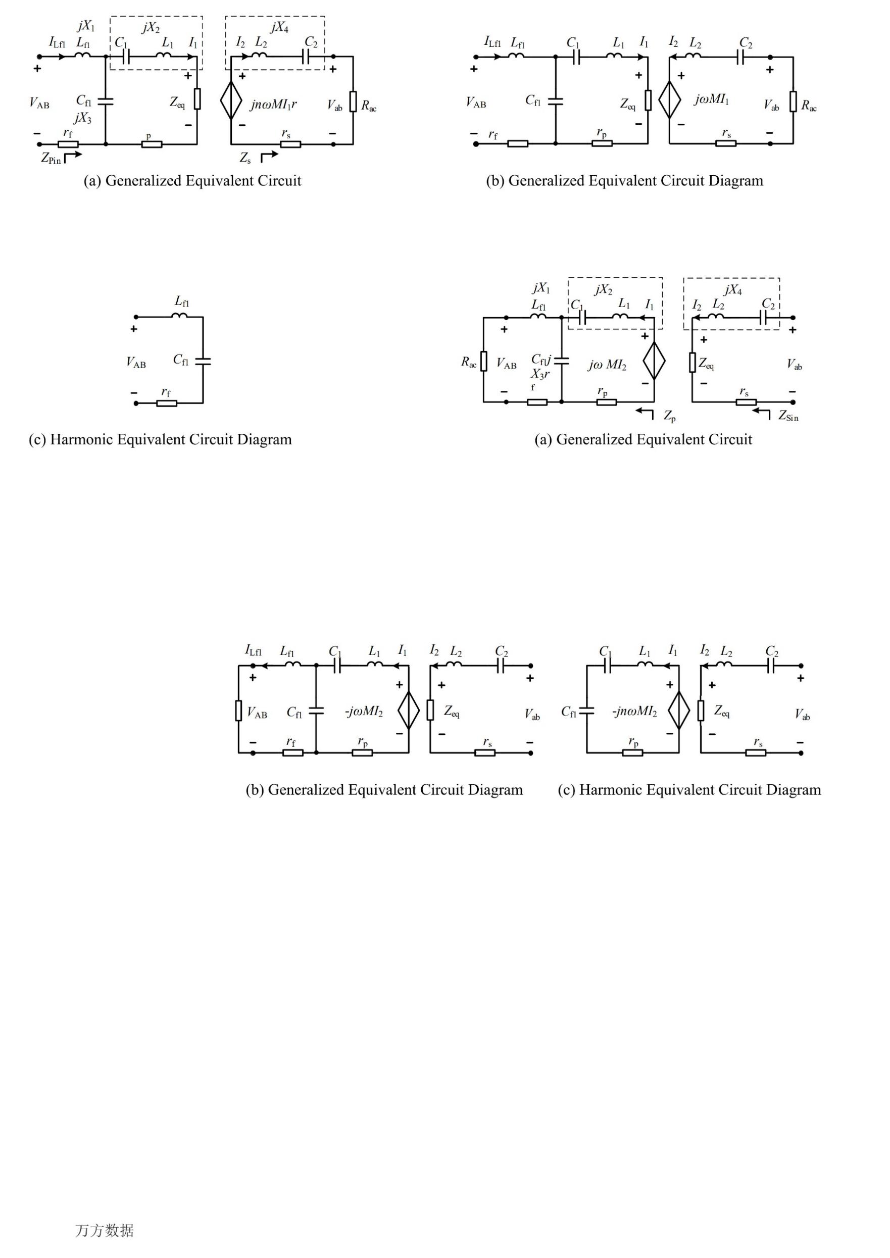
Figure 2: The equivalent circuit of LCC-S in forward operation.
Based on the MI model, the impedance mapped from the secondary side of the system to the primary side can be derived as
\( {Z_{eq}}=\frac{{n^{2}}{ω^{2}}{M^{2}}}{{Z_{s}}}=\frac{{n^{2}}{ω^{2}}{M^{2}}{R_{ac}}}{R_{ac}^{2}+X_{4}^{2}}-j\frac{{n^{2}}{ω^{2}}{M^{2}}{X_{4}}}{R_{ac}^{2}+X_{4}^{2}} \) (1)
Thereby, the input impedance of the general equivalent circuit is obtained
\( {Z_{pin}}=\frac{X_{3}^{2}{Z_{eq}}}{{({X_{2}}+{X_{3}})^{2}}+Z_{eq}^{2}}+j\frac{({X_{1}}{X_{2}}+{X_{1}}{X_{3}}+{X_{2}}{X_{3}})({X_{2}}+{X_{3}})+Z_{eq}^{2}({X_{1}}+{X_{3}})}{{({X_{2}}+{X_{3}})^{2}}+Z_{eq}^{2}} \) (2)
When configuring the parameters of the compensation network on the secondary side, only the fundamental wave effect ( \( n=1,ω={ω_{0}} \) ) is taken into account. This causes the secondary side compensation capacitor \( {C_{2}} \) to resonate in series with the coil self-inductance \( {L_{2}} \) , and the AC impedance on the secondary side becomes zero. The LCC resonant network on the primary side is designed in a symmetrical T-type, with \( {X_{1}}+{X_{3}}{=X_{2}}+{X_{3}}=0 \) . Thus, the imaginary part of \( {Z_{pin}} \) is zero, achieving a zero input impedance angle at the fundamental wave. The curves showing the variation of the magnitude and phase of the input impedance with frequency under different loads are presented in Figure 3 as follows.
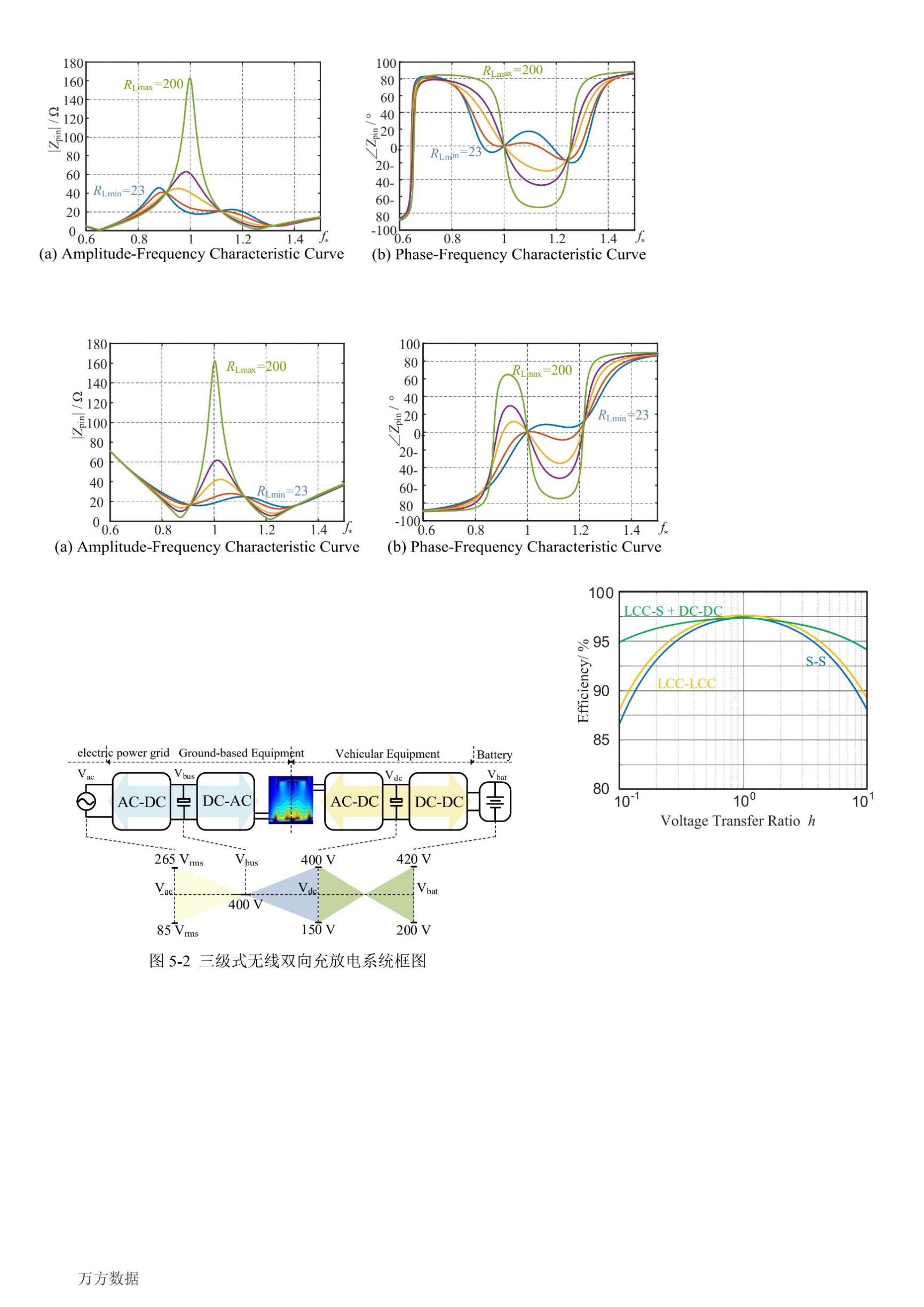
Figure 3: The curve of the magnitude and phase of the input impedance for positive energy transmission varying with frequency (k = 0.323).
The system voltage gain \( {g_{v}} \) is only related to the MI between the transmit and receive coils M and the primary compensation inductance \( {L_{f1}} \) , and the expression is as follows
\( {g_{v}}=\frac{{V_{AB}}}{{V_{ab}}}=\frac{M}{{L_{f1}}} \) (3)
By the same token, the equivalent circuit of the LCC-S network during reverse energy transmission can be obtained, as shown in Figure 4.

Figure 4: The equivalent circuit of LCC-S in reverse operation.
Likewise, the equivalent impedance \( {Z_{p}} \) at the receiving end during reverse operation can be deduced.
\( {Z_{p}}=\frac{{R_{ac}}X_{3}^{2}}{R_{ac}^{2}+{({X_{1}}+{X_{3}})^{2}}}+j\frac{R_{ac}^{2}{({X_{2}}+{X_{3}})^{2}}+({X_{1}}+{X_{3}})({X_{1}}{X_{2}}{+X_{1}}{X_{3}}+{X_{2}}{X_{3}})}{R_{ac}^{2}+{({X_{1}}+{X_{3}})^{2}}} \) (4)
Furthermore, the expression of the equivalent input impedance of the resonant network at the transmitting end during reverse operation can be deduced.
\( {Z_{ins}}={Z_{eq}}+j{X_{4}}=\frac{{ω^{2}}{M^{2}}}{{Z_{p}}}+j{X_{4}} \) (5)
The principle of parameter configuration for the compensation network during forward energy transfer is the same as that during reverse energy transfer. When \( n=1 \) and \( ω={ω_{0}} \) , by setting \( {X_{4}}={X_{1}}+{X_{3}}{=X_{2}}+{X_{3}}=0 \) , the variation trends of the amplitude and phase angle of the equivalent input impedance of the LCC-S type compensation topology during reverse energy transfer with the operating frequency can be plotted as shown in Figure 5.
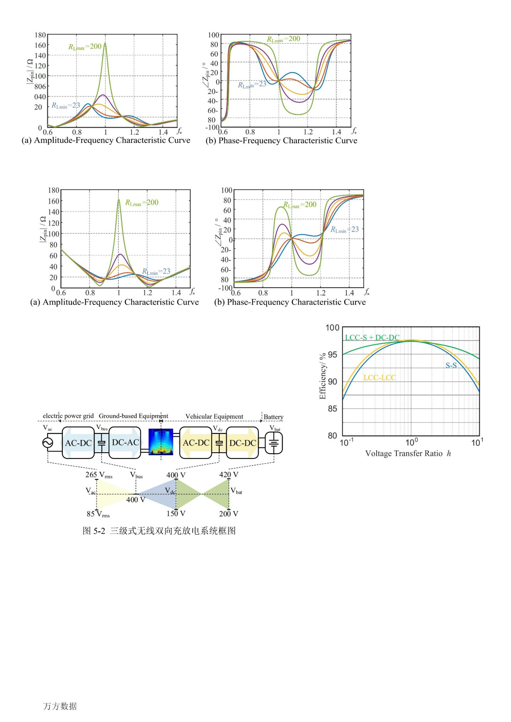
Figure 5: The curves of the magnitude and phase of the input impedance versus frequency during reverse energy transmission (k = 0.323).
The system voltage gain \( {g_{v}} \) is only related to the mutual inductance between the transmit and receive coils M and the primary compensation inductance \( {L_{f1}} \) , and the expression is as follows
\( {g_{v}}=\frac{{V_{ab}}}{{V_{AB}}}=\frac{{L_{f1}}}{M} \) (6)
The active and reactive powers transmitted by the system are respectively
\( \begin{cases} \begin{array}{c} P=-\frac{{V_{ab}}({ω^{2}}M{L_{f1}}{V_{AB}}cos{α}-{ω^{2}}{{L_{f1}}^{2}}{V_{ab}}-{V_{ab}}{r_{p}}{r_{f}})}{{ω^{2}}{M^{2}}{r_{f}}+{ω^{2}}{L_{f1}}{r_{s}}+{r_{p}}{r_{s}}{r_{f}}} \\ Q=-\frac{{ω^{2}}M{L_{f1}}{V_{ab}}{V_{AB}}sin{α}}{{ω^{2}}{M^{2}}{r_{f}}+{ω^{2}}{L_{f1}}{r_{s}}+{r_{p}}{r_{s}}{r_{f}}} \end{array} \end{cases} \) (7)
The circuit parameters of WPT2 grade are selected to plot the variation curve of the system transmission power with the external phase shift angle as shown in Figure 6.
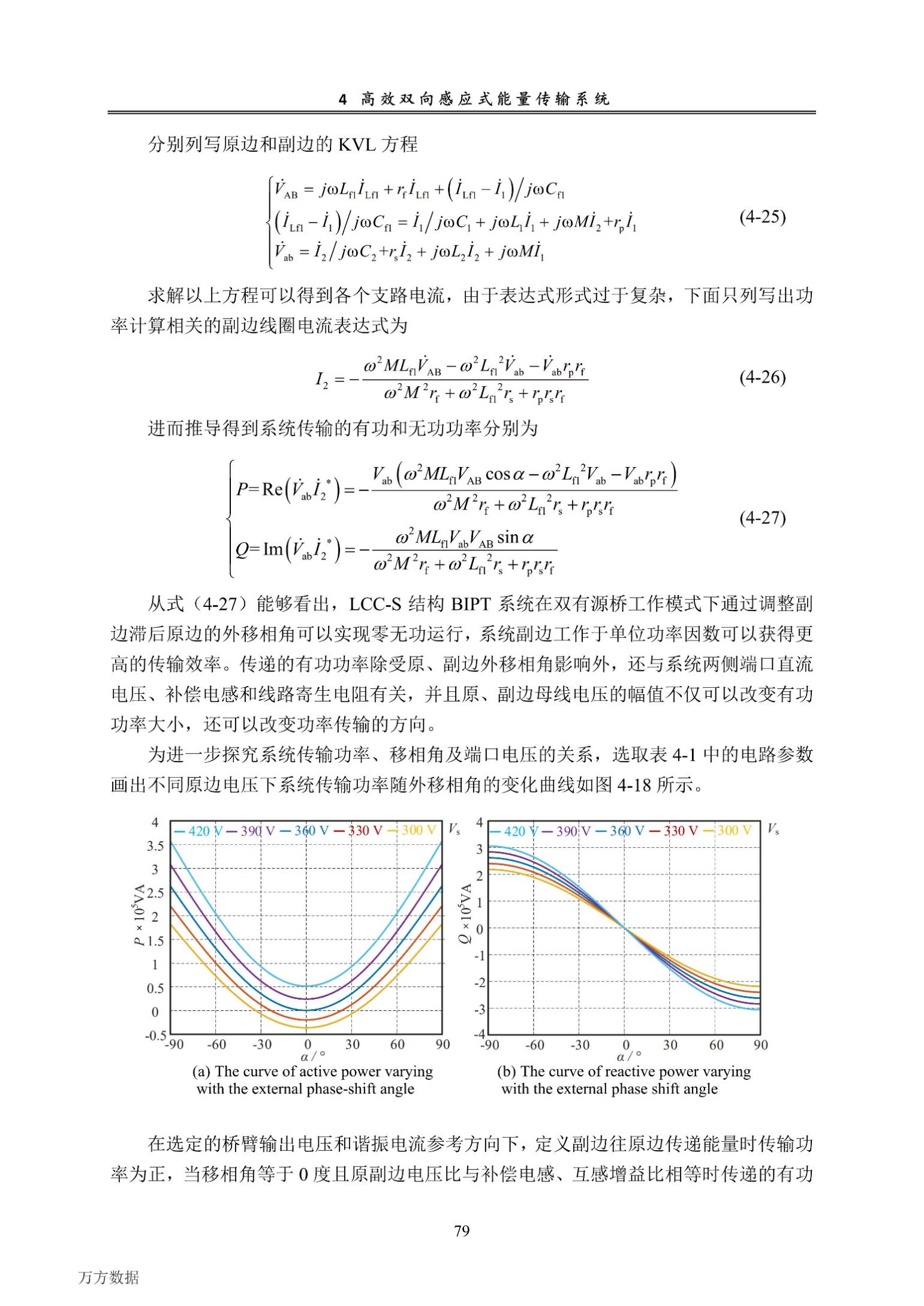
Figure 6: The variation curve of the system transmission power with the external phase shift angle.
2.2. Analysis of the Three-Stage Wireless Bidirectional Charging and Discharging System
In the three-level wireless bidirectional charging and discharging topological structure, the matching of the IPT output voltage with the load is achieved by adding a bidirectional buck-boost converter, which overcomes the impact brought by an excessive offset range and ensures that the BWPT link always operates at the optimal voltage transfer ratio. The system block diagram is presented in Figure 7.
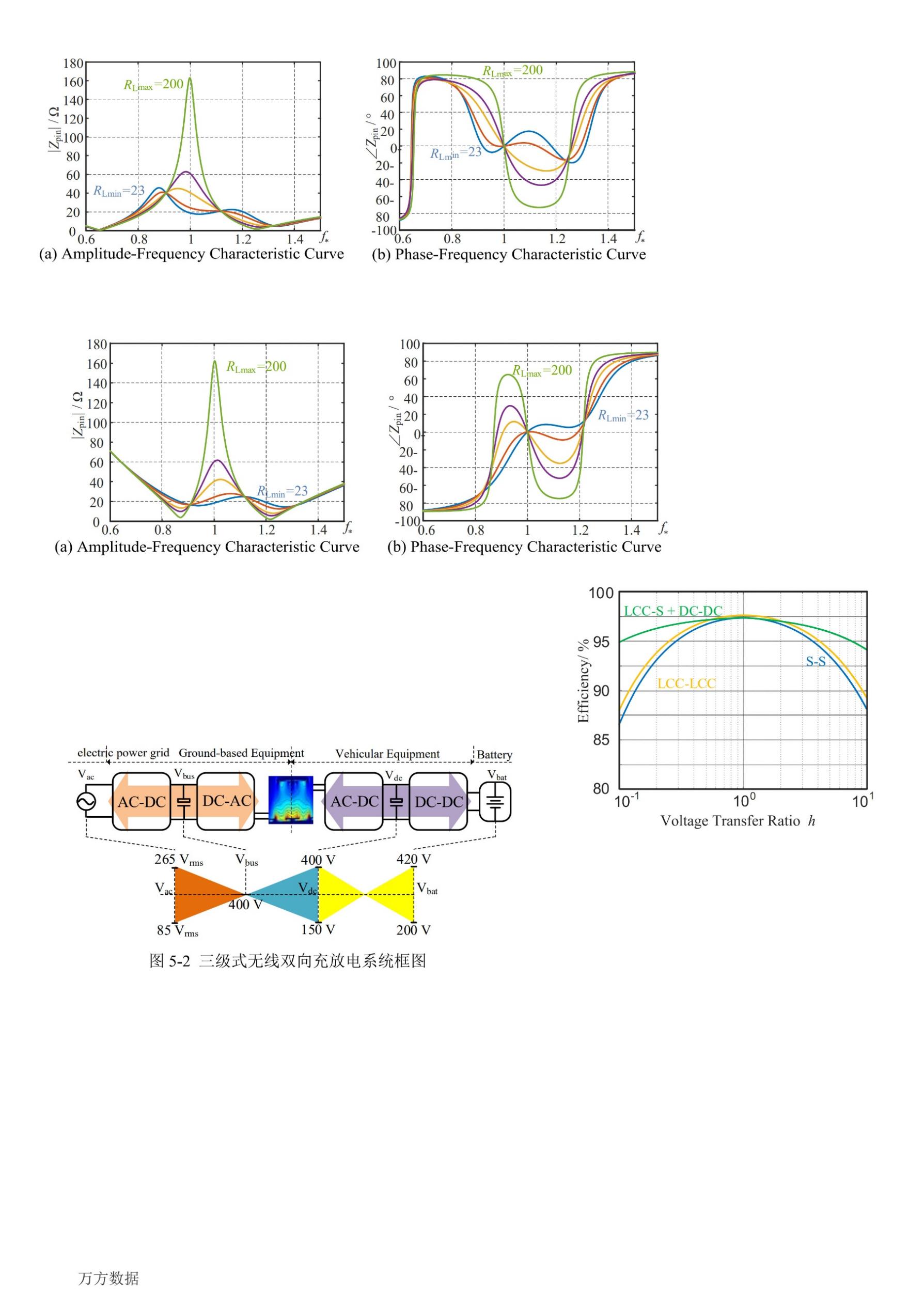
Figure 7: The block diagram of the three-stage wireless bidirectional charging and discharging system.
When efficiency modeling of the bidirectional DC-DC converter is conducted, the classic hard-switching half-bridge Buck-Boost converter model is adopted. Under the given input voltage \( {V_{in}} \) , output voltage \( {V_{out}} \) , and load power \( {P_{o}} \) , disregarding the influence of inductor current ripple, as the two switching tubes are synchronously turned on and the freewheeling loss during the dead time is ignored, its conduction loss can be obtained as
\( {P_{con}}=I_{out}^{2}{R_{ds(on)}}\frac{{V_{out}}}{{V_{in}}} \) (8)
The corresponding switching loss can be represented as
\( {P_{sw}}={f_{s}}\frac{{V_{DS}}}{{V_{Rate}}}[{k_{g(on)}}{E_{on}}+{k_{g(off)}}{E_{off}}] \) (9)
In Equation (2.14), \( {k_{g(on)}} \) and \( {k_{g(off)}} \) represent the ratios of the employed driving resistors to the given turn-on and turn-off resistances in the manual, respectively. \( {V_{DS}} \) is the current bridge arm voltage. Supposing the circuit operates in the Boost mode, then \( {V_{DS}}={V_{in}} \) . \( {V_{Rate}} \) is the drain-source voltage corresponding to the given switching loss curve in the data sheet. \( {E_{on}} \) and \( {E_{off}} \) are the turn-on and turn-off losses corresponding to the current output current, respectively.
The corresponding wireless loss is approximately
\( {P_{Ind}}=I_{out}^{2}{R_{dc}} \) (10)
Based on the mutual inductance model, the total loss \( {P_{ts}} \) of the two-stage BWPT system is
\( {P_{ts}}={r_{f}}I_{{L_{f1}}}^{2}+{r_{{C_{f1}}}}I_{{C_{f1}}}^{2}+{r_{p}}I_{1}^{2}+{r_{s}}I_{2}^{2}+{P_{off}}+{P_{con}}+{P_{SW}}+{P_{Ind}} \) (11)
In the circuit of the two-stage fixed DC bus architecture, SS and bilateral LCC compensation topologies are respectively chosen as comparisons. The ratio of the output voltage to the input voltage is defined as the voltage transfer ratio ( \( h \) ), whose expression is as follows:
\( h=\frac{{V_{o}}}{{V_{i}}} \) (12)
According to the efficiency expression \( η=\frac{{P_{o}}}{{P_{o}}+{P_{ts}}} \) ,the curves depicting the variations of system transmission efficiency with the DC output voltage for the three structures of bilateral SS, bilateral LCC, and the cascade of LCC-S and DC-DC when the input voltage and output power are the same are presented in Figure 8.
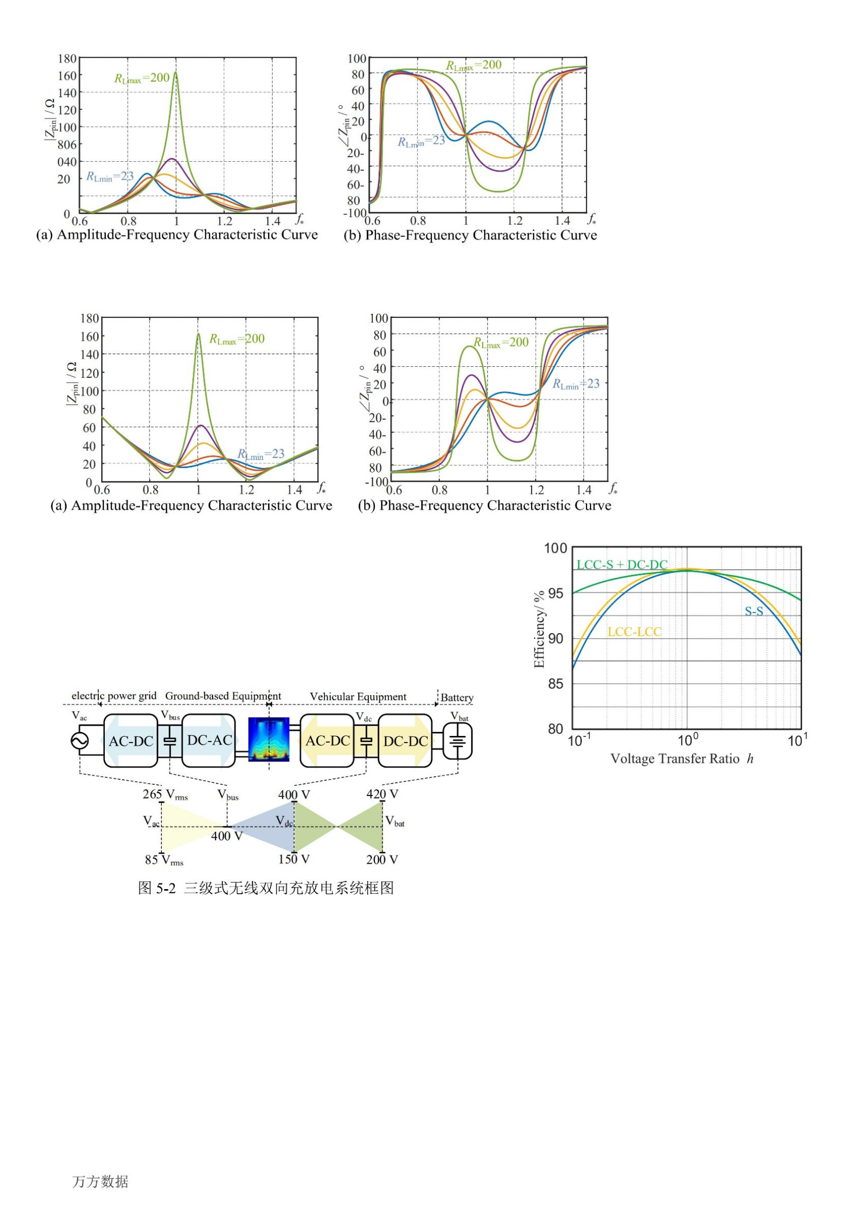
Figure 8: The variation curve of system efficiency with respect to voltage transmission ratio.
3. Optimization of Wireless Charging System
In this paper, with reference to the current GB-T 38775 and SAE J2954 standards, an efficient wireless bidirectional charging and discharging system for electric vehicles of WPT2 level based on the LCC-S compensation network was designed. The complete architecture and control method of the system are presented in Figure 9.
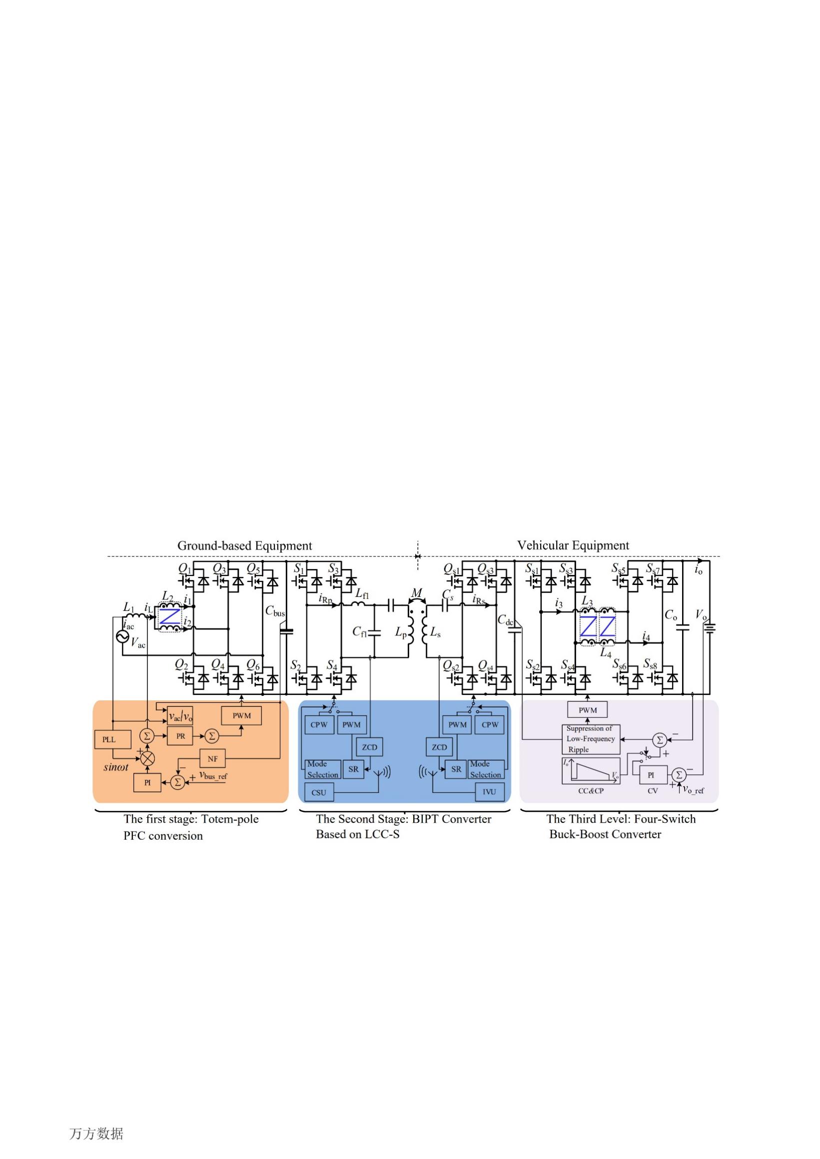
Figure 9: Block Diagram of Wireless Bidirectional Charge-Discharge System.
The first level of the system is a bidirectional AC-DC converter composed of interleaved parallel totem-pole PFC converters. Compared with the traditional totem-pole PFC control method, the main improvement of the control method used in this system lies in that both the current inner-loop command and the current feedback adopt sinusoidal forms. The output modulation wave of the current inner loop carries phase information, which is used as the reference polarity for PWM modulation. This reduces the bandwidth of the current inner-loop controller and avoids the overmodulation phenomenon when there is a deviation in the phase between the modulation wave and the input voltage. When the system is operating, the ground control unit maintains the stability of the ground bus voltage by regulating the bidirectional AC-DC converter and maintains the sinusoidal grid-connected current.
The second level of the system is a BWPT converter based on LCC-S. The LCC-S compensation network adopts a zero-reactive-power control method, that is, the reactive power at the high-frequency network port is detected by the secondary-side controller as the basis for regulating the external phase shift angle, thereby controlling the transmission of electromagnetic energy. When the system is operating, the ground-side BWPT bridge arm switch operates in the open-loop inverter or synchronous rectification mode by selecting the current system operation mode. Similarly, the vehicle-side BWPT bridge arm switch selects the rectification or inverter operation mode by the system operation mode.
The third level of the system is a bidirectional DC-DC converter composed of an interleaved parallel four-switch buck-boost converter (Interleaved Four Switch Buck-Boost, IFSBB) topology based on coupling inductors. In the existing architecture of the wireless bidirectional charging and discharging system, the low-frequency ripple can flow freely in the bilateral DC buses. In the control system of the IFSBB converter of this system, a resonant controller corresponding to the frequency of the low-frequency ripple is added to achieve the purpose of suppressing the output low-frequency pulsation, avoiding the inflow of low-frequency pulsating power into the vehicle-side DC power supply and load. When the system is operating, the vehicle-mounted control unit achieves the matching of the input and output voltages by adjusting the duty cycle of the bidirectional DC-DC converter and realizes the power control of charging and discharging by adjusting the direction and magnitude of the output current \( {I_{o}} \) .
4. Experimental Validation
4.1. Steady-state and dynamic performance tests
During the performance test of the entire machine, the AC input of the ground-end device is connected to the 230 V AC power grid, the output of the vehicle-end device is connected to the resistor load box, and the DC regulated power supply and the power diode are connected in series and then connected to both ends of the DC load. Suppose \( {V_{ac}} \) and \( {I_{ac}} \) are respectively the AC input voltage and current at the grid side of the ground-end power component, \( {I_{{L_{f1}}}} \) is the output current of the bridge arm of the ground-end power component, and \( {I_{o}} \) is the output current of the vehicle-end.
Figure 10 presents the voltage and current waveforms of the system under different working conditions in the charging mode. During the charging mode test, it operates with a resistive load, and the vehicle-end DC-DC converter is set to the constant voltage output mode. To prevent an excessive inrush current during the startup of the resonant cavity, after sending the startup command, the phase shift angle of the primary bridge arm gradually decreases from 180 degrees to 0 degrees. Correspondingly, the vehicle-end conversion device adopts a command soft-start method to establish the output voltage, and the startup process waveform is shown in Figure 10(a). Figure 10(b) depicts the full-load steady-state operation waveform in the charging mode. Since the DC bus voltage of the ground-end module contains a certain component of low-frequency voltage ripple, and the primary bridge arm of the BWPT operates in a fixed frequency and duty cycle mode, the low-frequency ripple directly enters the resonant cavity and is transferred to the secondary DC bus. Figures 10(c) and 10(d) respectively show the experimental waveforms of the sudden increase and sudden decrease of the output current at 5 A. Whether loading is applied or removed, the bidirectional AC-DC can promptly detect the power change of the DC bus, adjust the AC input current in a timely manner, and maintain its excellent waveform quality.
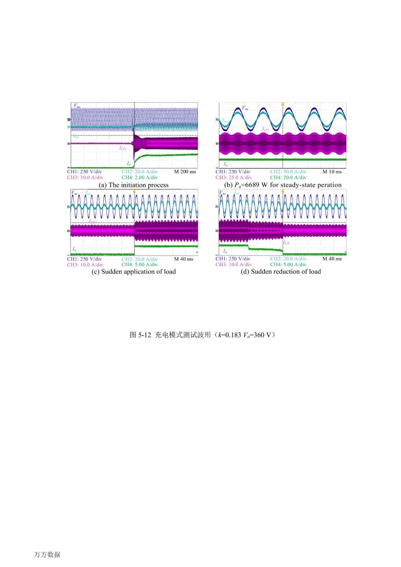
Figure 10: Test Waveform in Charging Mode ( \( k \) = 0.183, \( {V_{o}} \) = 360 V)
Figure 11 presents the voltage and current waveforms of the system under different working conditions in both charging and discharging modes. During the discharging mode test, the DC voltage source is initially loaded onto the DC input port of the vehicle-end converter, and the output capacitor is pre-charged via the NTC resistor. Subsequently, a startup command is sent to enable the ground-end device to operate in grid connection first. The vehicle-end device closes the relay upon receiving the completion signal of the ground-end startup. After the capacitor is charged, the device initiates operation, and the discharge current gradually increases to the commanded set value. The ground-end device receives the energy and feeds it into the power grid. When the system stops, the vehicle-end device stops energy supply first and then the ground-end device is shut down to avoid overvoltage on the DC bus of the ground-end device. The steady-state operation waveforms of the system during half-load and full-load discharging are shown in Figures 11(a) and 11(b), respectively. Through the discharge current \( {I_{o}} \) and the grid-connected current \( {I_{ac}} \) , it can be observed that when the output is at different load powers in the discharging mode, the converter has good control over the DC discharge current on the battery side and the AC current waveform of the grid connection, and possesses favorable port characteristics.
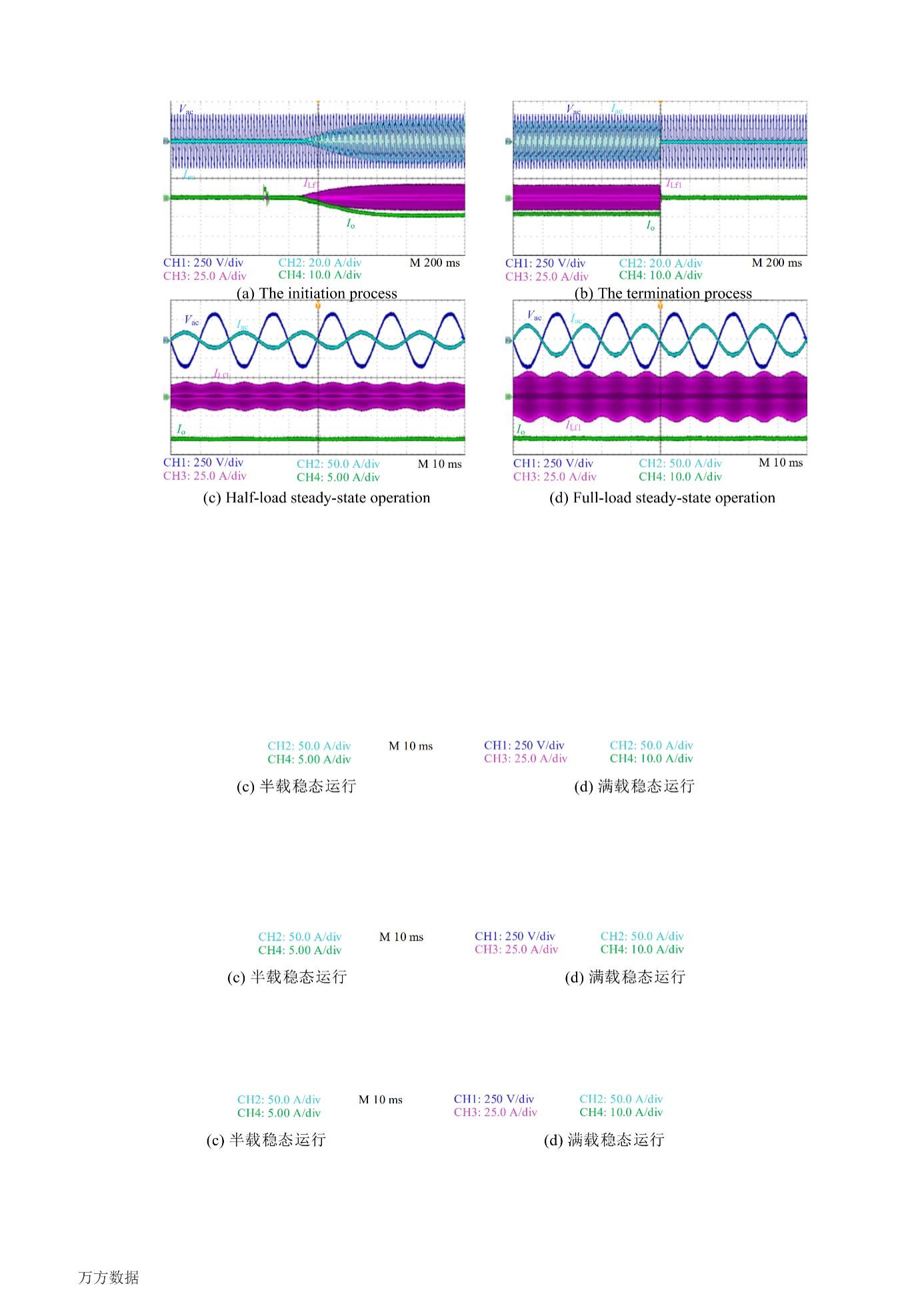
Figure 11: Test Waveform in Discharge Mode ( \( k \) = 0.183, \( {V_{o}} \) = 360 V)
4.2. Test of System Efficiency
This paper employs the power analyzer HIOKI 3390 to test the bidirectional transmission efficiency of the system at different DC voltages under various coupling coefficients respectively. The test method is depicted as shown in Figure 12.
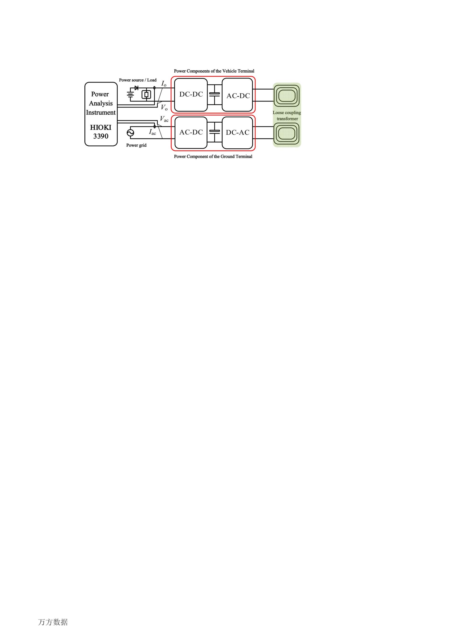
Figure 12: Testing Approaches for Wireless Bidirectional Charge and Discharge Systems.
The efficiency curve results acquired through the test are presented as shown in Figure 13.
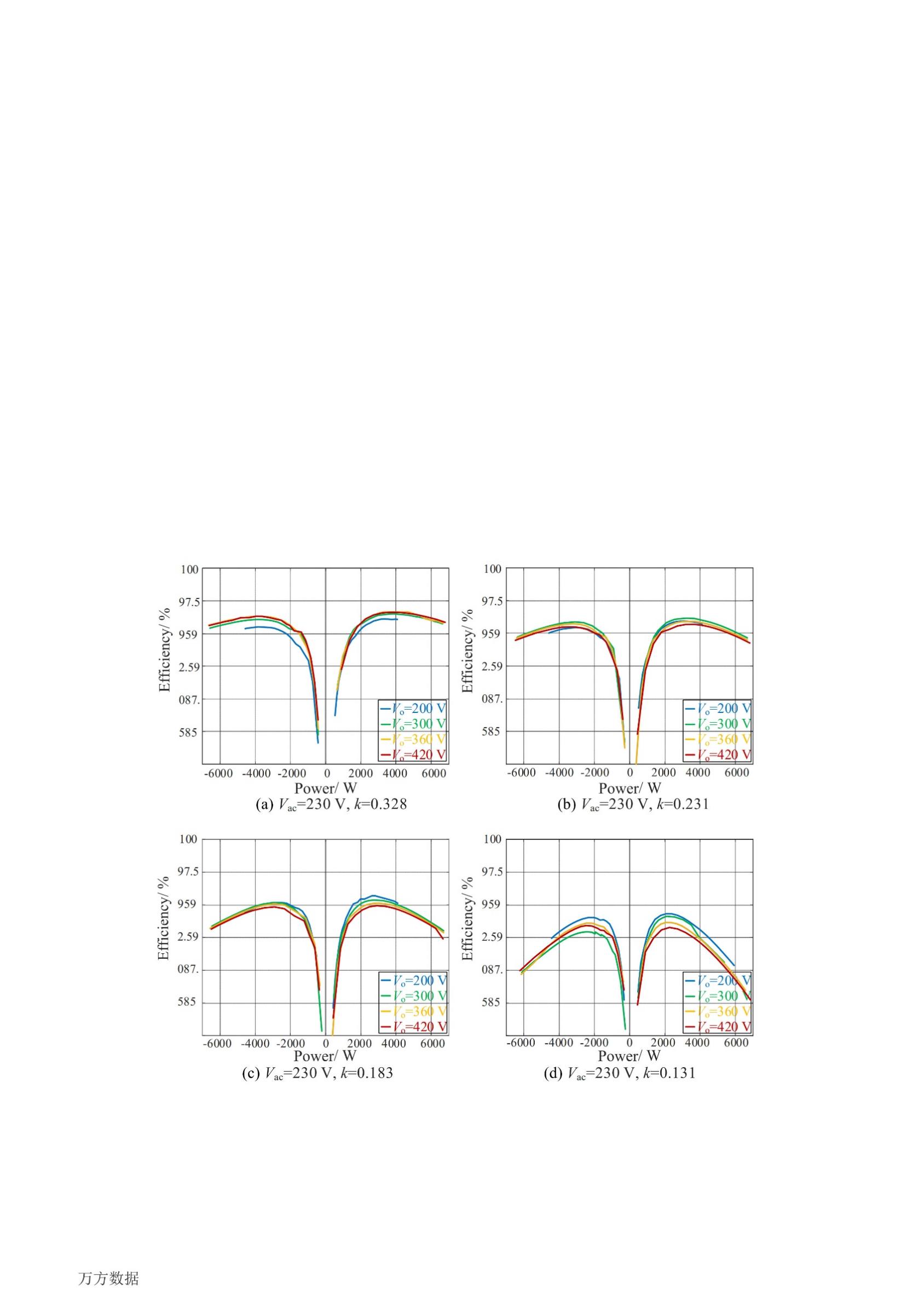
Figure 13: Test Results of Efficiency for Wireless Bidirectional Charge-Discharge System.
The results indicate that when the coupling coefficient is relatively high, the curve of the overall transmission efficiency of the system with respect to the output power is relatively smooth, and the peak transmission efficiency of the main power circuit can reach 96% (the power of the auxiliary power supply is not included, and the total power of the auxiliary power supplies of the vehicle-end and ground-end devices is 40 W). As the coupling coefficient decreases, the peak transmission efficiency of the system also declines, and the smaller the coupling coefficient is, the more obvious the efficiency decrease is with the increase in power. This is because the peak efficiencies of both the AC-DC and BWPT occur around 3500 W. When the transmission power increases, the efficiency of the cascaded system shows a rapid decline trend. Additionally, since the primary side bus of the BWPT link is stabilized at approximately 390 V through the bidirectional AC-DC converter, the secondary side DC bus voltage exhibits the same variation trend when the coupling coefficient decreases, causing the bidirectional DC-DC converter to deviate from the unit voltage transfer ratio. This is also the main reason for the rapid decrease in system efficiency with the increase in output power when the coupling coefficient decreases.
Through exhaustive tests, it can be observed that the system proposed in this paper is capable of conducting full voltage and power range tests within the stipulated offset range. Moreover, the transmission efficiency remains greater than 87.5% at the minimum coupling coefficient, maximum output voltage, and rated transmission power. This is significantly higher than the 80% system transmission efficiency requirement under offset conditions stipulated in the national standard for wireless charging systems of electric vehicles. This validates that it can operate with high efficiency, stability, and reliability under conditions of a larger offset range and a wider DC side voltage range.
5. Conclusion
The main task of this paper is to address the issues of poor anti-offset capability and insufficient width of the voltage range for DC-end matching in the wireless bidirectional charging and discharging system of electric vehicles, with the aim of enhancing the efficiency, stability, and reliability of the system's operation. In light of the abovementioned problems, this paper initially analyses the reactive power compensation capacity and transmission characteristics of the LCC-S resonant network. Based on the loss model of the LCC-S cascaded system, the variation law of the transmission efficiency of the LCC-S and DC-DC cascaded structure with the voltage transmission ratio is deduced. Subsequently, a three-level architecture of an efficient wireless bidirectional charging and discharging system for electric vehicles based on the LCC-S compensation network and a system collaborative control method without control-level data communication are put forward. Finally, the operating characteristics of the proposed system are tested through experiments, validating the feasibility of the system in the field of wireless bidirectional charging and discharging. The relevant research achievements lay a theoretical foundation for the large-scale promotion and application of wireless bidirectional charging and discharging technology in the domain of electric vehicles.
References
[1]. TANG Weiyi, CHENG Zhiyuan.A real-time tracking algorithm for 3D wireless maximum power transfer to a moving device[C]//2020 IEEE PELS Workshop on Emerging Technologies:Wireless Power Transfer (WoW).Seoul:IEEE, 2020:27-34.
[2]. LE-HUU H, BUI G T , SEO C . Efficient compact radiative near-field wireless power transfer to miniature biomedical implants[J].IEEE Antennas and Wireless Propagation Letters, 2023, 22(12):2803-2807.
[3]. YANG Lei, ZHANG Yuanqi, LI Xaojie, et al.Comparison survey of effects of hull on AUVs for underwater capacitive wireless power transfer system and underwater inductive wireless power transfer system[J].IEEE Access, 2022, 10:125401-125410.
[4]. Zhang Shengnan, Wang Haiyun, Wang Ru. Research on Control Strategy for Bidirectional Wireless Power Transmission System in V2G [J]. Journal of Power Supply, 2024, 22(S1): 208-216.
[5]. LEE C H, JUNG G H, AL HOSANI K, et al.Wireless power transfer system for an autonomous electric vehicle[C]//Proceedings of 2020 IEEE Wireless Power Transfer Conference (WPTC).Seoul:IEEE, 2020:467-470.
[6]. Zhang Shengnan, Wang Haiyun, Wang Ru. Research on the Bidirectional Radio Power Transmission System Based on V2G [J]. Modern Electronics Technique, 2022, 45(18): 127 - 132.
[7]. Zhang Zhenli. Research on the Optimization of Two-way Wireless Power Transmission System for V2G Electric Vehicles [J]. Electronic Test, 2021(21): 26 - 28.
[8]. Xiao Li, Xie Yaoping, Hu Huafeng, et al. A Two-Layer Optimization Scheduling Strategy for Electric Vehicle Charging and Discharging Based on V2G [J]. High Voltage Apparatus, 2022, 58(5): 164 - 171.
[9]. Zhou Wei, Lan Jiahao, Mai Ruikun, et al. Energy Management Strategy for Wireless Charging Electric Vehicle in V2G Mode of Photovoltaic Energy Storage DC Microgrid [J]. Transactions of China Electrotechnical Society, 2022, 37(1): 82 - 91.
[10]. ONAR O C, SU G, ASA E, et al. 20-kW Bi-directional Wireless Power Transfer System with Energy Storage System Connectivity[C]// 2020 IEEE Applied Power Electronics Conference and Exposition (APEC). New Orleans, LA, USA: 2020. 3208-3214.
[11]. ZHAO L, THRIMAWITHANA D J, MADAWALA U K, et al. A Push–Pull Parallel Resonant Converter-Based Bidirectional IPT System[J]. IEEE Transactions on Power Electronics. 2020, 35(3): 2659-2667.
[12]. Chen Haowen. Research on Power Regulation and Efficiency Optimization of Bi-directional Inductive Wireless Power Transmission System [D]. Wuhan: Huazhong University of Science and Technology, 2022.
[13]. LI Yong, HU Jiefeng, CHEN Feibin, et al.Dualphase-shiftcontrol scheme with current-stress and efficiency optimization for wireless power transfer systems[J].IEEE Transactions on Circuits and Systems I:Regular Papers, 2018, 65(9):3110-3121.
[14]. JIANG Mengjie, CHEN Changsong, JIA Shuran, et al.An asymmetrical pulsewidth modulation with even harmonics for bidirectional inductive power transfer under light load conditions[J].IEEE Transactions on Industrial Electronics, 2022, 69(9):8939-8948.
Cite this article
Gu,T. (2025). Research on the High-Efficiency Wireless Bidirectional Charging and Discharging System for Electric Vehicles Based on the LCC-S Compensation Network. Applied and Computational Engineering,125,69-80.
Data availability
The datasets used and/or analyzed during the current study will be available from the authors upon reasonable request.
Disclaimer/Publisher's Note
The statements, opinions and data contained in all publications are solely those of the individual author(s) and contributor(s) and not of EWA Publishing and/or the editor(s). EWA Publishing and/or the editor(s) disclaim responsibility for any injury to people or property resulting from any ideas, methods, instructions or products referred to in the content.
About volume
Volume title: Proceedings of the 3rd International Conference on Mechatronics and Smart Systems
© 2024 by the author(s). Licensee EWA Publishing, Oxford, UK. This article is an open access article distributed under the terms and
conditions of the Creative Commons Attribution (CC BY) license. Authors who
publish this series agree to the following terms:
1. Authors retain copyright and grant the series right of first publication with the work simultaneously licensed under a Creative Commons
Attribution License that allows others to share the work with an acknowledgment of the work's authorship and initial publication in this
series.
2. Authors are able to enter into separate, additional contractual arrangements for the non-exclusive distribution of the series's published
version of the work (e.g., post it to an institutional repository or publish it in a book), with an acknowledgment of its initial
publication in this series.
3. Authors are permitted and encouraged to post their work online (e.g., in institutional repositories or on their website) prior to and
during the submission process, as it can lead to productive exchanges, as well as earlier and greater citation of published work (See
Open access policy for details).
References
[1]. TANG Weiyi, CHENG Zhiyuan.A real-time tracking algorithm for 3D wireless maximum power transfer to a moving device[C]//2020 IEEE PELS Workshop on Emerging Technologies:Wireless Power Transfer (WoW).Seoul:IEEE, 2020:27-34.
[2]. LE-HUU H, BUI G T , SEO C . Efficient compact radiative near-field wireless power transfer to miniature biomedical implants[J].IEEE Antennas and Wireless Propagation Letters, 2023, 22(12):2803-2807.
[3]. YANG Lei, ZHANG Yuanqi, LI Xaojie, et al.Comparison survey of effects of hull on AUVs for underwater capacitive wireless power transfer system and underwater inductive wireless power transfer system[J].IEEE Access, 2022, 10:125401-125410.
[4]. Zhang Shengnan, Wang Haiyun, Wang Ru. Research on Control Strategy for Bidirectional Wireless Power Transmission System in V2G [J]. Journal of Power Supply, 2024, 22(S1): 208-216.
[5]. LEE C H, JUNG G H, AL HOSANI K, et al.Wireless power transfer system for an autonomous electric vehicle[C]//Proceedings of 2020 IEEE Wireless Power Transfer Conference (WPTC).Seoul:IEEE, 2020:467-470.
[6]. Zhang Shengnan, Wang Haiyun, Wang Ru. Research on the Bidirectional Radio Power Transmission System Based on V2G [J]. Modern Electronics Technique, 2022, 45(18): 127 - 132.
[7]. Zhang Zhenli. Research on the Optimization of Two-way Wireless Power Transmission System for V2G Electric Vehicles [J]. Electronic Test, 2021(21): 26 - 28.
[8]. Xiao Li, Xie Yaoping, Hu Huafeng, et al. A Two-Layer Optimization Scheduling Strategy for Electric Vehicle Charging and Discharging Based on V2G [J]. High Voltage Apparatus, 2022, 58(5): 164 - 171.
[9]. Zhou Wei, Lan Jiahao, Mai Ruikun, et al. Energy Management Strategy for Wireless Charging Electric Vehicle in V2G Mode of Photovoltaic Energy Storage DC Microgrid [J]. Transactions of China Electrotechnical Society, 2022, 37(1): 82 - 91.
[10]. ONAR O C, SU G, ASA E, et al. 20-kW Bi-directional Wireless Power Transfer System with Energy Storage System Connectivity[C]// 2020 IEEE Applied Power Electronics Conference and Exposition (APEC). New Orleans, LA, USA: 2020. 3208-3214.
[11]. ZHAO L, THRIMAWITHANA D J, MADAWALA U K, et al. A Push–Pull Parallel Resonant Converter-Based Bidirectional IPT System[J]. IEEE Transactions on Power Electronics. 2020, 35(3): 2659-2667.
[12]. Chen Haowen. Research on Power Regulation and Efficiency Optimization of Bi-directional Inductive Wireless Power Transmission System [D]. Wuhan: Huazhong University of Science and Technology, 2022.
[13]. LI Yong, HU Jiefeng, CHEN Feibin, et al.Dualphase-shiftcontrol scheme with current-stress and efficiency optimization for wireless power transfer systems[J].IEEE Transactions on Circuits and Systems I:Regular Papers, 2018, 65(9):3110-3121.
[14]. JIANG Mengjie, CHEN Changsong, JIA Shuran, et al.An asymmetrical pulsewidth modulation with even harmonics for bidirectional inductive power transfer under light load conditions[J].IEEE Transactions on Industrial Electronics, 2022, 69(9):8939-8948.