


1. Introduction
As automobiles advance toward greater intelligence and enhanced safety, the in-vehicle information interaction technology has experienced rapid development. The head-up display (HUD) is a smart information interaction technology that utilizes an optical system to project critical information directly into the view field of operator. The essential data, such as speed, fuel level, navigation, and assistance information, will directly display and the operator could easily get the information without diverting their gaze. This effectively shortens blind time and significantly improves safety [1]. HUD technology firstly developed in the 1950s and utilized in fighter jets for targeting and firing systems [2]. Then, HUD optical systems became increasingly applied in civil, General Motors pioneered integrating HUD technology into the automotive research and development sector in 1988 [1]. Although the technology at the time was limited to projecting simple speed information, this transition garnered significant attention within and beyond the automotive industry [3]. In recent years, HUD for automotive use has made great strides and has become a standard feature of smart cockpits.
Over the past three decades, automotive HUD technology has undergone significant advancements. For the time being, the most widely adopted automotive HUD technology on the market is the Windshield HUD (W-HUD), which developed from the Combination HUD (C-HUD). C-HUD, as an early-stage automotive HUD technology, faces challenges due to the intrinsic defect of the automotive front windshield arc surface. When the front windshield serves as the final reflective screen to show the images, the aberrations introduced by the arc windshield are difficult to be corrected [4]. Therefore, the C-HUD system utilizes a clear glass panel behind the windshield as the final reflective screen. The simple design simplified the optical design process and skipped the aberrations, The drawbacks introduced included limited panel area, short projection distance, and potential safety risks in the traffic accidents. As a result, the C-HUD design was eventually replaced by the W-HUD. The W-HUD utilizes the front windshield of the car as the final reflective element in the optical system. The front windshield of the car displays virtual image information in front of the car by reflecting the virtual image light into the operator's eyes. Due to the variety of windshield designs across different car models, W-HUD requires the customized optical path design. Additionally, traditional W-HUD projects a virtual image over a short distance within a limited field of view (FOV), typically used to display basic driving information such as speed and fuel level. However, this limited information no longer met the growing demands of users. In recent years, with the rise of augmented display technology, augmented reality heads-up display (AR-HUD) has gained increasing attention from the public [5-7]. AR-HUD was considered an upgraded version of W-HUD with updates of more comprehensive information interaction, offering not only near-field virtual images to display basic information but also far-field virtual images that enable the fusion of projected images with the real scene. Compared with traditional HUDs, AR-HUDs offered a wider field of view and longer imaging distance due to the design of multiple focal planes, as well as the ability to generate real-time images that align with the actual scene to assist in driving. Therefore, AR-HUD became the main development direction of HUD in the future [8,9].
Most AR-HUDs were designed with a single focal plane [10], which featured a relatively simple structure. However, this design only displayed two-dimensional images and was unable to dynamically adjust the driver's gaze point at different depths, which might cause visual fatigue and rarely provided a true AR experience. Thus, the need for dual-depth HUDs has increased. The most straightforward method to achieve a dual-focal-plane AR-HUD was by using two independent picture generation units (PGUs) and optical systems [11], which allowed for the creation of two focal planes, but results in a larger size and higher cost. The novel proposed design was the zoom AR-HUD system, which was able to adjust the imaging distance by adjusting the focus between the lenses. Though the design was compacted due to the use of a single optical path, frequent switching of the imaging distance was required to display both interactive and basic information, causing the system instability [12]. A recent study proposed a zoom dual-optical-path AR-HUD system, where the far optical path was designed as a zoom path, and the imaging distance was adjusted according to changes in vehicle speed [13]. However, this approach significantly increased the complexity of optical path design and aberration correction.
Due to the variety of HUD technology, it is necessary to overview the current design for automotive HUD. This review summarized recent advancements in research on various types of HUDs for in-vehicle use. Firstly, a brief introduction to the basic components of HUD systems and their development trends would be conducted. Then, detailed analysis of the typical designs according to HUD types was presented, focusing on imaging principles and optical path design, while identifying the advantages and disadvantages of each type. Furthermore, current challenges associated with each type of HUD were summarized and possible solutions were proposed. Finally, the summary and suggestion of the development of HUD technology for vehicles was given.
2. HUD design and fabrication
In this paper, various types of HUDs were analyzed. Generally, the HUD consists of a picture generation unit, components for designing the optical path, and a combiner (such as a windshield or a transparent glass panel) used to reflect virtual images into the operator's field of view.
The HUDs introduced were listed as follows: First is the C-HUD, a system based on a single standalone glass panel. Although this design has lower cost and complexity, the imaging content and distance are limited due to the constraints of the panel area. Secondly, the current mainstream W-HUD significantly improves imaging quality compared with the C-HUD that was introduced. However, the W-HUD still falls short of meeting the growing demand for intelligent vehicles driven by advancements in AR technology. While W-HUDs are limited to providing basic vehicle information, AR-HUDs have emerged as the future trend in HUD development.
The optical path structure of AR-HUDs can be categorized into single-optical-path and dual-optical-path systems, which were analyzed and compared accordingly. A typical design approach for single-optical-path AR-HUDs involves continuous zoom optical system [14], which utilizes a mechanical structure to adjust the distance between optical elements, enabling the system to achieve varying imaging distances. Leveraging the visual persistence of the human eye, the system alternated the projection of images while adjusting the distance between lenses to simultaneously display basic information in the near field and interactive information in the far field. Another type of single-optical-path AR-HUD is based on the principle of polarization [15]. This design alters the polarization direction of incident polarized light by applying or removing voltage to a liquid crystal polarization direction rotator, and then forms different optical paths through the polarization beam splitter. By utilizing the persistence of vision in the human eye, rapid switching between S-polarized light and P-polarized light enables the human eye to perceive two images at different depths simultaneously.
The dual-optical-path system design has recently predominated in the mainstream. The latest dual-optical-path AR-HUD designs can be categorized into two types based on the location where the multifocal images structure is formed: One type of system forms the images within the PGU system itself [6]. By designing a special projection-type PGU, a single PGU creates two image planes at different projection distances. These images are then reflected through a mirror group and the windshield to form virtual images at varying distances. The other type of system forms the images within the reflective mirror system [16], where two independent regions of a single PGU project two images. Through the proper positioning of the mirrors, one image undergoes multiple reflections in reflective mirror system before being reflected onto the windshield by a freeform mirror. The other image is directly reflected onto the windshield by the freeform mirror, ultimately creating two virtual images at different projection distances.
3. HUD design analysis and challenges
3.1. C-HUD and W-HUD
The C-HUD employs a transparent glass panel as a combiner. The entire optical imaging system of the C-HUD is self-contained, with the combiner positioned directly in front of the operator’s eyes, enabling them to view virtual image content through the transparent glass. This design approach simplifies the optical design process and enhances display performance. However, the limited space above the dashboard restricts the size of the transparent glass panel, resulting in a smaller display area and a shorter viewing distance for the C-HUD. With the combiner placed between the windshield and dashboard, it may obstruct the operator's field of vision, negatively impacting the driving experience. Additionally, the glass panel poses a safety risk in an accident, leading to its rapid replacement by the W-HUD.
The W-HUD utilizes the windshield as a combiner to reflect virtual image light into the operator's eyes, allowing them to directly observe virtual information through the windshield. The irregular surface of a car’s windshield typically introduces optical aberrations during reflection. Moreover, the shape of the windshield varies across different vehicle models, requiring the W-HUD to be designed with a customized light path that accommodates the specific curvature of each model’s windshield. The W-HUD needs to be integrated into the limited space within the dashboard to project dashboard information, so its optical path structure must be simplified while still being capable of correcting aberrations. As a result, the design of the optical path for W-HUD is more challenging and can only provide basic vehicle information. Those limitations prompted the emergence of AR-HUD. The actual effect of each type of HUD is shown in Figure 1.
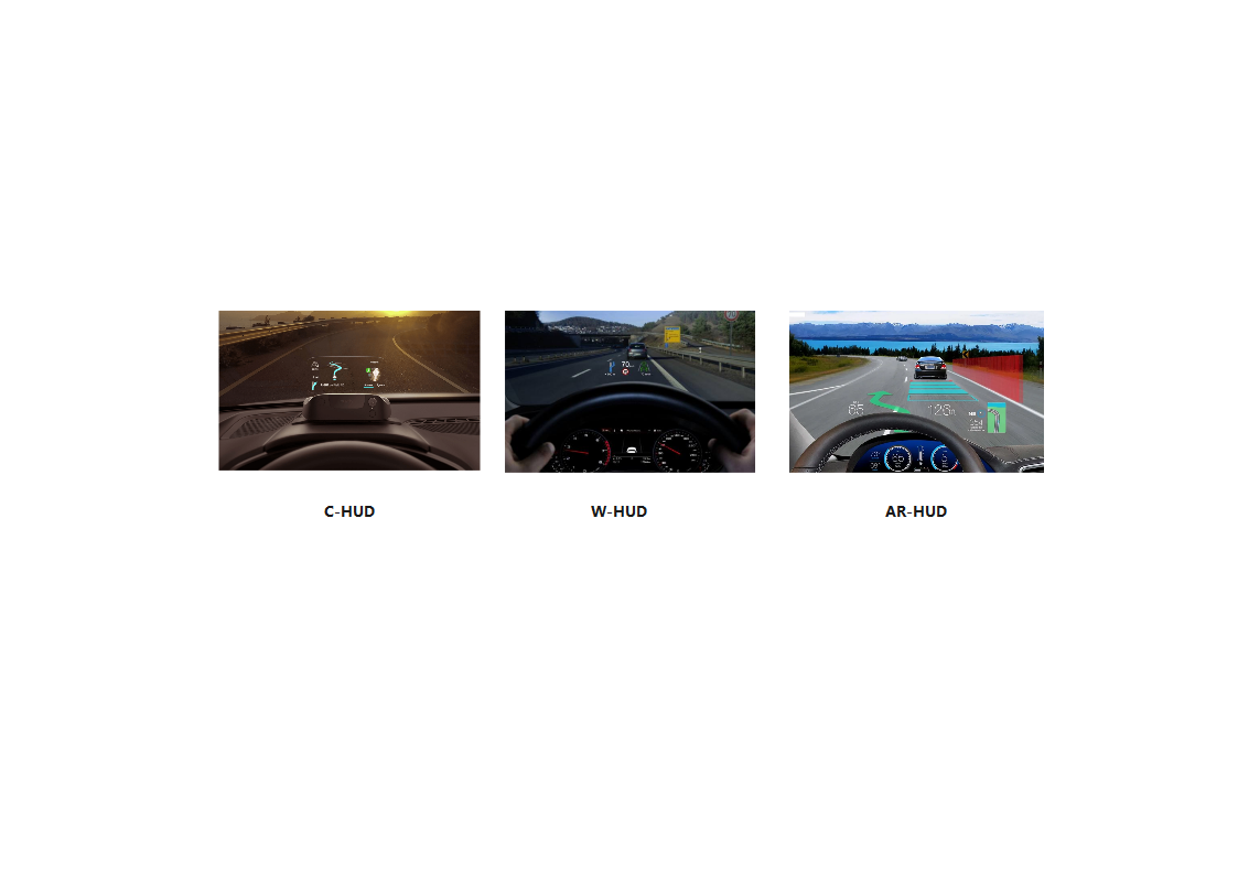
Figure 1: Display effects of three types of HUDs.
3.2. Single optical path AR-HUD
3.2.1. Single-path AR-HUD based on continuous zoom optical system
The design adopted a zoomable optical system [14], which used a single PGU to project images alternately, and a high-speed motor to adjust the distance between the lenses to form two imaging optical paths with different depths of field, which utilized the visual persistence characteristics of the human eye to ultimately realize the effect of simultaneous presentation of the near and far virtual images. As shown in Figure 2, the dashed light path represented the far light path system, the solid light path represented the near light path system, and the components indicated by the dashed lines represented the position after the motor drive.
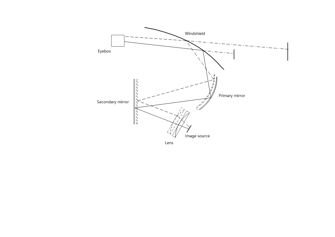
Figure 2: Zoomable single-path AR-HUD optical system.
The zoomable optical system consists of an image source, a lens, a secondary reflector, and a primary reflector. The lens used here is a Fresnel lens with a positive focal length, responsible for correcting the direction of the outgoing light. The secondary reflector is a plane mirror, while the primary reflector is a concave mirror, that focuses the light and reflects it onto the windshield. The Fresnel lens, the secondary mirror, and the primary mirror can be motor-driven, allowing the lenses to move along the optical axis to adjust the system's focal length. Due to the high-speed operation of the motor, multiple images with different depths of field can be projected at high frequency. By utilizing the visual persistence characteristic of the human eye, this enables the simultaneous display of near-field basic information and far-field interactive information.
Although the design was compact and required few complex optical components, thus reducing the size and complexity of the system, the adjustment accuracy of the lenses decreased, aberrations increased as the fatigue accumulation of the motor structure could occur due to the frequency of high-speed motors. The introduced aberrations were difficult to be corrected. As a result, the stability and continuity of imaging were difficult to guarantee.
Overall, the design is highly dependent on the motor, with factors related to motors such as reliability, speed, accuracy, and lifespan are crucial for the system's stability. Furthermore, the power consumption and heat dissipation associated with the high-speed operation of motors cannot be overlooked. Especially in an in-vehicle environment, careful design of power consumption and heat dissipation is necessary to prevent overheating, but the stability and longevity of the entire system could not be easily solved. Finding solutions to these issues remains a challenge.
3.2.2. Single-path AR-HUD based on Liquid Crystal Polarization Direction Rotators
To avoid the defects caused by the motor, another AR-HUD design based on the polarization principle was proposed [15]. The optical system of this design included the lighting system, the PGU system and the imaging system, as shown in Figure 3, where the dashed and solid lines represented the optical paths under different polarization conditions, respectively, for showing near and far virtual images.
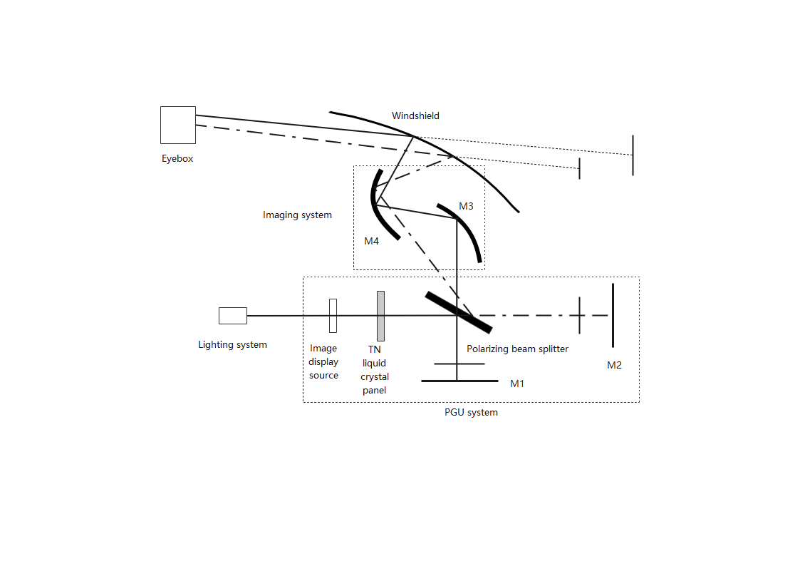
Figure 3: AR-HUD system based on polarization principle.
The PGU system included an image display source, liquid crystal polarization direction rotators, polarization beam splitters, and mirrors M1 and M2. The imaging system utilized two freeform mirrors, M3 and M4. The lighting system evenly illuminated the image display source. A 90° Twisted Nematic (TN) liquid crystal panel was selected as the liquid crystal polarization direction rotator. By applying or removing voltage from the TN liquid crystal panel, the polarization direction of the incident linearly polarized light on the TN liquid crystal panel could be rotated by 90° or remain unchanged, thereby generating S-polarized and P-polarized light. Together with the polarization beam splitter, the S-polarized and P-polarized light formed two separate optical paths. These paths were selectively refracted or reflected onto mirrors M1 or M2 in a timed sequence. By adjusting the positions of mirrors M1 and M2, one optical path passed through freeform mirror M3, then was reflected by freeform mirror M4 onto the windshield, while the other optical path was directly reflected by freeform mirror M4 onto the windshield. This setup ultimately produced images with varying distances and sizes. Due to the fast response characteristics of TN liquid crystals, and by utilizing the visual persistence of the human eye, the S-polarized and P-polarized light could be rapidly switched, allowing the human eye to perceive two images at different distances simultaneously.
Although this design replaced motors with liquid crystal polarization direction rotators and polarization beam splitters to achieve multi-path switching of images, thereby avoiding the drawbacks associated with motors and reducing mechanical complexity. The system was based on polarization principles and the nature of polarized light could lead to some light loss, especially when high brightness and high-resolution display requirements are considered. The control of polarized light could affect both the luminance and quality of the imaging.
Overall, the AR-HUD system based on polarization principles offered a motor-free, high-precision solution through the combination of liquid crystal polarization direction rotators and polarization beam splitters. This design overcomes some of the drawbacks of traditional motor-driven systems, providing a more stable and efficient multi-depth-of-field display. However, it also faces challenges related to optical precision, response speed, and light loss.
3.3. Dual optical path AR-HUD
3.3.1. Dual-path AR-HUD based on the PGU system
The design of this dual optical path system was based on a single PGU and two freeform mirrors [6], where the projective PGU used in this system was designed with a specific projection lens, which used three planar mirrors (M1, M2, M3) to reflect the image surface of the projection system to different locations in order to serve as an image source for the AR-HUD. The structure of the optical path of the entire system and the structure of the PGU is shown in Figure 4, where the near-field optical path is shown in red, and the far-field optical path is shown in blue.
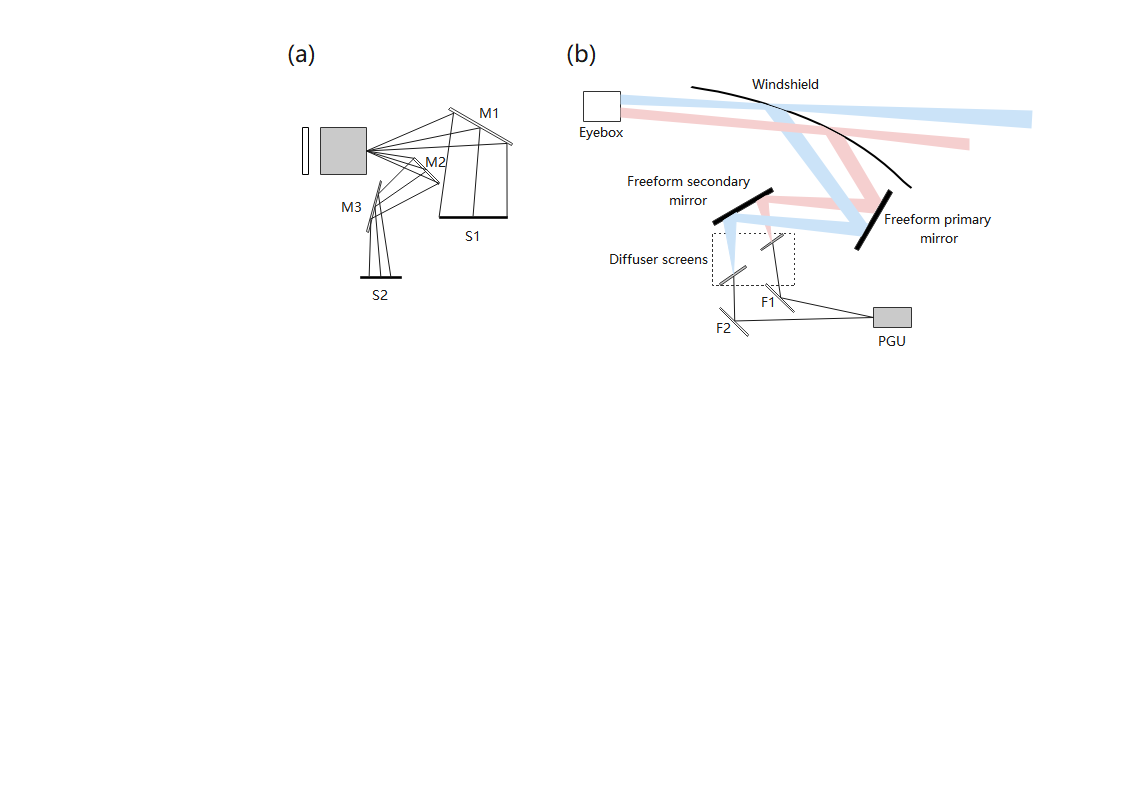
Figure 4: (a) PGU system & (b) Complete optical path system.
In order to provide near-field and far-field image sources for AR-HUD, the projection objective in the PGU system was designed as two sets of optical paths, as shown in Fig. 4(a). The light projected through the projector was divided into two parts, one part of the light was directly reflected by M1 to form the image plane S1, which served as the near-field image source in the AR-HUD system. The other part of the light was reflected by M2, M3 to form the image plane S2, as the far-field image source in the AR-HUD system. Therefore, the PGU system in this design could directly project two images at different distances as image sources. Next, folding mirrors (F1, F2) transferred the image planes of the PGU projection objective to the diffuser screens at different positions as image sources, which were projected onto the windshield after reflection and correction of aberration by two freeform mirrors, finally presenting two virtual images at different distances. The optical path is shown in Fig. 4(b).
This design used a single PGU, which maximized the compression of the optical path and improved space utilization, it also offered high resistance to sunlight backflow, which enhanced the system's reliability. However, the system employed two freeform mirrors, which increased processing complexity and cost, particularly in large-scale production, where high surface accuracy was required. Additionally, in the PGU system, errors in the tilt angles of the flat mirrors (M1, M2, M3) could lead to trapezoidal distortion in the projected image, requiring subsequent correction.
Overall, the design of the system still faces some challenges, such as the heat dissipation issue of the projection-type PGU system under high brightness, and the need for further improvement in its ability to resist sunlight backflow.
3.3.2. Dual-path AR-HUD based on the reflective mirror system
The system was based on a single PGU, a freeform mirror, and three adjustable folding mirrors creating a two-optical-path coupled adjustable AR-HUD optical system [16]. By dividing the PGU projection screen into near-field and far-field regions, the light was split into two optical paths, which were folded through different paths to form virtual images of varying sizes and distances. The far-field optical path was relayed through folding mirrors, and adjusting the distance between these mirrors enabled continuous depth-of-field adjustment within a certain range. The optical path system is shown in Figure 5.
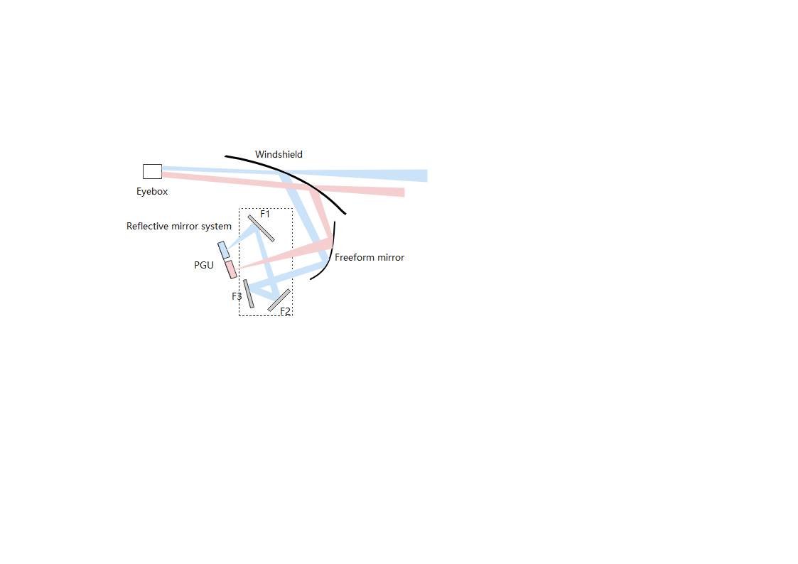
Figure 5: Dual-path AR-HUD based on the reflective mirror system.
Figure 5 presents the results of the dual-path design, where the near-field optical path is represented in red and the far-field optical path in blue. The dashed box indicates the reflective mirror system, which includes three folding mirrors (F1, F2, F3), while both optical paths share a single freeform mirror. The PGU was divided into two parts, with the light representing the near-field being directly reflected by the free-form mirror onto the windshield to form the near-field virtual image. The light representing the far-field was first blocked by F1 and reflected to F2, then reflected from F2 to F3. After multiple folding of the optical path, the light eventually reached the free-form mirror, which reflected it onto the windshield to form the far-field virtual image. This design achieved the presentation of near-field and far-field virtual images simultaneously by folding the light paths through the reflective mirror system. Additionally, to better achieve information interaction, the far-field virtual image of the system needs to blend with real-world objects at varying distances. This requires the far-field virtual imaging system to possess a variable focus capability. This design maintained a fixed center coordinate of the PGU image plane and achieved the capability to display interactive information at any distance within a specific range by adjusting the total distance between the PGU image plane-folding mirror 1 (F1)-folding mirror 2 (F2)-folding mirror 3 (F3)-freeform mirror.
Although the far-field optical path of this design provided a flexible multi-depth virtual image display and improved interaction with real-world information, the resolution and field of view were reduced due to the division of the working area of the PGU projection, leading to smaller display size and lower image resolution. In addition, because the system used multiple folding mirrors, the position and angle errors of their placement could also lead to image distortion.
Overall, the system still faces several challenges. Although the design supports the display of multi-depth virtual images, ensuring smooth and stable transitions between different depths and avoiding image blur caused by depth changes remain critical challenges for the implementation of this technology.
4. Summary
To summarise, HUD mainly includes three components, namely the PGU system, the optical path system, and the combiner. Different types of HUDs have their own advantages and disadvantages as well as their current challenges. C-HUD used a transparent glass plate as the combiner, which reduced the difficulty of aberration correction and simplified the design of the optical system. However, due to spatial constraints on the size and position of the glass plate, its display content was limited, and the viewing distance was relatively short. Additionally, the use of glass panels could affect the operator's field of vision and safety, making this approach largely obsolete in modern electric vehicles. The W-HUD used the windshield as the combiner, offering high integration with the vehicle, good display performance, mature technology, and relatively low cost, making it the mainstream choice for current automobiles. However, it required the specific optical system designed for different windshield surface shapes and only provided basic information about the vehicle. The single-path AR-HUD design based on continuous zoom optical system reduced the size and complexity of the system. However, as the loss of high-speed motors, the precision of mirrors adjustment decreases, making it challenging to ensure the stability and continuity of the imaging. This design was highly dependent on the motor, with its reliability and precision being critical factors for system stability. Additionally, the heat dissipation issue caused by the motor's high-speed operation cannot be overlooked. To address these challenges, non-contact adjustment technologies could be considered, such as electromagnetic or piezoelectric driving technology, to replace traditional mechanical motors and mitigate precision issues caused by mechanical friction and heat accumulation. For heat dissipation, thermal conduction devices can be designed near the motor and lens components to effectively transfer heat away. The single-path AR-HUD based on Liquid Crystal Polarization Direction Rotators leveraged polarization principles, avoiding the drawbacks associated with motors, reducing mechanical complexity, and enabling high-precision optical path switching. However, the nature of polarized light could result in some light loss, which affected the brightness and quality of the imaging. For this design, addressing the issue of light loss was the major challenge. To tackle this, enhancing the backlight system could help mitigate the impact of light loss. For instance, the luminous efficiency of LEDs in the lighting system could be improved. Since LEDs in HUDs often use multi-chip packaging solutions, the number of chips could be adjusted based on illuminance requirements. Additionally, microstructures could be designed on the chips to concentrate light. For example, specific inclined surfaces could be incorporated on the sides of the chips to focus the light beams, thereby increasing the brightness in front of the LED and alleviating the impact of light loss. The dual-path AR-HUD based on the PGU system used a single PGU, which compressed the optical path and improved space utilization and stability. However, this design employed two freeform mirrors, which increased the manufacturing complexity and costs. Additionally, it demanded high precision in the PGU system design, facing challenges related to heat dissipation under high brightness and the need to enhance protection against sunlight backflow. The heat dissipation issue could be addressed by incorporating a thermal conduction system. To tackle the sunlight backflow problem, an additional IR-cut film or polarizer could be applied to the dust cover to block sunlight that did not contribute to imaging. Furthermore, replacing the reflective mirrors with cold mirrors could further enhance the ability of system to prevent sunlight backflow. The dual-path AR-HUD based on the reflective mirror system offered flexible multi-depth virtual image display capabilities and more advanced interaction with real-world scenes. However, by dividing the projection working area of PGU, it reduced the system's resolution and field of view, thereby diminishing the size and clarity of the images. For this design, ensuring smooth and stable transitions between virtual images at different depths and avoiding image blur caused by depth changes are critical challenges. To address these, electronic drive lenses and automatic calibration systems could be integrated to dynamically adjust the optical path length based on real-time environmental conditions. Additionally, introducing enhanced image fusion algorithms to smooth transitions by adjusting the brightness and color of images at different depths through image processing, so as to maintain image clarity and transition stability. For the resolution and field-of-view issues, increasing the pixel density of the projection module could also be considered. The analysis and comparison of various types of HUDs were summarized in Table 1 below.
Table 1: Comparison & Analysis of various HUDs.
HUD types | Advantages | Disadvantages | Challenges | Measures | ||
C-HUD (largely obsolete) | Reduced aberration correction complexity; simplified optical system design | Limited content; short viewing distance; obstructed view and potential safety risks | - | - | ||
W-HUD (Current mainstream choice) | High integration; good performance; low cost and mature technology | Customization requirements and basic info display only | Insufficient info to meet user needs | Developing AR-HUDs as the future trend | ||
AR- HUD | Single-path AR-HUD | Based on continuous zoom optical system | Reduced size and complexity; basic info and real-world interaction | Motor dependence; low precision and the stability issues | Motor losses affect system stability; heat dissipation problems | Use electromagnetic or piezoelectric drives; design heat conduction devices |
Based on Liquid Crystal Polarization Direction Rotators | Reduced mechanical complexity and high-precision optical path switching | Significant light loss; affecting image brightness and quality | Address the impact of optical loss | Enhance backlight; improve the LED efficiency; focus light with microstructures | ||
Dual-path AR-HUD | Based on the PGU system | Compressed optical path; improved space utilization and stability | High manufacturing complexity and costs; stringent PGU design precision | PGU heat dissipation and sunlight backflow prevention challenges | Design heat conduction system; add IR-cut film/polarizer; use cold mirrors | |
Based on the reflective mirror system | Flexible multi-depth virtual image display and enhanced real-world interaction system | Reduced system resolution and field of view; compromised image size and clarity | Ensure smooth depth transitions and avoid image blurring caused by depth changes | Combine electronic lenses with auto-calibration system; enhance image fusion algorithms; Increase pixel density | ||
5. Conclusion
This paper reviewed and analyzed the development history and the latest technologies of automotive HUD systems. It provided an analysis and comparison of typical designs of different types of HUDs from the perspectives of optical path design and imaging principles, and introduced the advantages, limitations, and current challenges of each type of HUD, as well as potential solutions to these challenges. Among these, the C-HUD has been largely phased out due to its limited display content and significant safety concerns. In contrast, the W-HUD, with its high integration, good performance, and mature technology, is currently the mainstream configuration for mid-to-high-end automotive brands. AR-HUDs can be categorized into two types based on their optical path structure. The Single Optical Path AR-HUD reduces the size and complexity of the system but struggles to ensure image stability and quality. On the other hand, the Dual Optical Path AR-HUD offers improved stability and enhanced interaction capabilities with real-world environments but comes with higher manufacturing costs, greater complexity, and a larger size. Overall, compared to C-HUD and W-HUD, AR-HUD provides more comprehensive information. Its near optical path system delivers basic vehicle information, while the far optical path system offers real-world interaction information. Accordingly, its imaging area is larger, the projection distance is farther, and it integrates more seamlessly with the real road environment. In recent years, with continuous technological breakthroughs and cost reductions in AR-HUDs, their application in smart cockpits is becoming increasingly widespread. In the future, there is still room for improvement in areas such as display content, seamless integration of virtual images with the real environment, and overcoming the impact of external sunlight and other environmental factors. These advancements will contribute to enhancing human-machine interaction and the overall cockpit experience in smart electric vehicles.
References
[1]. Smith, S., & Fu, S.-H. (2011). The relationships between automobile head-up display presentation images and drivers’ Kansei. Displays,32(2), 58-68. https://doi.org/10.1016/j.displa.2010.12.001
[2]. Crawford, J., & Neal, A. (2006). A review of the perceptual and cognitive issues associated with the use of head-up displays in commercial aviation. The International Journal of Aviation Psychology, 16(1), 1-19. https://doi.org/10.1207/s15327108ijap1601_1
[3]. Zhou, X., & Yin, G. (2021). Research on symbol color of automotive augmented reality head-updisplay. Journal of Physics: Conference Series, 1875(1), 012013. https://doi.org/10.1088/1742-6596/1875/1/012013
[4]. Li, D. (2022). Application research on wearable computer hardware technology. Electronic Testing, 36(10), 18–20.
[5]. Kim, K. H., & Park, S. C. (2019). Design of confocal off-axis two-mirror system for head-up display. Applied Optics, 58(3), 677–683. https://doi.org/10.1364/AO.58.000677
[6]. Fan, C., Kong, L., Yang, B., & Others. (2023). Design of dual-focal-plane AR-HUD optical system based on a single picture generation unit and two freeform mirrors. Photonics, 10(11), 1192. https://doi.org/10.3390/photonics10111192
[7]. Gabbard, J. L., Fitch, G. M., & Kim, H. (2014). Behind the glass: Driver challenges and opportunities for AR automotive applications. Proceedings of the IEEE, 102(2), 124–136. https://doi.org/10.1109/JPROC.2013.2294642
[8]. Lee, J. W., Yoon, C. R., Kang, J., & Others. (2015). Development of lane-level guidance service in vehicle augmented reality system. International Conference on Advanced Communication Technology (ICACT) (pp. 263–266). IEEE. https://doi.org/10.1109/ICACT.2015.7224799
[9]. Betancur, J. A., Villa-Espinal, J., Osorio-Gómez, G., & Others. (2018). Research topics and implementation trends on automotive head-up display systems. International Journal on Interactive Design and Manufacturing (IJIDeM), 12, 199–214. https://doi.org/10.1007/s12008-016-0350-3
[10]. Wei, S. L., Fan, Z. C., Zhu, Z. B., & Others. (2019). Design of a head-up display based on freeform reflective systems for automotive applications. Applied Optics, 58(7), 1675–1681. https://doi.org/10.1364/AO.58.001675
[11]. Kong, X. X., & Xue, C. X. (2022). Optical design of dual-focal-plane head-up display based on dual picture generation units. Acta Optica Sinica, 42(14), 1422003.
[12]. Ling, L., Wu, Y. F., & Li, M. (2014). A head-up display system for vehicles and cars. CN Patent Application.
[13]. Tian, M., & Xue, C. (2024). Design of a zoom head-up display optical system based on a nodal aberration theory. Applied Optics, 63(18), 5006–5017. https://doi.org/10.1364/AO.516685
[14]. Wang, Y. P. (2017). A zoom optical system and head-up display system. CN104932104B Patent.
[15]. Xie, H. S. (2019). An on-board AR-HUD optical system based on liquid crystal polarization direction rotator. CN208921975U Patent.
[16]. Jiang, Q., & Guo, Z. (2023). AR-HUD optical system design and its multiple configurations analysis. Photonics, 10(9), 954. https://doi.org/10.3390/photonics10090954
Cite this article
Wu,H. (2025). Revolutionizing EVs: A Comprehensive Analysis of Automotive HUD Technologies. Applied and Computational Engineering,125,139-149.
Data availability
The datasets used and/or analyzed during the current study will be available from the authors upon reasonable request.
Disclaimer/Publisher's Note
The statements, opinions and data contained in all publications are solely those of the individual author(s) and contributor(s) and not of EWA Publishing and/or the editor(s). EWA Publishing and/or the editor(s) disclaim responsibility for any injury to people or property resulting from any ideas, methods, instructions or products referred to in the content.
About volume
Volume title: Proceedings of the 3rd International Conference on Mechatronics and Smart Systems
© 2024 by the author(s). Licensee EWA Publishing, Oxford, UK. This article is an open access article distributed under the terms and
conditions of the Creative Commons Attribution (CC BY) license. Authors who
publish this series agree to the following terms:
1. Authors retain copyright and grant the series right of first publication with the work simultaneously licensed under a Creative Commons
Attribution License that allows others to share the work with an acknowledgment of the work's authorship and initial publication in this
series.
2. Authors are able to enter into separate, additional contractual arrangements for the non-exclusive distribution of the series's published
version of the work (e.g., post it to an institutional repository or publish it in a book), with an acknowledgment of its initial
publication in this series.
3. Authors are permitted and encouraged to post their work online (e.g., in institutional repositories or on their website) prior to and
during the submission process, as it can lead to productive exchanges, as well as earlier and greater citation of published work (See
Open access policy for details).
References
[1]. Smith, S., & Fu, S.-H. (2011). The relationships between automobile head-up display presentation images and drivers’ Kansei. Displays,32(2), 58-68. https://doi.org/10.1016/j.displa.2010.12.001
[2]. Crawford, J., & Neal, A. (2006). A review of the perceptual and cognitive issues associated with the use of head-up displays in commercial aviation. The International Journal of Aviation Psychology, 16(1), 1-19. https://doi.org/10.1207/s15327108ijap1601_1
[3]. Zhou, X., & Yin, G. (2021). Research on symbol color of automotive augmented reality head-updisplay. Journal of Physics: Conference Series, 1875(1), 012013. https://doi.org/10.1088/1742-6596/1875/1/012013
[4]. Li, D. (2022). Application research on wearable computer hardware technology. Electronic Testing, 36(10), 18–20.
[5]. Kim, K. H., & Park, S. C. (2019). Design of confocal off-axis two-mirror system for head-up display. Applied Optics, 58(3), 677–683. https://doi.org/10.1364/AO.58.000677
[6]. Fan, C., Kong, L., Yang, B., & Others. (2023). Design of dual-focal-plane AR-HUD optical system based on a single picture generation unit and two freeform mirrors. Photonics, 10(11), 1192. https://doi.org/10.3390/photonics10111192
[7]. Gabbard, J. L., Fitch, G. M., & Kim, H. (2014). Behind the glass: Driver challenges and opportunities for AR automotive applications. Proceedings of the IEEE, 102(2), 124–136. https://doi.org/10.1109/JPROC.2013.2294642
[8]. Lee, J. W., Yoon, C. R., Kang, J., & Others. (2015). Development of lane-level guidance service in vehicle augmented reality system. International Conference on Advanced Communication Technology (ICACT) (pp. 263–266). IEEE. https://doi.org/10.1109/ICACT.2015.7224799
[9]. Betancur, J. A., Villa-Espinal, J., Osorio-Gómez, G., & Others. (2018). Research topics and implementation trends on automotive head-up display systems. International Journal on Interactive Design and Manufacturing (IJIDeM), 12, 199–214. https://doi.org/10.1007/s12008-016-0350-3
[10]. Wei, S. L., Fan, Z. C., Zhu, Z. B., & Others. (2019). Design of a head-up display based on freeform reflective systems for automotive applications. Applied Optics, 58(7), 1675–1681. https://doi.org/10.1364/AO.58.001675
[11]. Kong, X. X., & Xue, C. X. (2022). Optical design of dual-focal-plane head-up display based on dual picture generation units. Acta Optica Sinica, 42(14), 1422003.
[12]. Ling, L., Wu, Y. F., & Li, M. (2014). A head-up display system for vehicles and cars. CN Patent Application.
[13]. Tian, M., & Xue, C. (2024). Design of a zoom head-up display optical system based on a nodal aberration theory. Applied Optics, 63(18), 5006–5017. https://doi.org/10.1364/AO.516685
[14]. Wang, Y. P. (2017). A zoom optical system and head-up display system. CN104932104B Patent.
[15]. Xie, H. S. (2019). An on-board AR-HUD optical system based on liquid crystal polarization direction rotator. CN208921975U Patent.
[16]. Jiang, Q., & Guo, Z. (2023). AR-HUD optical system design and its multiple configurations analysis. Photonics, 10(9), 954. https://doi.org/10.3390/photonics10090954