


1. Introduction
Ships rely on navigation information from various coordinate systems to optimize route planning and ensure navigational safety. By using appropriate coordinate systems, ships can precisely determine their positions in the ocean, thus avoiding collisions, navigating narrow waterways safely, and maintaining the correct course under adverse weather conditions. Furthermore, accurate ship positioning and navigation aid in analyzing the impact of oceanic environmental factors (e.g., currents, wind direction) on navigation, allowing for the planning of energy-efficient and time-saving routes, thereby enhancing operational efficiency. In marine terrain surveying, meteorological observation, ecological investigation, and the exploration of resources such as offshore oil and natural gas, ship positioning and navigation coordinate systems are also indispensable.
Various coordinate systems are employed in the field of navigation. The Earth-Centered, Earth-Fixed (ECEF) coordinate system has its origin at the Earth's center. Its x-axis points toward the intersection of the Greenwich meridian and the equator, its z-axis is aligned with the Earth's rotational axis toward the conventional North Pole, and its y-axis is orthogonal to the X-Z plane, forming a right-handed system. The ECEF system rotates with the Earth and is widely used in geodesy and navigation, with positional parameters represented either as spatial rectangular coordinates (x,y,z) or geodetic coordinates (longitude, latitude, and height).
The inertial coordinate system, with its origin at the Earth's center of mass, has its x-axis pointing toward the vernal equinox, its z-axis aligned with the Earth's rotational axis, and its y-axis forming a right-handed system with the x- and z-axes. This system remains fixed relative to the stars and does not rotate with the Earth, serving as a reference frame for inertial navigation outputs [1]. The geodetic coordinate system relies on the Earth's surface, using latitude and longitude to define positions. It provides an intuitive means of describing geographic locations on Earth and was of significant importance in early maritime navigation. Regarding coordinate transformation relationships, due to the Earth's rotation and revolution, relative motion exists between the ECEF and inertial coordinate systems. Pioneering scientists, such as Euler, developed formulas and methods for converting between these systems, enabling seamless switching and calculations in various navigation scenarios. For local navigation, local planar rectangular coordinate systems are often established to simplify calculations and enhance accuracy. Researchers have worked extensively to define the transformation relationships between local coordinate systems and global coordinate systems, ensuring accurate coordinate conversions in different navigation contexts. Based on these coordinate systems, navigation algorithms and technologies have evolved. Dead reckoning utilizes accelerometers and gyroscopes to measure a vessel's acceleration and angular velocity. Starting from a known initial position, subsequent positions are calculated through integration within a coordinate system. This method does not rely on external signals and can provide partial navigation information even in areas without satellite signal coverage, such as underground tunnels. On the other hand, satellite navigation systems use satellite signals to determine receiver positions in specific coordinate systems. For instance, the GPS system employs the WGS-84 coordinate system, where the receiver's position is calculated by measuring distances to satellites and applying triangulation methods.
This paper systematically analyzes various coordinate systems, [2] including their definitions, algorithms, and practical applications. The discussion encompasses geodetic coordinate systems, body-fixed coordinate systems, and more, providing a comprehensive evaluation of their roles in ship navigation. Finally, this review outlines future research directions for ship positioning and navigation coordinate systems.
2. Definition and Algorithms of Coordinate Systems
2.1. Geodetic Coordinate System
The geodetic coordinate system, typically uses longitude, latitude, and altitude to represent a ship's position on Earth. The system takes the Earth's center as the origin, the X-axis points to the intersection of the Prime Meridian and the Equator, the Y-axis points to the intersection of 90°E longitude and the Equator, and the Z-axis points to the Earth's North Pole, as shown in Figure 1.
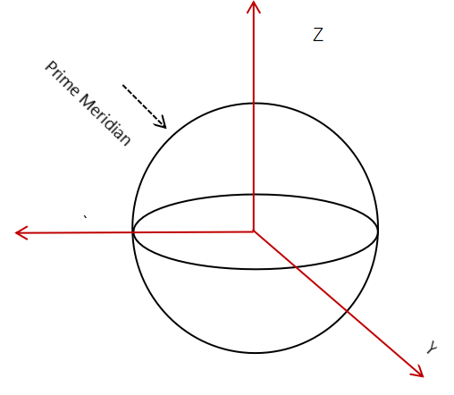
Figure 1: Schematic Diagram of the Geodetic Coordinate System
In the geodetic coordinate system, a ship's longitude and latitude can be directly obtained via global satellite navigation systems such as GPS or BeiDou. Altitude can be measured using devices such as barometric altimeters or radar altimeters.
To calculate the distance between two points A and B with respective longitudes and latitudes (lon1,lat1) and (lon2,lat2), the following steps are applied:
(1) Calculate the differences in latitude (dLat) and longitude (dLon), and convert them to radians:
\( dLat = (lat2 - lat1) × π / 180 \) (1)
\( dLon = (lon2 - lon1) × π / 180 \) (2)
(2) Calculate the value of a:
\( a=sin²(dLat/2)+cos(lat1×π/180)×cos(lat2×π/180)×sin²(dLon/2) \) (3)
(3) Calculate the value of c:
\( c = 2×atan2(√a, √(1 - a)) \) (4)
(4) Calculate the distance d:
\( d = R×c \) (5)
In Equation (5), R represents the Earth's radius, which is typically approximated to an average value of 6,371 kilometers.
To calculate the bearing angle between points A and B, the following steps are used:
(1) Convert longitude and latitude to radians:
\( lat1r = lat1 × π / 180 \) (6)
\( lon1r = lon1 × π / 180 \) (7)
\( t2r = lat2 × π / 180 \) (8)
\( lon2r = lon2 × π / 180 \) (9)
Calculate the bearing angle (θ):
\( θ = atan2(y, x) \) (10)
In Equation (10),
\( y = sin(lon2r - lon1r)×cos(lat2r) \) (11)
\( x=cos(lat1r)×sin(lat2r)-sin(lat1r)×cos(lat2r)×cos(lon2r-lon1r) \) (12)
In the absence of external information such as GPS or BeiDou signals, navigation algorithms commonly employed in the geodetic coordinate system include dead reckoning. The core of dead reckoning is to estimate the current position based on known initial positions, heading, and travel distance.
2.2. Body-Fixed Coordinate System
The body-fixed coordinate system is a coordinate system established with the ship itself as the reference frame. It typically takes the ship’s center of gravity as the origin. The X-axis points in the direction of the ship's longitudinal axis, the Y-axis points in the direction of the ship’s transverse axis, and the Z-axis is perpendicular to the ship’s deck and points upward, as shown in Figure 2.
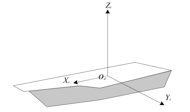
Figure 2: Schematic Diagram of the Ship Body-Fixed Coordinate System
Various sensors installed on the ship (e.g., gyroscopes, accelerometers) are used to measure the ship's attitude angles, including roll, pitch, and yaw.
(1) Roll Angle Calculation:
The roll angle is the rotation of the ship around its longitudinal axis (X-axis). It can be measured by integrating the angular velocity obtained from a gyroscope or by calculating from the accelerometer’s measurements along different axes.
Let the measurements of the accelerometer along the three axes of the body-fixed coordinate system be ax, ay, and az, then the roll angle Ø can be calculated as:
\( Ø=atan2({a_{y}}, {a_{z}}) \) (13)
(2) Pitch Angle Calculation:
The pitch angle represents the rotation of the ship around its transverse axis (Y-axis). Similarly, it can be calculated using a gyroscope or accelerometer.
Using the accelerometer’s measurements along the three axes, the pitch angle θ can be calculated as:
\( θ=atan2(-{a_{x}}, \sqrt[]{a_{y}^{2}+a_{z}^{2}}) \) (14)
(3) Yaw Angle Calculation:
The yaw angle is the rotation of the ship around its vertical axis (Z-axis). It can be determined by integrating the angular velocity from a gyroscope or using other navigation devices, such as a magnetic compass. When using gyroscope integration, the accumulation of integration errors must be considered.
Using the attitude angles, the positional information in the geodetic coordinate system can be converted into the body-fixed coordinate system:
\( [x,y,z]T=R×[X,Y,Z]T \) (15)
Here, (X, Y, Z) represents the position vector in the geodetic coordinate system, and (x,y,z) represents the position vector in the body-fixed coordinate system. The transformation matrix R can be constructed using the attitude angles (roll angle \( α \) , pitch angle θ, and yaw angle \( δ \) ):
\( R=[\begin{matrix}cosψcosθ & cosψsinθsinϕ-sinψcosϕ & cosψsinθcosϕ+sinψsinϕ \\ sinψcosθ & sinψsinθsinϕ+cosψcosϕ & sinψsinθcosϕ-cosψsinϕ \\ -sinθ & cosθsinϕ & cosθcosϕ \\ \end{matrix}] \) (16)
2.3. Transverse Geodetic Coordinate System
The transverse geodetic coordinate system [3] is a coordinate system used to represent positions on the Earth’s surface, primarily focusing on horizontal positioning in contrast to vertical positioning (e.g., altitude), as shown in Figure 3.
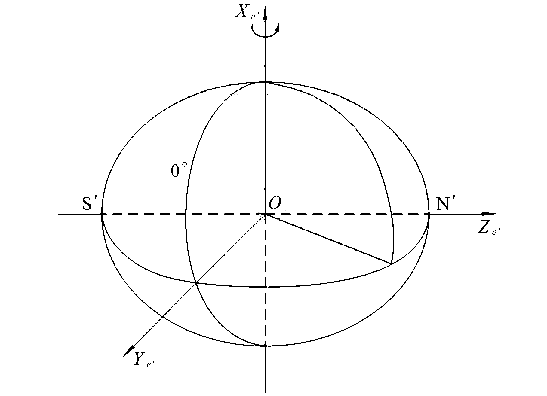
Figure 3: Schematic Diagram of the Transverse Geodetic Coordinate System
In the transverse geodetic coordinate system, latitude is a critical parameter. It is the angle between the line connecting a point on the Earth’s surface to the Earth’s center and the equatorial plane. Latitude ranges from 0° (Equator) to 90° (North Pole or South Pole). Locations north of the Equator are in the northern hemisphere, while those south are in the southern hemisphere.
Longitude is also an indispensable part of the transverse geodetic coordinate system. It measures the angular distance of a location east or west of the Prime Meridian, which has a longitude of 0°. Longitude values range from 0° to 180°, with locations east of the Prime Meridian referred to as eastern longitude, and those west as western longitude.
To calculate a ship’s position on a map using the transverse geodetic coordinate system, follow these steps:
(1) Determine Projection Parameters:
Based on the map area and requirements, determine the projection parameters such as the central meridian, scale factor, east offset, and north offset.
(2) Convert Longitude and Latitude to Planar Coordinates:
For a given longitude (λ) and latitude (φ), use the following formulas to convert them into planar coordinates (X, Y):
\( X = (λ - λ₀) * M₀ + X₀ \) (17)
\( Y = (φ - φ₀) * M₀ + Y₀ \) (18)
Here, λ₀ is the longitude of the central meridian, φ₀ is the latitude of the Equator, M₀ is the scale factor at the Equator, and X₀ and Y₀ are the east and north offsets, respectively.
(3) Perform Coordinate Transformation and Projection:
Based on the calculated planar coordinates (X, Y), perform coordinate transformation and projection to obtain the final map coordinates. The specific method of transformation and projection depends on factors such as the map scale, projection type, and coordinate system.
2.4. Grid Coordinate System
The grid coordinate system [4] is constructed by drawing a series of parallel and perpendicular lines on the Earth’s surface to form a grid. Typically based on longitudinal and latitudinal directions, the Earth's surface is divided into equally sized cells (approximately equal after projection) [5]. For example, in a simple planar grid, horizontal lines might represent latitude divisions, and vertical lines might represent longitude divisions, as shown in Figure 4.
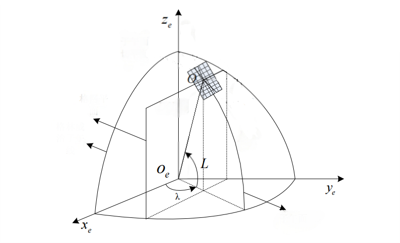
Figure 4: Schematic Diagram of the Grid Coordinate System
Each grid point has a unique coordinate value that specifies its location within the grid. These coordinate values are defined based on a specific origin and the directions of the coordinate axes. Generally, these coordinate values might be integers or numbers represented with a specific precision. For instance, in a grid with a given longitude and latitude as the origin, a point’s coordinate might be expressed as (x, y), where x and y represent the relative horizontal and vertical positions of the point in the grid.
To calculate the row number r and column number c of a given longitude (lon) and latitude (lat) in the grid, the formulas are as follows:
\( r=floor((lat-la{t_{min}})/Δlat) \) (19)
\( c=floor((lon-lo{n_{min}})/Δlon) \) (20)
Given the row number r and column number c of the grid, the corresponding longitude (lon) and latitude (lat) can be calculated as follows:
\( lat=la{t_{min}}+r*Δlat \) (21)
\( lon=lo{n_{min}}+c*Δlon \) (22)
Here, Δlon and Δlat represent the grid intervals in the longitudinal and latitudinal directions, respectively. The geographical area covered by the grid spans a longitude range of \( [lo{n_{min}},lo{n_{max}}], \) and a latitude range of \( [la{t_{min}},la{t_{max}}] \) .
2.5. Pseudo-Earth Coordinate System
The pseudo-Earth coordinate system is a specially processed or transformed coordinate system that is related to the Earth’s coordinate system but exhibits unique properties tailored to specific application needs [6]. As shown in Figure 5:
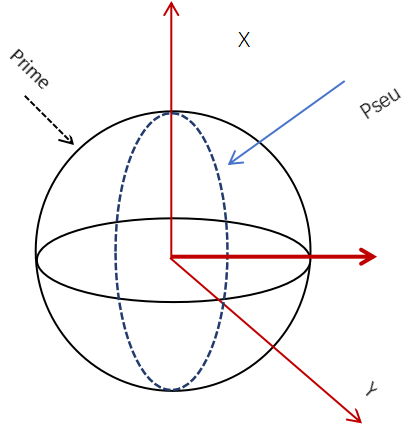
Figure 5: Schematic Diagram of the Pseudo-Earth Coordinate System
The pseudo-Earth coordinate system is constructed to meet specific application requirements and differs from traditional Earth coordinate systems in aspects such as the origin, coordinate axis directions, or coordinate scale [7]. For example, in certain engineering applications or specialized measurements in localized regions, coordinate systems are defined to simplify calculations or meet unique positioning requirements.
The transformation from pseudo-Earth coordinates X_e,Y_e,Z_e) to geographic coordinates (longitude, latitude, and altitude) is given by the following relationships:
\( longitude = f1(X\_e, Y\_e, Z\_e) \) (23)
\( latitude = f2(X\_e, Y\_e, Z\_e) \) (24)
\( altitude = f3(X\_e, Y\_e, Z\_e) \) (25)
The specific forms of the functions f1, f2 and f3 depend on the definition and transformation rules of the pseudo-Earth coordinate system.
Conversely, the transformation from geographic coordinates (longitude, latitude, and altitude) to pseudo-Earth coordinates (X_e,Y_e,Z_e) is as follows [7]:
\( X\_e = g1(longitude, latitude, altitude) \) (26)
\( Y\_e = g2(longitude, latitude, altitude) \) (27)
\( Z\_e = g3(longitude, latitude, altitude) \) (28)
The specific forms of the functions g1, g2 and g3 are determined by the definition and transformation rules of the pseudo-Earth coordinate system.
3. Analysis of Applications in Ship Navigation
The geodetic coordinate system is highly intuitive, as it uses longitude and latitude to represent positions, aligning with the traditional understanding of geographic locations. This makes it easy to comprehend and communicate. It is globally standardized, meaning ships can use it for positioning anywhere without requiring coordinate transformation. Additionally, it has excellent compatibility with navigation devices. Many maritime navigation systems, such as GPS and BeiDou [8], rely on the geodetic coordinate system, directly providing ship positions within this framework.
However, the geodetic coordinate system involves complex calculations. For certain navigation computations, such as distance and bearing calculations, spherical trigonometry is required, which demands significant computational power and advanced devices. Furthermore, it is less suitable for high-precision navigation in small areas. The system’s relative lack of precision in localized regions makes it unsuitable for precise navigational operations [9].
The body-fixed coordinate system directly reflects the motion state of the vessel. Within this system, the ship’s attitude, velocity, and acceleration can be intuitively described. It is highly convenient for analyzing local motion. For example, in specific scenarios such as navigating narrow waterways or handling complex sea conditions, the body-fixed coordinate system facilitates the analysis of the ship’s relative motion with its surroundings, providing more accurate information for safe navigation. Additionally, it has excellent compatibility with the ship’s onboard sensors and control systems.
However, the body-fixed coordinate system is established relative to the ship itself, meaning each vessel has its own unique coordinate system, which limits its global applicability. It is also heavily influenced by the ship’s motion state, which directly affects the definition and orientation of the coordinate system. Moreover, it cannot directly represent the geographic location of the vessel on the Earth’s surface.
The transversel geodetic coordinate system, such as the planar rectangular coordinate system, is highly intuitive when representing small geographic areas. It simplifies distance and area calculations and is well-suited for integration with other planar datasets.
However, this coordinate system introduces distortions when representing larger areas of the Earth's surface. Since the Earth is approximately spherical, projecting its surface information onto a plane inevitably results in distortions in shape, area, and distance. For instance, the commonly used Mercator projection (a transverse cylindrical projection) stretches landmasses in high-latitude regions, which can mislead tasks such as precise route planning in high-latitude navigation [10]. Different transverse geodetic coordinate systems are suited to different areas, making it difficult to find one system that applies perfectly worldwide. As it is a planar coordinate system, significant errors arise in long-distance navigation or geodetic applications if the Earth’s curvature is not considered.
The grid coordinate system divides geographic space into regular grid cells, which facilitates spatial positioning and indexing. This structured grid is highly advantageous for organizing and storing geographic data. Its clear boundaries and defined extents make it convenient for regional statistical analysis. Grid-based spatial data also offers significant advantages in visualization.
Like other planar coordinate systems, the grid coordinate system introduces distortions when projecting the curved surface of the Earth onto a plane. For large geographic areas, these distortions can impact data accuracy. Additionally, the boundaries of the grid may disrupt the continuity of geographic phenomena. The effectiveness of the grid coordinate system heavily depends on its resolution; higher resolution grids are more accurate but require more storage and computational resources.
The pseudo-Earth coordinate system simplifies computational processes. Many local measurement instruments and systems are designed for and more compatible with pseudo-Earth coordinate systems. These systems can be flexibly defined, allowing customization of parameters such as coordinate origins and axis directions to meet specific application requirements.
However, the pseudo-Earth coordinate system is constructed based on localized or specific needs and cannot provide globally unified geographic positioning and descriptions like global geodetic systems (e.g., WGS-84). This limits its application in global geographic information exchange and navigation. Furthermore, its simplified design may exclude considerations of Earth’s shape, gravity field, and other factors, resulting in reduced accuracy in large-scale or high-precision applications. As the measurement range expands, discrepancies from the real Earth model accumulate, leading to increased coordinate errors. When integrating or interacting pseudo-Earth coordinate data with data from globally accepted coordinate systems, the conversion process becomes complex. This involves parameter transformations, projection conversions, and other steps, which may introduce transformation errors.
4. Conclusion
Coordinate systems play a crucial role in ship positioning and navigation [10]. This paper provides a comprehensive review of the commonly used coordinate systems in ship navigation, including geodetic coordinate systems, body-fixed coordinate systems, transverse geodetic coordinate systems, grid coordinate systems, and pseudo-Earth coordinate systems. Their definitions and algorithms were discussed, and the advantages and disadvantages of these systems in ship navigation applications were analyzed. The performance of different coordinate systems in practical navigation is influenced by various factors [11], such as geophysical conditions, the accuracy of navigation equipment, and the effectiveness of data processing algorithms. In real-world applications, these factors must be considered comprehensively to select the most suitable coordinate system and navigation scheme.
The study of coordinate systems for ship positioning and navigation is an evolving field. With advancements in technology and increasing demands for navigation accuracy, future research directions are expected to focus on the following aspects:
(1) Development of New High-Precision Coordinate Systems:
Continued research and construction of novel high-precision coordinate systems to meet the growing demand for accurate navigation.
(2) Efficient Transformation Algorithms and Data Fusion Techniques:
Development of more efficient coordinate transformation algorithms and data fusion technologies to enhance the performance and adaptability of navigation systems.
(3) Error Source Analysis and Modeling:
Further strengthening of error source analysis and modeling to improve the accuracy and reliability of navigation systems.
(4) International Standardization and Collaboration:
Promotion of international standardization and cooperation to facilitate the standardization and globalization of ship positioning and navigation technologies.
These research efforts will contribute to advancing the precision, reliability, and standardization of ship navigation, addressing the challenges posed by modern maritime operations.
References
[1]. Yan Fu, Jianhui Wang, and Fei Han. Initial Fine Alignment of Strapdown Inertial Navigation System in Earth-Fixed Coordinate System [J]. Journal of Navigation and Positioning, 2019.
[2]. Tao Wang. Research on Modeling and Filtering Algorithms for Integrated Navigation Systems [D]. Beihang University, 2020.
[3]. Yongkan Sun and Pingping Zhang. Beyond-Visual-Range Target Tracking in Polar Regions Based on Transverse Geodetic Coordinate System [J]. Journal of System Simulation, 2018(8).
[4]. Qiang Wang, et al. Research on Satellite Navigation and Positioning Technology in Grid Coordinate System [J]. Bulletin of Surveying and Mapping, 2021(8):56-60.
[5]. Pengfei Zhang, Wei Zhao, and Zhimin Liu. Research and Simulation of Inertial Navigation Algorithm Based on Grid Coordinate System [J]. Navigation and Control, 2020, 19(5):113-119.
[6]. Meng Liu, Yanbin Gao, Guangchun Li, and Dan Zhao. Initial Alignment Algorithm of Strapdown Inertial Navigation System Based on Reconstructed Pseudo-Earth Coordinate System [J]. Journal of China Inertial Technology, 2016(6):16-21.
[7]. Li Wang and Feng Zhang. Analysis of Navigation Positioning Accuracy Based on Pseudo-Geodetic Coordinate System [J]. Surveying and Spatial Geographic Information, 2022, 45(11):189-192.
[8]. Jiang Liu. Application Analysis of Transverse Geodetic Coordinate System in Navigation and Positioning [J]. Acta Geodaetica et Cartographica Sinica, 2023, 52(5):785-794.
[9]. Jianhua Cheng, et al. Review of Inertial Navigation System Technology Development [J]. Journal of China Inertial Technology, 2021, 29(1):1-11.
[10]. Jianhua Cheng, Jiaxin Liu, and Lin Zhao. Overview of Polar Region Navigation and Positioning Support Development [J]. China Ship Research, 2021, 16(5):16-29.
[11]. Chunbao Liu and Jun Wu. Review of the Development of Foreign Navigation Satellite Systems in 2020 [J]. International Space, 2021(2):55-60.
Cite this article
Yu,S. (2025). Review of Ship Positioning and Navigation Coordinate Systems. Applied and Computational Engineering,144,19-28.
Data availability
The datasets used and/or analyzed during the current study will be available from the authors upon reasonable request.
Disclaimer/Publisher's Note
The statements, opinions and data contained in all publications are solely those of the individual author(s) and contributor(s) and not of EWA Publishing and/or the editor(s). EWA Publishing and/or the editor(s) disclaim responsibility for any injury to people or property resulting from any ideas, methods, instructions or products referred to in the content.
About volume
Volume title: Proceedings of the 3rd International Conference on Functional Materials and Civil Engineering
© 2024 by the author(s). Licensee EWA Publishing, Oxford, UK. This article is an open access article distributed under the terms and
conditions of the Creative Commons Attribution (CC BY) license. Authors who
publish this series agree to the following terms:
1. Authors retain copyright and grant the series right of first publication with the work simultaneously licensed under a Creative Commons
Attribution License that allows others to share the work with an acknowledgment of the work's authorship and initial publication in this
series.
2. Authors are able to enter into separate, additional contractual arrangements for the non-exclusive distribution of the series's published
version of the work (e.g., post it to an institutional repository or publish it in a book), with an acknowledgment of its initial
publication in this series.
3. Authors are permitted and encouraged to post their work online (e.g., in institutional repositories or on their website) prior to and
during the submission process, as it can lead to productive exchanges, as well as earlier and greater citation of published work (See
Open access policy for details).
References
[1]. Yan Fu, Jianhui Wang, and Fei Han. Initial Fine Alignment of Strapdown Inertial Navigation System in Earth-Fixed Coordinate System [J]. Journal of Navigation and Positioning, 2019.
[2]. Tao Wang. Research on Modeling and Filtering Algorithms for Integrated Navigation Systems [D]. Beihang University, 2020.
[3]. Yongkan Sun and Pingping Zhang. Beyond-Visual-Range Target Tracking in Polar Regions Based on Transverse Geodetic Coordinate System [J]. Journal of System Simulation, 2018(8).
[4]. Qiang Wang, et al. Research on Satellite Navigation and Positioning Technology in Grid Coordinate System [J]. Bulletin of Surveying and Mapping, 2021(8):56-60.
[5]. Pengfei Zhang, Wei Zhao, and Zhimin Liu. Research and Simulation of Inertial Navigation Algorithm Based on Grid Coordinate System [J]. Navigation and Control, 2020, 19(5):113-119.
[6]. Meng Liu, Yanbin Gao, Guangchun Li, and Dan Zhao. Initial Alignment Algorithm of Strapdown Inertial Navigation System Based on Reconstructed Pseudo-Earth Coordinate System [J]. Journal of China Inertial Technology, 2016(6):16-21.
[7]. Li Wang and Feng Zhang. Analysis of Navigation Positioning Accuracy Based on Pseudo-Geodetic Coordinate System [J]. Surveying and Spatial Geographic Information, 2022, 45(11):189-192.
[8]. Jiang Liu. Application Analysis of Transverse Geodetic Coordinate System in Navigation and Positioning [J]. Acta Geodaetica et Cartographica Sinica, 2023, 52(5):785-794.
[9]. Jianhua Cheng, et al. Review of Inertial Navigation System Technology Development [J]. Journal of China Inertial Technology, 2021, 29(1):1-11.
[10]. Jianhua Cheng, Jiaxin Liu, and Lin Zhao. Overview of Polar Region Navigation and Positioning Support Development [J]. China Ship Research, 2021, 16(5):16-29.
[11]. Chunbao Liu and Jun Wu. Review of the Development of Foreign Navigation Satellite Systems in 2020 [J]. International Space, 2021(2):55-60.