


1. Introduction
EEG signal is one of the important signals in human physiology, with the rapid development of modern information technology, more and more researchers have begun to study the EEG signal, which has been applied in many fields such as neuroscience, clinical medicine and psychology, etc., and its rich brain information can provide reference and analysis for the clinical diagnosis (e.g., physiological diseases such as Parkinson's, epilepsy, etc.[1]), psychological diseases (depression, insomnia, etc.[2]) detection and analysis. ) detection provides reference and analysis. With the increasing research on the brain, EEG signals will play an increasingly important role in brain-computer interfaces and intelligent control [3]. However, most of the EEG signal acquisition devices on the market today are large in size and high in cost, especially the amplification and filtering parts, which must be accomplished by discrete components such as operational amplifiers, capacitive inductors, etc., and there are limitations in the environment in which they can be applied [4-5].
This study developed a rechargeable, portable EEG signal acquisition system, which can simultaneously collect 16-channel EEG signals, covering most of the collection points of the brain, supporting wireless Bluetooth transmission function, with small size, low power consumption, rich application scenarios, etc., and the use of lithium batteries for power supply, the addition of the charging management chip as well as the function of the battery power prompts, which makes it convenient for the user to determine the battery status directly through the LED lights on the board. The added charging management chip and battery power indication function facilitate users to judge the battery power status directly through the LED lights on the board, and the system also reserves the relevant interface for charging the lithium battery, which further improves the portability.
2. General System Design
Figure 1 illustrates the overall structure of the system, which is segmented into six parts: acquisition electrodes, analog front-end pre-processing circuits, ADS1299 acquisition circuit module, master control PIC32MX250F128B microcontroller circuit, AC6328A Bluetooth wireless communication module and power management circuit. The distribution position of the electrodes on the EEG cap follows the 10-20 international electrode placement system [6], which is used to continuously collect 16-channel EEG signal data, which enters the acquisition circuit after suppression of high-frequency noise by the pre-processing circuit, and amplifies the 16-channel EEG signals by using the cascade connection of the two ADS1299s, and the analog-to-digital converter to form the 24-bit digital EEG signal data, and then sends the data through the SPI communication protocol to the PIC32MX250F128B microcontroller (Micro Control Unit) circuit, the microcontroller packages the EEG data, and then sends the data to the Bluetooth through the UART serial port, and then the AC6328A low-power Bluetooth (BLE) module completes the data transmission to the upper computer, and then displays the waveforms on the computer side. The power management circuit utilizes a lithium battery to supply power to each module, aiming to reduce weight.
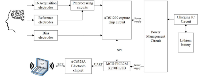
Figure 1: Overall system structure
2.1. Preprocessing Circuit
EEG signals are microvolt signals with amplitude mainly concentrated in 5~100uV and frequency in the range of 0.5Hz~100Hz [7], which are easily interfered by high frequency signals, environment, utility frequency 50Hz and other signals, and the signal-to-noise ratio is very low. To enhance the EEG signal-to-noise ratio and preserve more effective EEG signals, this scheme uses an analog front-end preprocessing circuit composed of an AD8244 unit gain buffer, a low-pass filter, and an electrostatic protection chip in hardware.
Because the system is directly acting on the human body, the safety of the system is a factor that must be considered. Each EEG signal acquired via the EEG cap first passes through a low-pass filter and an ESD protection circuit, the schematic diagram of which is depicted in Figure 2. The system uses a total of four such circuit combinations to protect the EEG signals in all 16 acquisition channels.
Considering that the electrodes at the front end and the hair and scalp friction may generate electrostatic discharge when wearing the EEG acquisition device, it is important to prevent static electricity from causing interference or even damage to the subsequent chip work. Electrostatic discharge protection chip TPD4E1B06 connected to each electrode and ground, with 4-channel bi-directional ESD function, low-pass filter connected to the ESD protection device after the value of 10kΩ resistor and 0.1uF capacitance composed of a first-order RC anti-alias filter, the cut-off frequency of 159Hz, can filter out the majority of high-frequency noise in the EEG signal.
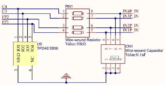
Figure 2: Preprocessing Circuit
Figure 3 illustrates the circuit design of the AD8244 portion of the system.The AD8244 is a four-channel precision unit gain buffer with extremely low current noise, which naturally isolates the high-impedance inputs from the low-impedance nodes and effectively reduces the magnitude of parasitic leakage currents, which can in turn affect performance. The unique pin arrangement simplifies routing, eliminates the need for pin-to-pin alignment, and enhances robustness.
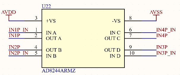
Figure 3: AD8244 circuit design
2.2. EEG signal acquisition circuit
The EEG signal acquisition module is built on the core of ADS1299 chip produced by TI [8], which integrates 8-channel low-noise, 24-bit high-precision synchronous sampling analog-to-digital converters, programmable gain amplifiers (PGAs), and EMI filters. The sampling rate ranges from 250 S/s to 16 kS/s, and the programmable amplifier can be configured with 1, 2, 4, 8, 12, and 24 times gain through embedded software. The chip also has a flexible multiplexer (MUX) [9], through the register configuration can be accomplished by internal signals, temperature and other parameters of the detection, but also set the bias, with the back-end amplifiers to complete the acquisition of external EEG signals. ADS1299 will be filtered, amplified by EEG signals, and ultimately through the A/D converter will be converted from analog signals to digital signals, which are input to the main control chip through the SPI communication protocol. The analog signal is converted to digital signal by the A/D converter and input to the main control chip through SPI communication protocol. The system uses two ADS1299 acquisition chips to acquire 16 channels of EEG signals.
The ADS1299 offers two methods to connect multiple devices with an optimal number of interface pins: cascade mode and daisy-chain mode. This system uses cascade mode, which together create a 16-channel acquisition system. The SPI data interfaces, SCLK, DIN, and DOUT pins, are shared between the two ADS1299s, and each chip has its own independent chip-select signal, CS, to manage the data acquisition and transmission across the multiple ADS1299s. The schematic diagram of the acquisition circuit design is shown in Figures 4 and 5. The front and rear two ADS1299 chips respectively handle the acquisition of the first 8 channels of signals (IN1N~IN8N) and the last 8 channels of signals (IN9N-IN16N). Except for the chip select signal (CS), their pin connections are identical.
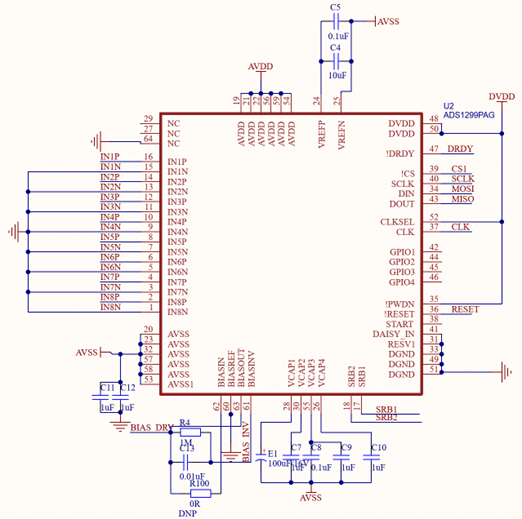
Figure 4: Schematic diagram of the front 8-channel signal acquisition circuit
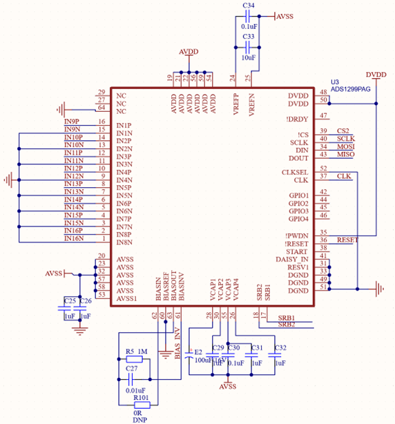
Figure 5: Schematic diagram of the rear 8-channel signal acquisition circuit
2.3. MCU Circuit
The main control chip using the United States Microchip Technology Corporation (Microchip Technology) production of PIC32MX250F128B, the chip is a 32-bit microprocessor, based on the 50 MHz/83 DMIPS MIPS32 M4K core, which helps to reduce the code large, improve the speed of the code operation, with up to 256 KB of flash memory and 64 KB SRAM It supports rich peripheral resources such as two UART serial ports and two 4-wire SPI modules. Most of the pins of the chip can be multiplexed, and the functions of some peripherals can be realized by configuring the values of the relevant internal registers, which increases the flexibility and functions of the chip. The master chip connects with ADS1299 to acquire EEG data through SPI communication protocol, and packages the data and sends it to the Bluetooth module through UART serial port to realize data transmission.
2.4. Power supply part
For the acquisition of microvolt-level signals, the design of the power supply is a significant part of the whole system, which can directly affect the accuracy of the acquired signals. It consists of power supply charging management circuit and all levels of LDO two parts, the role of the power supply charging management circuit is to boost the 3.7V lithium battery to 5V after the input to all levels of the LDO circuit, and the second is to plug in the external 5V power supply to the lithium battery charging.
Figure 6 shows the schematic design of the power charging management circuit, the circuit is based on the core of the IP5305 chip produced by the British set of core technology to build its output current up to 2.4A, high boost conversion efficiency, low quiescent current, integrated lithium battery charging management, the battery power prompts the multifunctional power management chip. The lithium battery is connected to pin 7 of the chip through a 1uH inductor. By the No. 8 pin boost output 5V, battery power tips by four LED lights, they are designed to the chip's 2, 3, 4 pins, the chip began to work after the current lithium battery can be viewed after the power situation. 1 pin for the external 5V input pin, activated when the system is powered off for the lithium battery charging, the entire system switch by the No. 5 pin of a single-pole, single-throw switch control.
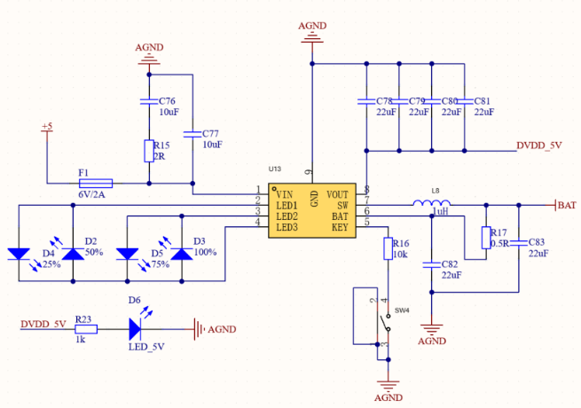
Figure 6: IP5306 Schematic Design
The LDO chips include RT9080, TPS60403, TPS73225 and TPS7A6301. RT9080 can output 3.3V to supply power for the following LDO chips, microcontroller, ADS1299 digital terminal power supply and Bluetooth chip. Use TPS7A6301 to complete the ADS1299 positive 2.5V voltage input, TPS60403 voltage inverter and TPS73225 cascade to complete the 3.3V voltage to -2.5V voltage to meet the ADS1299 negative -2.5 voltage input.
3. Software Design
The embedded software of the acquisition system adopts the Arduino IDE integrated development environment developed by a European development team for program writing. It supports program downloading and debugging through the UART serial port, and realizes continuous 16-channel EEG signal data acquisition by programming the registers of two ADS1299s, and transmits the data according to the SPI communication protocol, and Fig. 7 is the flowchart of the embedded software of the system:
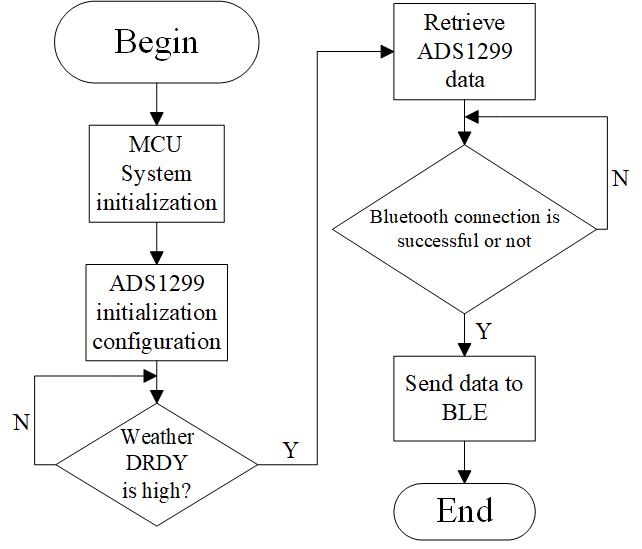
Figure 7: System flow chart
The acquisition system will be initialized after the system is powered on, mainly including ADS1299 initialization, microcontroller system clock initialization, external interrupt initialization, and UART serial port initialization[10]. The ADS1299 initializes by first pulling PWDN high to power up the internal chip, followed by pulling RESET low to reset the chip, pulling the CS pin low, and chip selecting the chip. Configure the values of the internal registers of the two ADS1299 through SPI respectively, when the chip acquisition of data is completed, the data preparation pin DRDY jumps to a low level and connects to the external interrupt pin of the microcontroller, the microcontroller detects whether the external interrupt is generated by the falling edge, and once it is generated, it will enable the SPI communication to read the 24-bit EEG data from the acquisition chip, pack it in a certain format, and utilize serial communication mode to The data packet is sent to the host computer through the Bluetooth module. The upper computer end of the acquisition system establishes a data reception environment using Java software, realizes the data storage and waveform display function of EEG data, and can get more pure EEG signals through the upper computer software setting of trap filtering and band-pass filtering and other processing.
4. Results
The final product of the entire acquisition system is shown in Figure 8, and the overall dimensions of the PCB board are: 7.45cm long and 5.6cm wide. Connects to external EEG cap via 25-pin connector for EEG signal acquisition, including reference electrode, bias electrode and 16 channels of EEG signals. The Li-ion battery charging inlet is designed separately from the connector except for the pins necessary for EEG signals. When the lithium battery needs to be charged, the EEG cap connector can be removed and a new connector can be plugged in to charge the lithium battery. The rightmost side of the system board has a microcontroller UART serial port, which is convenient for program download and debugging. The whole system only needs an external lithium battery can work, small size, easy to use. ADS1299 chip power consumption is less than 40mW, Bluetooth module power consumption is usually between 10 mA and 20 mA, the test, lithium battery in the case of full power can be normal power supply lasts for several hours, the system endurance can meet the test requirements.
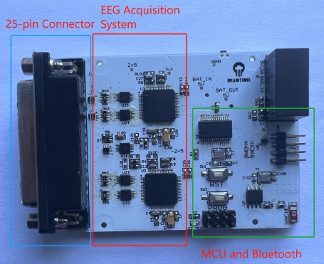
Figure 7: Multi-Channel Acquisition System
The system board is tested according to GB 9706.226 standard, and the input noise of the system is 1.48uV. Various performances of the system satisfy the standard requirements, and it can satisfy the EEG signal acquisition function in most environments.
Figure 9 shows a participant wearing an EEG cap with 10-20 standard electrodes on his head sitting on a stool, acquiring EEG signals through the EEG cap, and displaying the acquired 16-channel real-time EEG signal waveforms through the computer terminal. The acquisition rate of ADS1299 is set to 250 SPS (Sample Per Second) by the embedded software, the trap filter is set to 50 Hz in the upper computer interface, and the type of digital filter is a band-pass filter with a frequency range of 1-50 Hz. It can be seen that the EEG signals acquired by this device are clear and have a high signal-to-noise ratio.
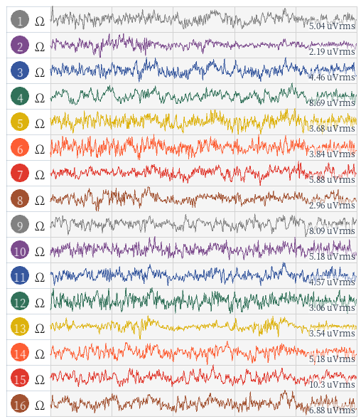
Figure 7: 16-channel EEG signal waveform
The device proposed in this paper is an EEG signal acquisition device realized using Bluetooth wireless transmission and compared with the BT microcontroller based multi-channel EEG signal acquisition system proposed in the literature [10]. Compared to [10], the system proposed in this study has several advantages. Firstly, the overall size of the system is reduced by 25% compared to [10], and secondly, the lithium battery used in this system has a capacity of 1500 mAh, which is three times more than the 500 mAh in [10], which increases the endurance of the system.
5. Conclusions
In this research, a rechargeable, portable wireless EEG signal acquisition system is proposed, which adopts the integrated bioelectricity acquisition special chip ADS1299 as the core for the design of the acquisition circuit and cooperates with a microcontroller and a Bluetooth module to complete the acquisition and transmission of EEG signals. The use of lithium battery power supply and the design of the pre-processing circuit composed of unit gain buffer, RC low-pass filter and electrostatic protection chip, while reducing the cost, it also greatly reduces the noise interference in the acquisition process and increases the safety of the system. After the comprehensive performance test of the overall system, the results show that the system can accurately acquire 16-channel EEG signals, which provides technical guarantee and reference value for other related developments.
References
[1]. Shah S, Zhang L, Bais A. Dynamical system based compact deep hybrid network for classification of Parkinson disease related EEG signals[J]. Neural Networks, 2020, 130.
[2]. Koller-Schlaud K, Strhle A, Baerwolf E, et al. EEG Frontal Asymmetry and Theta Power in Unipolar and Bipolar Depression[J]. Journal of Affective Disorders, 2020, 276(1).
[3]. L. H. Wang et al., "A Low-Power High-Data-Transmission Multi-lead ECG Acquisition Sensor System," in Sensors, vol. 19, no. 22, 4996, Nov.
[4]. S L Wu1, P-T Huang, T C Huang, K N Chen, J C Chiou, K H Chen, C-T Chiu, HM Tong, C T Chuang and W Hwang, Energy-Efficient Low-Noise 16-Channel AnalogFront-End Circuit for Bio-potential Acquisition
[5]. Li, Y., Pan, H., & Song, Q. (2022). ADS1299-Based Array Surface Electromyography Signal Acquisition System. Journal of Physics: Conference Series, 2383(1).
[6]. J. Pascau, M. Desco, P. Rojo, A. Santos, J. Lopez and M. A. Pozo, "Spatial localisation of EEG dipoles in MRI using the 10-20 International System anatomical references," IWISPA 2000. Proceedings of the First International Workshop on Image and Signal Processing and Analysis. in conjunction with 22nd International Conference on Information Technology Interfaces. (IEEE, Pula, Croatia, 2000, pp. 151-156, doi: 10.1109/ISPA.2000.914906
[7]. W. Chen, "Multi-channel EEG signal acquisition system based on nRF52832," 2023 5th International Conference on Communications, Information System and Computer Engineering (CISCE), Guangzhou, China, 2023, pp. 80-83, doi: 10.1109/CISCE58541.2023.10142276.
[8]. Usman Rashid, Imran Khan Niazi, Nada Signal, et al, "An EEG Experimental Study Evaluating the Performance of Texas Instruments ADS1299", Sensors, vol. 18, no. 11, pp. 3720-3737, 2018
[9]. M. Guermandi, R. Cardu, E. F. Scarselli and R. Guerrieri, "Active electrode IC for EEG and
[10]. H.-Y.Hu,L.-H.Wang,I.-C.Kuo,M.-H.Wang,S.-F.WangandP.-C.Huang,"AMulti-ChannelEEGAcquisition Device Based on BT Microcontroller," 2023 International Conference on Consumer Electronics - Taiwan (ICCE-Taiwan), PingTung, Taiwan, 2023, pp. 251-252, doi: 10.1109/ICCE-Taiwan58799.2023.10227057.
Cite this article
Wang,H.;Sai,J.;Ji,C. (2025). RETRACTED ARTICLE:Rechargeable, Portable Wireless EEG Signal Acquisition System Based on ADS1299. Applied and Computational Engineering,119,212-214.
Data availability
The datasets used and/or analyzed during the current study will be available from the authors upon reasonable request.
Disclaimer/Publisher's Note
The statements, opinions and data contained in all publications are solely those of the individual author(s) and contributor(s) and not of EWA Publishing and/or the editor(s). EWA Publishing and/or the editor(s) disclaim responsibility for any injury to people or property resulting from any ideas, methods, instructions or products referred to in the content.
About volume
Volume title: Proceedings of the 3rd International Conference on Software Engineering and Machine Learning
© 2024 by the author(s). Licensee EWA Publishing, Oxford, UK. This article is an open access article distributed under the terms and
conditions of the Creative Commons Attribution (CC BY) license. Authors who
publish this series agree to the following terms:
1. Authors retain copyright and grant the series right of first publication with the work simultaneously licensed under a Creative Commons
Attribution License that allows others to share the work with an acknowledgment of the work's authorship and initial publication in this
series.
2. Authors are able to enter into separate, additional contractual arrangements for the non-exclusive distribution of the series's published
version of the work (e.g., post it to an institutional repository or publish it in a book), with an acknowledgment of its initial
publication in this series.
3. Authors are permitted and encouraged to post their work online (e.g., in institutional repositories or on their website) prior to and
during the submission process, as it can lead to productive exchanges, as well as earlier and greater citation of published work (See
Open access policy for details).
References
[1]. Shah S, Zhang L, Bais A. Dynamical system based compact deep hybrid network for classification of Parkinson disease related EEG signals[J]. Neural Networks, 2020, 130.
[2]. Koller-Schlaud K, Strhle A, Baerwolf E, et al. EEG Frontal Asymmetry and Theta Power in Unipolar and Bipolar Depression[J]. Journal of Affective Disorders, 2020, 276(1).
[3]. L. H. Wang et al., "A Low-Power High-Data-Transmission Multi-lead ECG Acquisition Sensor System," in Sensors, vol. 19, no. 22, 4996, Nov.
[4]. S L Wu1, P-T Huang, T C Huang, K N Chen, J C Chiou, K H Chen, C-T Chiu, HM Tong, C T Chuang and W Hwang, Energy-Efficient Low-Noise 16-Channel AnalogFront-End Circuit for Bio-potential Acquisition
[5]. Li, Y., Pan, H., & Song, Q. (2022). ADS1299-Based Array Surface Electromyography Signal Acquisition System. Journal of Physics: Conference Series, 2383(1).
[6]. J. Pascau, M. Desco, P. Rojo, A. Santos, J. Lopez and M. A. Pozo, "Spatial localisation of EEG dipoles in MRI using the 10-20 International System anatomical references," IWISPA 2000. Proceedings of the First International Workshop on Image and Signal Processing and Analysis. in conjunction with 22nd International Conference on Information Technology Interfaces. (IEEE, Pula, Croatia, 2000, pp. 151-156, doi: 10.1109/ISPA.2000.914906
[7]. W. Chen, "Multi-channel EEG signal acquisition system based on nRF52832," 2023 5th International Conference on Communications, Information System and Computer Engineering (CISCE), Guangzhou, China, 2023, pp. 80-83, doi: 10.1109/CISCE58541.2023.10142276.
[8]. Usman Rashid, Imran Khan Niazi, Nada Signal, et al, "An EEG Experimental Study Evaluating the Performance of Texas Instruments ADS1299", Sensors, vol. 18, no. 11, pp. 3720-3737, 2018
[9]. M. Guermandi, R. Cardu, E. F. Scarselli and R. Guerrieri, "Active electrode IC for EEG and
[10]. H.-Y.Hu,L.-H.Wang,I.-C.Kuo,M.-H.Wang,S.-F.WangandP.-C.Huang,"AMulti-ChannelEEGAcquisition Device Based on BT Microcontroller," 2023 International Conference on Consumer Electronics - Taiwan (ICCE-Taiwan), PingTung, Taiwan, 2023, pp. 251-252, doi: 10.1109/ICCE-Taiwan58799.2023.10227057.