


1. Introduction
Electroporation is typically a procedure involving exposure of a biological cell-membrane to a particular pulsed electric field (PEF) [1]. Depending upon the biological cell’s features, an appropriate PEF can be adopted for electroporation [2]. The electroporation pulse generation is initially controlled by the pulse application duration, shape of pulse-waveform and high-voltage (HV) applied across the cell-membrane. A broad variety of pulse waveforms are available. These waveforms are different for various applications. The voltage magnitude for pulses can be in the 1-100 kV range whereas the pulse time ranges between milliseconds and nanoseconds [3]. Among the broad set of HV pulse signals for electroporation; exponential, rectangular, combined wide and narrow pulses are popularly exploited [3]. These pulses can be bipolar or monopolar. The exponential and rectangular pulses are generally applied in air and water disinfection applications [4]. The combined wide and narrow pulse duration pulses are employed in risk-free food sterilization applications [5-6].
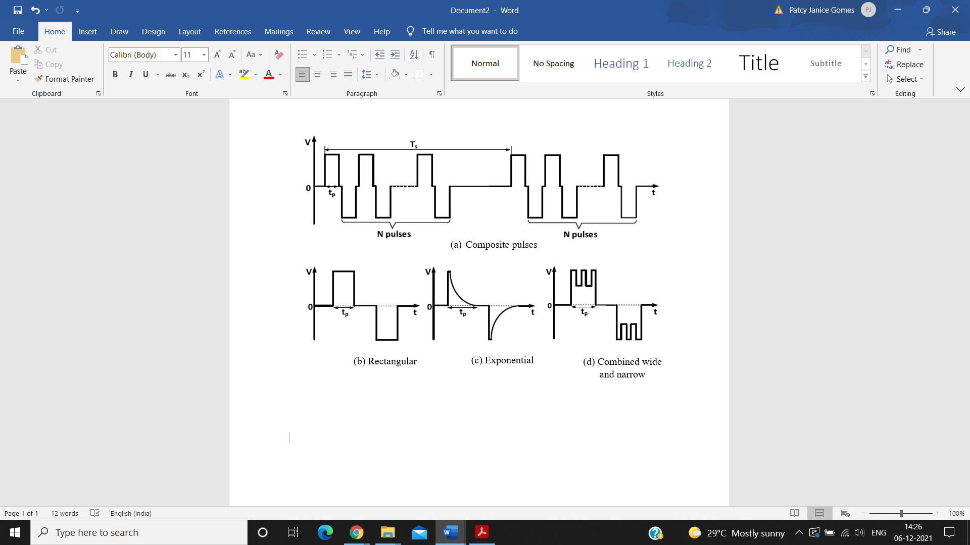
Figure 1. Distinct pulse waveforms employed for electroporation [7].
Initially, classical generators like Marx generators, Blumlein lines and pulse forming generators were commonly employed for generating HV electroporation pulses. But, with progressing HV semiconductor switch technology developments, it is feasible to produce the required HV pulses through power-electronics dependent converters. The methodologies employed in [7-9] utilized HVDC supply for HV pulse generation. These circuits adopted sensorless operation wherein sub-module capacitors’ voltage balancing is assured without the voltage measurements. The methodology employed in [8] incorporated a diode between the adjoining sub-modules. Using an appropriate switching of sub-module insulated bipolar gate transistors, the circuit achieved voltage balance. Another methodology [9] achieved voltage balancing through adopting a particular modulation strategy for bypassing/inserting sub-modules. Though these topologies generated HV pulses their operation significantly deteriorated in case of sub-module failure.
Recently, PWM signals are employed for controlling power electronic components. PWM is a technique of decreasing the mean power delivered through a signal, through effectively chopping it up into discrete parts. PWM is typically exploited for constructing coveted output voltage in power amplifiers. These signals are found to be more effective for regulating power devices. Due to these features, PWM waveforms are largely employed in electroporation applications. Generation of brisk, better quality, high accuracy PWM signals is thus necessary for achieving anticipated performance in electroporation operations. Therefore, this survey article attempts to investigate the diverse generator circuit topologies employed for generating HV pulses and PWM signals for electroporation operations.
1.1. Contributions of the review work
The vital contributions of this review include:
• Investigation of existing circuit designs for PWM signal generation.
• Comparison of distinct circuit topology employed for PWM signal generation.
• Identification of research issues existing in these topologies.
Figure 2. Structure of this survey.
2. Theoretical background
Developments in power electronic equipment or devices, specifically, their high frequency and high power ratings, have allowed utilization of semiconductor-dependent HV pulse generators for PEF applications. Generally, the emerged topologies mimic the traditionally dominating pulse generator converters like the Marx generator [10-12]. The semiconductor switches in a Marx generator operate to regulate the capacitors’ charging/discharging such that they are charged in parallel and discharged in series. Generally parallel charging of capacitors and series discharging of capacitors is exploited for creation of HV pulses. This is achieved through semiconductor switches [13]. In literature, various topologies exploiting inherent capacitors within a modular multilevel converter (MC) for storing energy and discharging across the load are presented. Distinct modular MC topologies, modulation methods, control and modeling strategies are available. These MCs are scalable easily to distinct power and voltage levels. Basically, modular MC sub-modules are of two chief types: full-bridge (FB) sub-modules and half-bridge (HB) sub-modules. The HB sub-modules contain half the amount of semiconductor switches and FB sub-modules possess the negative voltage generation potential, which is useful for blocking a high-voltage dc current (HVDC). The modular MC-based pulse generators are of two types: HVDC-input-based pulse generators and low-voltage (LV) dc-input-based-generators. In HVDC-pulse generators, the modular MC arms utilized are rated at the HVDC level. Therefore, they must be protected from short circuits. The LVDC-pulse generators mainly experience low iteration rates and require additional bi-directional switches along with modular MC sub-modules.
Recently, numerous topologies are exploited for generating PWM signals. PWM is basically a digital signal that is largely exploited in control circuitry. The PWM signal can be set low (0V) and high (5V) in a preset speed and time. The time at which the PWM wave remains high is known as on-time whereas the time at which it remains low is known as off-time. In power electronics (PE) domain, PWM has been proven effective for driving current semiconductor power components since most of the PE circuits these days are controlled through a variety of PWM signals. In many commercial applications, control of inverters’ output voltage is often required for handling input dc voltage variations, satisfying constant voltage, achieving frequency control and regulating inverters’ voltage. Though various methods for varying inverter output voltage are available, the most effective technique for controlling inverters’ output voltage is through incorporating PWM within the inverters. Some commonly exploited methods include single-PWM, sinusoidal PWM, multiple-PWM, phase displacement (PD) control and modified sinusoidal PWM. Among all-aforementioned methods, sinusoidal PWM is largely adopted for voltage control purposes. The PD control is chiefly utilized for HV applications, specifically phase displacement through transformer connections.
3. Related work
A study presented in [8] discussed a generator design method through employing Marx generator concept for generating HV signals. The proposed topology comprised a diode, a capacitor and two semiconductors. In the presented circuit, every semiconductor contained an optimum voltage equivalent to a cell capacitor’s voltage for ensuring voltage modularity within the devices. Results manifested that this topology successfully generated multilevel HV pulses. The work presented in [10] discussed the circuit topology for high power, HV applications. This topology exploited the principle of capacitors’ charging in parallel and then reconnection of capacitors in series for producing higher voltage. It also employed diodes and IGBTs in the circuit design. Performance comparison of this topology with existing designs revealed that the presented topology outperformed the competing designs and yielded superior results. The capacitors of modules were sequentially charged using a considerably LV dc supply. This generator offered diverse advantages. It offered modularity, ensured equal current stress distribution on the associated semiconductor switches. Moreover, it employed semiconductor components with considerable LV rating for generating HV output. Results illustrated that this topology generated signals with flexible peak, pulse duration and repetition rate.
The core circuit involved a charging section and discharging section. The charging section contained a semiconductor switch, voltage stabilizing resistances and energy storing capacitors. The discharging section contained the load, semiconductor switches and the diodes. The presented topology had the potential of generating diverse-shaped pulse signals through controlling semiconductor switches’ timings. Moreover, it offered the feature of adjusting pulse-width, number of pulses and voltage amplitude. A method for generating sinusoidal PWM signal through analog circuits was presented. Initially, a Wein bridge oscillator was exploited for generating three reference sinusoidal signals. Then a phase difference of 1200 was generated between sinusoidal signals through adopting the phase shifter. Furthermore, a triangular signal/wave generator was exploited for generating triangular carrier signal. Then utilizing three separate comparator circuits and inverter circuits, sinusoidal PWM waves were generated. In, a strategy for PWM generation was proposed. This strategy exploited microcontroller-dependent variable frequency variable voltage (VFVV) power source.
In a 3-layer PWM generator was presented. The proposed structure was compared with the amplitude modulation (AM) scheme using an overall metric of effectiveness (OME) parameter. It was noticed from experimental observations that three-layer PWM yielded an OME indicator value of 0.488 while the AM scheme yielded an OME indicator value of 0.429. Experimental outcomes, therefore, manifested that the presented 3-layer PWM structure outperformed the AM scheme in terms of performance. Moreover, it was noticed that the PWM scheme showed higher reliability than the AM scheme. In, a PWM-based control for multilevel inverter (single phase) via FPGA was proposed. The presented inverter contained a bidirectional switch and a standard FB configuration. The control scheme was developed digitally using multicarrier PWM. A reference sinusoidal wave and two in-phase triangular carrier waves of identical frequency but distinct offset voltages were utilized for generating PWM waves for inverter switches. Switching signals were obtained through comparing a reference (modulating) wave with the lower and upper carrier waves. The employed scheme delivered satisfactory experimental and simulation results for PWM wave generation, filtered output current and multilevel output voltage. In, analog circuit was employed for generating PWM waves. The circuit comprised a comparator and a triangular wave generator for generating a PWM signal. This topology generated PWM waves with distinct duty ratio according to distinct input signal. It was noticed from simulation outputs that this topology provided high-accuracy, rapid PWM waveforms. In, The presented switching pattern declared the simplicity of regulating the presented topology. Results manifested that the presented generator produced HV pulses. In, a HV pulse generator coupled with a boost converter was proposed. This topology produced HV pulses with an adjustable frequency and duty ratio flexibility. The devised circuit generated an optimum peak voltage (about 1 kV) with the pulse width ranging from 0.8 μ s to 1.8 μ s.
Table 1. Comparison of existing PWM signal generation topologies.
Circuit Topology | Merits | Demerits/Future scope |
Wein bridge oscillator, comparator and inverter circuits | Generated good quality PWM waveforms. | Further improvement in PWM signal quality is needed. |
Microcontroller-dependent VFVV power source comprising H-bridge inverter | Effectively generated sinusoidal PWM waveform | Generation of high power PWM waves is not discussed. |
HB-based modular MC | Generated better PWM waveforms. | PWM waveform quality must be further optimized. |
Analog circuit | Achieved higher OME indicator value compared to AM scheme. | Generation of high power waveforms is not investigated. |
Comparator and triangular wave generator | Generated brisk, high-accuracy signals. | PWM wave generation with high power is not explored. |
Reformed relaxation oscillator | Provided a precise PWM output. | Quality of waveforms must be further improved. |
PLL-based circuit | Showed superior performance compared to existing circuits. | Waveform generation with high power must be investigated. |
4. Generation of PWM waveform
For generating PWM waveform, initially, the carrier and message signals are fed to the modulator that generates pulse amplitude modulated (PAM) signal. Further, the generated PAM signal is given to the comparator's non-inverting terminal while a ramp wave generated by sawtooth generator is given to the comparator’s inverting terminal. The signals fed to the comparator are added and further compared with it’s reference voltage. This results in generation of PWM signal at the comparator output. The block diagram for generating PWM waveform is depicted in Figure 3.
Figure 3. Block diagram for PWM waveform generation.
The waveform representation is depicted in Figure 4. Figure 4 (a) depicts the modulating signal’s waveform. Figure 4 (b) depicts the carrier signal. The PAM wave generated after modulation is shown in Figure 4 (c). Addition of PAM wave with the ramp wave is depicted in Figure 4 (d). Comparison of comparator output with the comparator’s reference voltage is depicted in Figure 4 (e). The PWM waveform thus generated is depicted in Figure 4 (f).
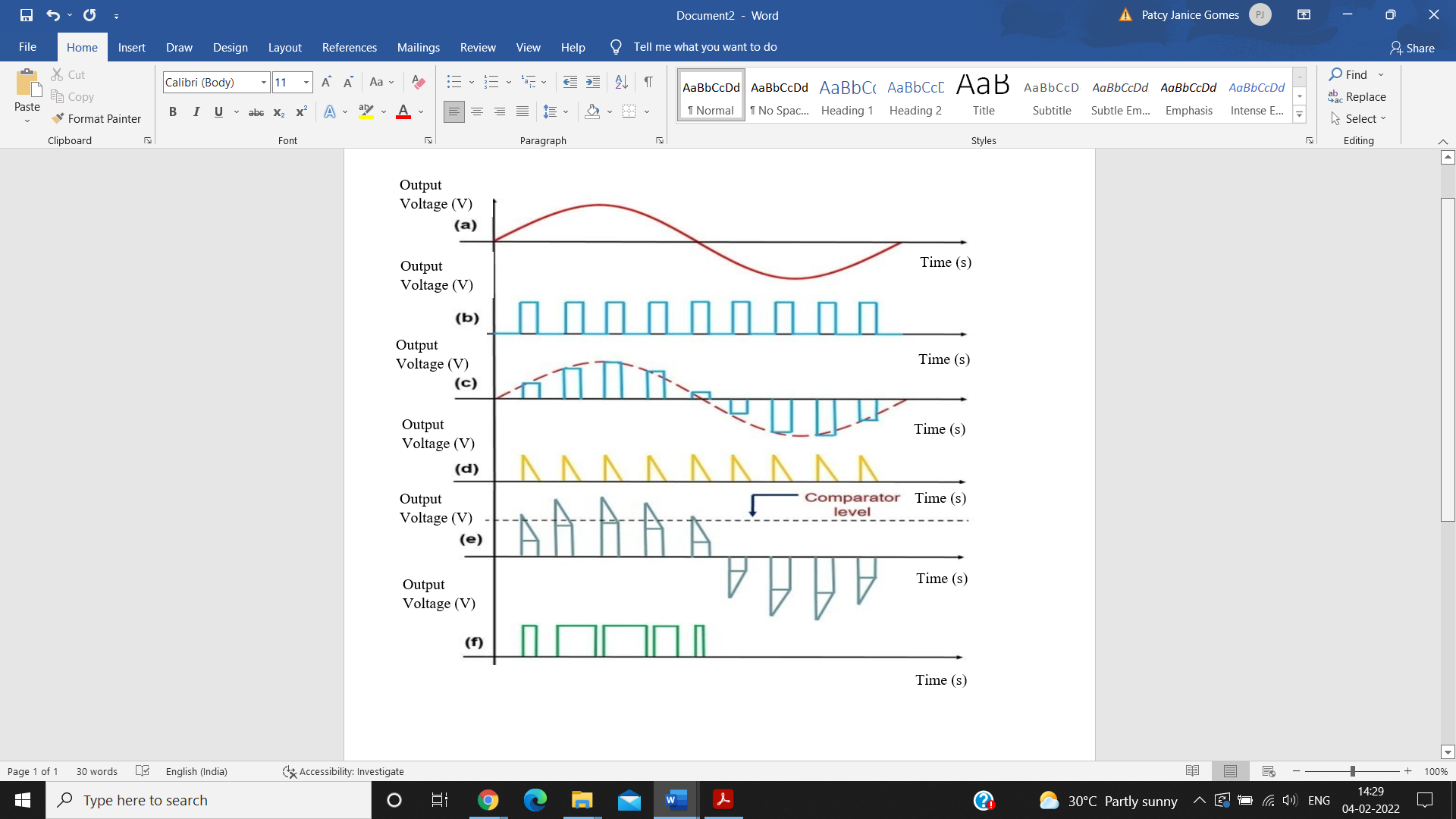
Figure 4. Waveform representation of PWM signal generation. a) Message wave, b) Pulsed carrier, c) Generated PAM wave, d) Comparator output, e) Comparison comparator output with the comparator’s reference voltage and f) Generated PWM waveform.
5. Future directions
Different generators have been presented in existing studies for generating HV pulses and diverse waveforms. Conventionally, Blumlein lines, pulse forming systems and Marx generators were employed for generating HV pulses suitable for PEF and electroporation applications. However, these generators were found to be inefficient, inflexible and bulky. Hence, refined and upgraded generator topologies are desired as existing ones are inappropriate for contemporary applications. For achieving peak power, it is suitable to employ multilevel pulse generator topologies, as the voltage and current stress in devices can be better balanced using these topologies. With respect to pulse regulation, the flexibility which offers independent regulation of every cell also favors the multilevel with huge potential augmentation. Therefore, further research in this direction can be anticipated for future advancements.
To address various bottlenecks encountered in existing designs with respect to pulse generation, research experts started utilizing power electronics concepts and devices for designing generator circuits. Though these circuits produced HV signals, they exhibited lesser effectiveness for electroporation operations. As a result, PWM signals are exploited recently for electroporation owing to their improved features with regard to driving semiconductor power components. Though many PWM waveform generator topologies are available, in majority of them, generation of PWM signals with high power is not addressed. As generation of PWM waveforms with high power is a vital requisite for electroporation functions, better generator circuit topologies are required for achieving this goal. Therefore, further exploration is desired in terms of developing and employing improved PWM generator topologies for generating effective, precise and anticipated PWM signals broadly applicable for electroporation tasks.
6. Conclusion
This review article investigated the existing generator topologies for electroporation signal generation. It explained the significance of PWM signals over HV pulses for electroporation operations. It provided the theoretical background of semiconductor devices and signal generators. This review paper then explored the related studies and reviewed existing circuits and methods for PWM signal generation. The work also presented the circuit for PWM waveform generation. It further identified the chief technical gaps prevailing in this field. Exploring the existing works it was observed that the available signal generator circuits are inflexible and ineffective for electroporation. Moreover, a limited number of circuit topologies for generating high power PWM signals are found. From this review article it could be inferred that better generator circuits capable of generating high power PWM waveforms are desired for achieving better electroporation performance.
References
[1]. Tseng, S.Y., Wu, T.F. and Wu, M.W., 2008. Bipolar narrow-pulse generator with energy-recovery feature for liquid-food sterilization. IEEE Transactions on Industrial Electronics, 55(1), pp.123-132.
[2]. Schoenbach, K. H., Peterkin, F. E., Alden, R. W., & Beebe, S. J. (1997). The effect of pulsed electric fields on biological cells: Experiments and applications. IEEE transactions on plasma science, 25(2), 284-292.
[3]. Raso-Pueyo, J. and Heinz, V. eds., 2010. Pulsed electric fields technology for the food industry: fundamentals and applications. Springer Science & Business Media.
[4]. Qin, B.L., Zhang, Q., Barbosa-Canovas, G.V., Swanson, B.G. and Pedrow, P.D., 1994. Inactivation of microorganisms by pulsed electric fields of different voltage waveforms. IEEE Transactions on Dielectrics and Electrical Insulation, 1(6), pp.1047-1057.
[5]. Jayaram, S.H., 2000. Sterilization of liquid foods by pulsed electric fields. IEEE Electrical Insulation Magazine, 16(6), pp.17-25.
[6]. Moonesan, M.S. and Jayaram, S.H., 2013. Effect of pulsewidth on medium temperature rise and microbial inactivation under pulsed electric field food treatment. IEEE Transactions on Industry Applications, 49(4), pp.1767-1772.
[7]. Elgenedy, M.A., Darwish, A., Ahmed, S. and Williams, B.W., 2017. A transition arm modular multilevel universal pulse-waveform generator for electroporation applications. IEEE Transactions on Power Electronics, 32(12), pp.8979-8991.
[8]. Rocha, L.L., Silva, J.F. and Redondo, L.M., 2014. Multilevel high-voltage pulse generation based on a new modular solid-state switch. IEEE Transactions on Plasma Science, 42(10), pp.2956-2961.
[9]. Elserougi, A.A., Massoud, A.M. and Ahmed, S., 2016. Modular multilevel converter-based bipolar high-voltage pulse generator with sensorless capacitor voltage balancing technique. IEEE Transactions on Plasma Science, 44(7), pp.1187-1194.
[10]. Veilleux, E., Ooi, B.T. and Lehn, P.W., 2013. Marx dc-dc converter for high-power application. IET power electronics, 6(9), pp.1733-1741.
[11]. Sakamoto, T., Nami, A., Akiyama, M. and Akiyama, H., 2012. A repetitive solid state Marx-type pulsed power generator using multistage switch-capacitor cells. IEEE Transactions on Plasma Science, 40(10), pp.2316-2321.
[12]. Rezanejad, M., Sheikholeslami, A. and Adabi, J., 2014. Modular switched capacitor voltage multiplier topology for pulsed power supply. IEEE Transactions on Dielectrics and Electrical Insulation, 21(2), pp.635-643.
[13]. Elserougi, A., Massoud, A.M., Ibrahim, A.M. and Ahmed, S., 2015. A high voltage pulse-generator based on DC-to-DC converters and capacitor-diode voltage multipliers for water treatment applications. iEEE transactions on Dielectrics and Electrical insulation, 22(6), pp.3290-3298.
[14]. Lan, X., Long, M., Zi-jie, X., Qin, X., De-qing, Z. and Zi-kang, Y., 2015. A novel generator for high-voltage bipolar square pulses with applications in sterilization of microorganism. IEEE Transactions on Dielectrics and Electrical Insulation, 22(4), pp.1887-1895.
Cite this article
Ganesan,S.;Taneja,A.;Saluja,N.;Abualigah,L. (2023). Comparison of Different Circuit Topology for Generation of PWM Signal with High Power for Electroporation. Applied and Computational Engineering,8,425-431.
Data availability
The datasets used and/or analyzed during the current study will be available from the authors upon reasonable request.
Disclaimer/Publisher's Note
The statements, opinions and data contained in all publications are solely those of the individual author(s) and contributor(s) and not of EWA Publishing and/or the editor(s). EWA Publishing and/or the editor(s) disclaim responsibility for any injury to people or property resulting from any ideas, methods, instructions or products referred to in the content.
About volume
Volume title: Proceedings of the 2023 International Conference on Software Engineering and Machine Learning
© 2024 by the author(s). Licensee EWA Publishing, Oxford, UK. This article is an open access article distributed under the terms and
conditions of the Creative Commons Attribution (CC BY) license. Authors who
publish this series agree to the following terms:
1. Authors retain copyright and grant the series right of first publication with the work simultaneously licensed under a Creative Commons
Attribution License that allows others to share the work with an acknowledgment of the work's authorship and initial publication in this
series.
2. Authors are able to enter into separate, additional contractual arrangements for the non-exclusive distribution of the series's published
version of the work (e.g., post it to an institutional repository or publish it in a book), with an acknowledgment of its initial
publication in this series.
3. Authors are permitted and encouraged to post their work online (e.g., in institutional repositories or on their website) prior to and
during the submission process, as it can lead to productive exchanges, as well as earlier and greater citation of published work (See
Open access policy for details).
References
[1]. Tseng, S.Y., Wu, T.F. and Wu, M.W., 2008. Bipolar narrow-pulse generator with energy-recovery feature for liquid-food sterilization. IEEE Transactions on Industrial Electronics, 55(1), pp.123-132.
[2]. Schoenbach, K. H., Peterkin, F. E., Alden, R. W., & Beebe, S. J. (1997). The effect of pulsed electric fields on biological cells: Experiments and applications. IEEE transactions on plasma science, 25(2), 284-292.
[3]. Raso-Pueyo, J. and Heinz, V. eds., 2010. Pulsed electric fields technology for the food industry: fundamentals and applications. Springer Science & Business Media.
[4]. Qin, B.L., Zhang, Q., Barbosa-Canovas, G.V., Swanson, B.G. and Pedrow, P.D., 1994. Inactivation of microorganisms by pulsed electric fields of different voltage waveforms. IEEE Transactions on Dielectrics and Electrical Insulation, 1(6), pp.1047-1057.
[5]. Jayaram, S.H., 2000. Sterilization of liquid foods by pulsed electric fields. IEEE Electrical Insulation Magazine, 16(6), pp.17-25.
[6]. Moonesan, M.S. and Jayaram, S.H., 2013. Effect of pulsewidth on medium temperature rise and microbial inactivation under pulsed electric field food treatment. IEEE Transactions on Industry Applications, 49(4), pp.1767-1772.
[7]. Elgenedy, M.A., Darwish, A., Ahmed, S. and Williams, B.W., 2017. A transition arm modular multilevel universal pulse-waveform generator for electroporation applications. IEEE Transactions on Power Electronics, 32(12), pp.8979-8991.
[8]. Rocha, L.L., Silva, J.F. and Redondo, L.M., 2014. Multilevel high-voltage pulse generation based on a new modular solid-state switch. IEEE Transactions on Plasma Science, 42(10), pp.2956-2961.
[9]. Elserougi, A.A., Massoud, A.M. and Ahmed, S., 2016. Modular multilevel converter-based bipolar high-voltage pulse generator with sensorless capacitor voltage balancing technique. IEEE Transactions on Plasma Science, 44(7), pp.1187-1194.
[10]. Veilleux, E., Ooi, B.T. and Lehn, P.W., 2013. Marx dc-dc converter for high-power application. IET power electronics, 6(9), pp.1733-1741.
[11]. Sakamoto, T., Nami, A., Akiyama, M. and Akiyama, H., 2012. A repetitive solid state Marx-type pulsed power generator using multistage switch-capacitor cells. IEEE Transactions on Plasma Science, 40(10), pp.2316-2321.
[12]. Rezanejad, M., Sheikholeslami, A. and Adabi, J., 2014. Modular switched capacitor voltage multiplier topology for pulsed power supply. IEEE Transactions on Dielectrics and Electrical Insulation, 21(2), pp.635-643.
[13]. Elserougi, A., Massoud, A.M., Ibrahim, A.M. and Ahmed, S., 2015. A high voltage pulse-generator based on DC-to-DC converters and capacitor-diode voltage multipliers for water treatment applications. iEEE transactions on Dielectrics and Electrical insulation, 22(6), pp.3290-3298.
[14]. Lan, X., Long, M., Zi-jie, X., Qin, X., De-qing, Z. and Zi-kang, Y., 2015. A novel generator for high-voltage bipolar square pulses with applications in sterilization of microorganism. IEEE Transactions on Dielectrics and Electrical Insulation, 22(4), pp.1887-1895.