


1. Introduction
People are increasingly in need of fresh energy, particularly for energy storage, as a result of the ongoing depletion of main energy sources like fossil fuels and the greenhouse effect, which is becoming more severe. Electric vehicles have evolved and are starting to replace conventional gasoline vehicles gradually in an effort to solve the energy dilemma. Electric vehicles have lower average maintenance costs and cost less to travel the same distance than fuel-powered vehicles [1]. Additionally, an electric car's torque is quite high when it is launched, and the electric motor will provide the vehicle with powerful acceleration when it is moving at a low speed. This is groundbreaking because gasoline-powered cars accelerate more slowly than electric ones. The electric motor runs silently without making any audible noises or obvious bumps. Battery technology is the fundamental component of electric vehicles, and lithium-ion batteries, an emerging technology, are increasingly frequently used in electric vehicle batteries. The most developed and often used energy storage battery at this time is the lithium-ion battery (LIB) with high energy density. It is commonly used in both vehicles (electric automobiles, electric motorcycles, etc.) and portable electronic gadgets. Lithium-ion batteries have many benefits over conventional batteries (like zinc-manganese batteries). It can retain a steady capacity even after thousands of charge and discharge cycles, and it has the highest energy density (450 Wh/kg) [1, 2]. Its superior electrochemical features also include little irreversible energy loss and a comparatively low volume expansion coefficient. LIBs have gained popularity in recent years and are the subject of an increasing number of studies due to their availability and ease of lithium extraction.
Scientists have long concentrated their research on the anode of lithium-ion batteries because optimizing the lithium content of the anode within a constrained volume is essential to LIB performances. Graphite is a readily available, affordable negative electrode material that is now used as the negative electrode in lithium-ion batteries [1, 3]. Graphite has high conductivity, and LiC6 is typically formed by adding one lithium atom to six carbon atoms. The LiC6 has a volumetric capacity of 719 Ah L-1 and a gravimetric capacity of 372 mAh g-1, which does not represent a high capacity, and lithium deposition occurs [4]. Researchers looked to silicon to help them tackle the graphite anode issue. Currently, Si is regarded as a desirable option for anode materials. For every silicon atom, there may be more lithium atoms. At room temperature, it has a fully lithiated Li15Si4 and incredibly high gravimetric (3579 mAh g-1) and volumetric (2190 mAh cm-3) capacities, which is more than ten times that of graphite anode (372 mAh g-1) [1]. An interesting point is that its operating voltage (0.4 V vs. Li/Li+) is also higher than that of graphite, which is more suitable for those high-energy batteries. Like graphite, silicon is easy to mine and process, giving silicon a low price.
Similar to the silicon anode, the silicon anode has its own issues as well, making it difficult to use on a big scale and keeping it at the experimental stage. The conductivity of silicon is quite low (10-3 S /cm) compared to the high conductivity of graphite, which makes it challenging for current to flow on silicon. In addition, lithium has a low diffusion efficiency on silicon (between 10-14 and 10-13 cm2 s-1), which makes it challenging to transport lithium ions efficiently. Most notably, silicon anodes are extremely prone to swell (>280%), and their unavoidable dramatic volume changes throughout the lithiation-delithiation process would result in the continual creation of solid electrolyte interface (SEI) layers and the desorption of active components (as shown in Figure 1) [1]. The SEI layer is continuously fractured and reformed, triggering irreversible capacity loss [1]. For these extreme changes and defects, only through continuous improvement of structure and components can a suitable solution be found.
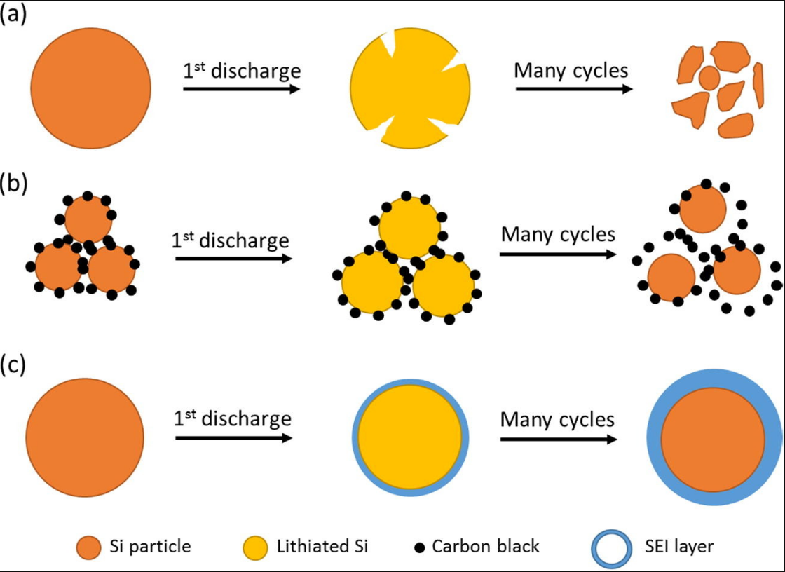
Figure 1. The failure mechanism of a Si anode (a) pure Si particles, (b) Si particles with carbon black, (c) Si particles with SEI layer [1].
The explosive growth of nanotechnology since the turn of the century has given silicon anodes hope. Through research, it has been found that reducing the size of silicon can well solve some of the above-mentioned problems. To achieve a better contact effect, such as between electrodes or the contact between the electrodes and the electrolyte, etc., the so-called nanotechnology involves shrinking the size of the material to the nanometer level. This increases the surface area of the same quality material and the area in contact with the outside world. At the same time, silicon volume growth caused by the spaces between nanoparticles can be successfully eliminated by nanotechnology [2]. Si nanoparticles, nanowires, nanotubes, flakes, nanopillars, and Si with nanoporous architectures are examples of these nanosized silicon materials at the moment [3,4]. This article will cover the principles, experimental preparation and characterization, and performance testing for nanoparticles and nanowire structures through specific experiments.
2. Si nanoparticles (NPs)
2.1. Pure NPs
The nanoparticle is the most prevalent nanostructure and is also the easiest to reach structure. Pure silicon nanoparticles are produced via an extremely sophisticated method. The pure nano-Si particle anode demonstrates remarkable performance, with large capacitance and strong cycle stability thanks to the nanostructure, which allows the interstitial space between Si NPs to suppress volume expansion and decrease the diffusion length of lithium ions. It is a silicon anode material that is still fairly advanced. The manufacturing of pure silicon nanoscale anodes will then be made simple and effective [5].
A typical process for making organosilane monomers involves reacting silicon with hydrogen chloride gas under the catalysis of nano-copper-based catalysts. However, during the reaction process, the remaining silicon will continue to fragment and disintegrate, and the size will continue to shrink, which provides an opportunity for the nanonization of silicon.
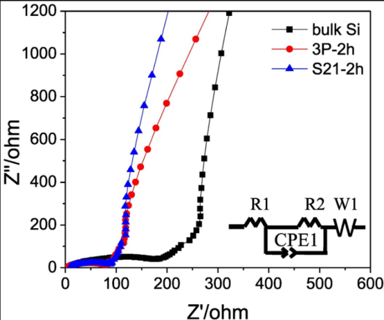
In order to obtain pure silicon nanoparticles, Takeshi Wada et al. generated a mixture of the copper-based catalyst using ball milling, then removed the copper-based catalyst using acid pickling [5]. It was found that Si NPs between 100 and 300 nm in size were linked [5]. At a current of 50 mA/g, they compared the Coulombic efficiency (CE) and discharge capacity of silicon nanoparticles catalyzed by two copper-based catalysts, 3P-2h (a catalyst made up of copper, copper oxide, and copper dioxide), and S21-2h (a catalyst made up of copper dioxide). The findings demonstrated that whereas nano-silicon has always demonstrated greater discharge capacity, the discharge capacity of bulk silicon drastically decreases after 10 cycles. Figure 2 and 3 demonstrates that nano-silicon has consistently exhibited a higher CE than bulk silicon, highlighting the strong electrochemical performance of nano-silicon particles [5]. Notably, the resistance of nanoparticles was observed to be lower than that of bulk silicon. Specifically, bulk Si maintained a minimum resistance of 193 Ω, whereas the sample 3P-2h and S21-2h exhibited resistance values of 80 Ω and 88 Ω, respectively. The authors of the study suggest that the larger specific area of nano-silicon results in a shorter distance for ion conduction and the weakened expansion effect of silicon at the nanometer scale [5]. Overall, these findings underscore the promising potential of nano-silicon in various applications and warrant further research in the field.
|
|
Figure 2. Cycling properties and CE at 50 mA g−1 [5]. | Figure 3. Electrochemical impedance plots [5]. |

2.2. Silicon/carbon nanofiber/graphene composite films
Additionally, silicon nanoparticles can be combined with other substances to create composite materials that play to each component's advantages. Currently, a composite film made of Si, C nanofibers, and graphene (Si/CNF/rGO) has been created by Ruye Cong et al., using silicon nanoparticles to primarily absorb lithium, carbon nanofibers to support the force to reduce Si volume expansion, and graphene to improve the low electrical conductivity of Si, resulting in excellent electrochemical performance [6]. The process for producing concrete was depicted in Figure 4. The composite films with various ratios and films devoid of carbon nanotubes had various cycle performances at 0.1 A/g, as shown in Figure 5. Si/rGO's cycle performance declined much more quickly than other anode materials with CNFs because silicon's volume growth was more difficult to control with just graphene. As demonstrated in Figure 6, the cycle performance varied significantly for various Si/CNF/rGO ratios. Poor cycle stability was caused by the fact that Si NPs tend to agglomerate. When the ratio was 1:1, nanofibers were able to completely enclose nano-silicon particles, successfully preventing their volume expansion and maintaining good cycle stability. After 50 cycles and 100 cycles, the resistance values of the two electrodes did not significantly change, demonstrating the electrode's high degree of stability [6].
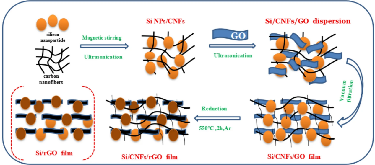
Figure 4. The manufacturing process of Si/CNF/rGO [6].
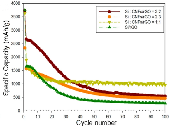
Figure 5. Cycling performances of Si/rGO and Si/CNF/rGO = 1:1, 2:3, and 3:2 at 0.1 A/g [6].
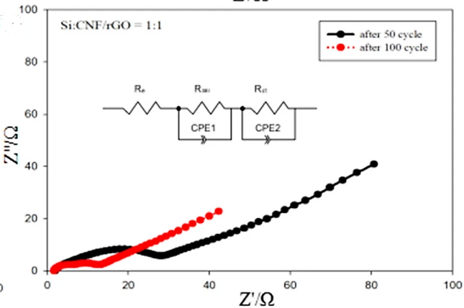
Figure 6. the Nyquist plot of Si/CNF/rGO=1:1 sample [6].
2.3. Si@void@C/CNFs
In order to prevent Si NP volume expansion, Xilei Xie et al. produced yolk-shell Si@void@C NPs, linking the composite nanoparticles to the carbon nanotube network in order to increase conductivity and flexibility. First, a coating of silicon dioxide was formed by hydrolyzing the nanoparticles with tetraethoxysilane (TEOS), and then a layer of carbon was added by carbonizing resorcinol formaldehyde. The silicon dioxide layer was next etched using hydrofluoric acid to create a hollow layer, and then Si@void@C was electronically spun into a bond with the carbon nanotube network to create Si@void@C/CNFs. The specifics are displayed in Figure 7 [7].
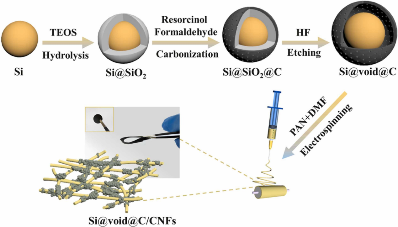
Figure 7. The manufraturing process of Si@void@C/CNFs [7].
It was found that the shape was spherical particles linked to the fiber surfaces [7].
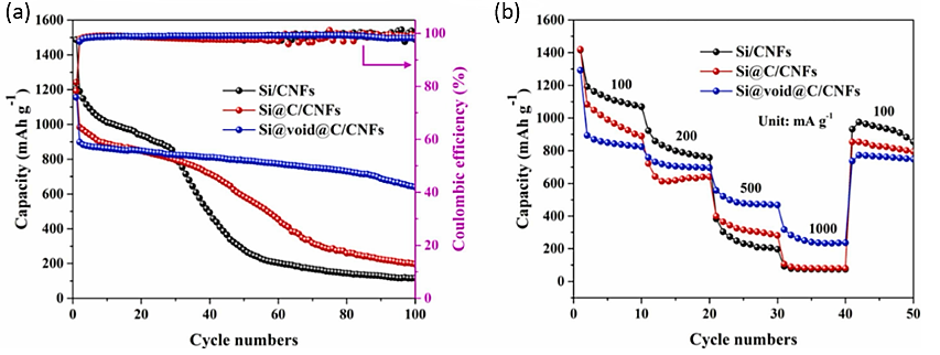
Figure 8. The electrochemical analysis of Si@void@C/CNFs anode (a) Cycle performance and (b) rate curves [7].
The electrode performed electrochemically extraordinarily well. Due to the decreased silicon concentration, as seen in Figure. 8, the Si@void@C/CNFs electrode's initial discharge capacity was 1193.8 mAh /g. However, after 100 cycles, it still had an astounding 69.3% retention rate and a capacity of 627.5 mAh /g. According to the rate curve, the electrode had a capacitance that was much larger than that of other electrodes when the current was 100, 200, 500, and 1000 mA, respectively [7].
2.4. Si//PCNF-15
Hao Wang et al. discovered a method to uniformly disperse silicon nanoparticles into CNFs and fabricated a novel Si//PCNF-15 electrode. The homogeneous elemental nano-Si particles significantly improved the stability of the SEI film, while the porosity and ductility of CNFs also provided a buffer for the expansion of Si particles, and the film of the whole material exhibited extremely strong self-standing and flexibility [8].
Fabrication of such composites requires the use of electrospinning (Figure 9). Silicon nanoparticles/PAN/P123 were electrospun to make composite fiber precursors, in which P123 (polyethylene oxide-polypropylene oxide-polyethylene oxide triblock copolymer) was used as a pore-directing agent and a dispersant. After peroxidation and carbonization, PAN was changed into carbon fiber to obtain Si//PCNF-15 electrode. Accroding to SEM images, it was found that the diameter of the synthesized carbon fiber was 300-400 nm, and the silicon nanoparticles were all wrapped by a carbon shell of about 10 nm [8].
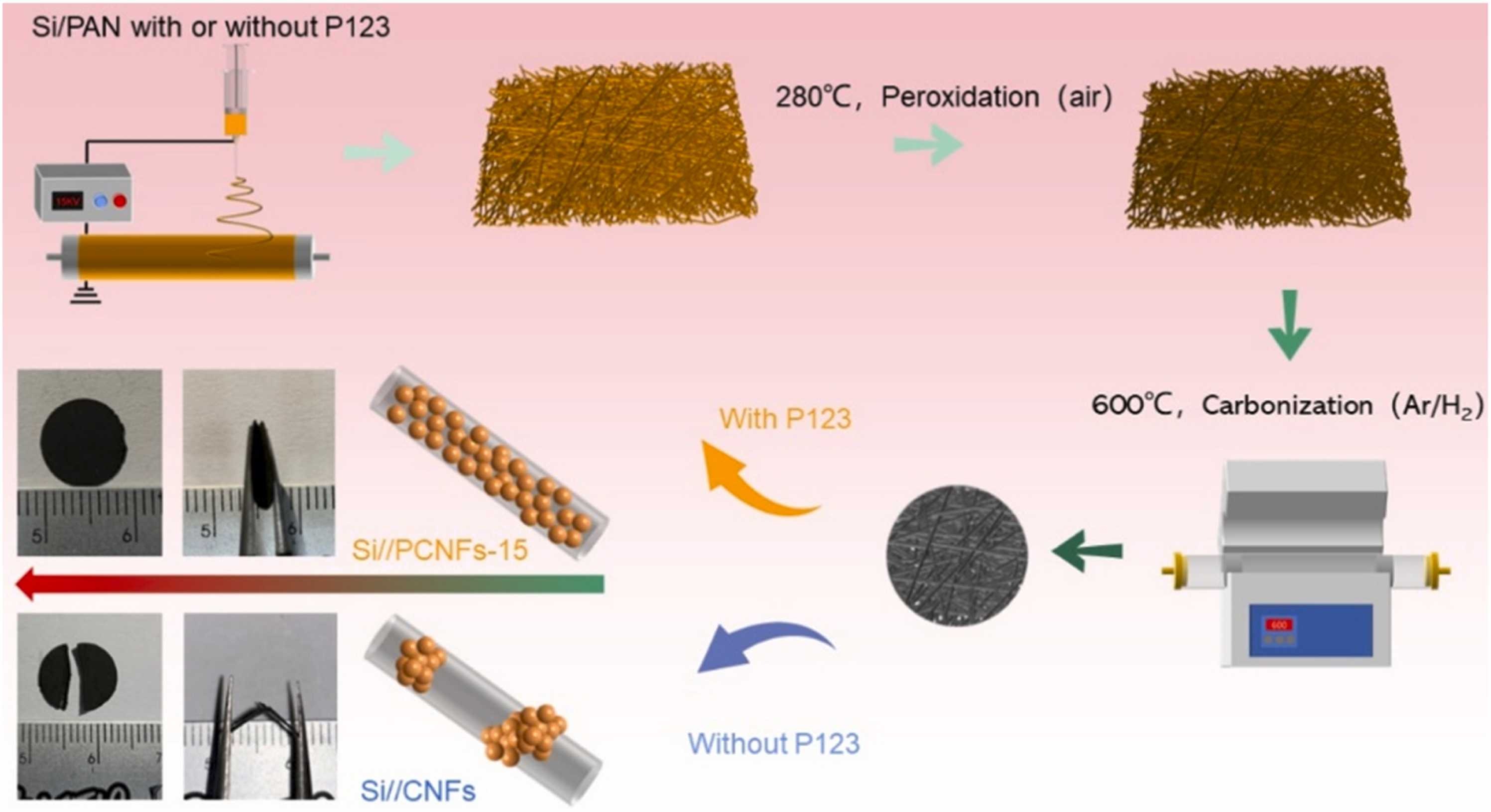
Figure 9. The manufacturing process of Si//PCNF-15 [8].
Electrochemically, the electrode performed excellently. The cycle performance and rate curve of the electrode can be seen from the Figure 10. Even after 250 cycles, the Si//PCNF-15 electrode still maintained a reversible capacity of 1063.2 mAh/g, with an average CE of 99.3%. Meanwhile, the reversible capacities of the electrode were 1579, 1452, 1285, 1099.9, 435.9 and 236.1 mAh /g at current densities of 0.1, 0.2, 0.5, 1, 2, 5 and 10 A /g, respectively, proved to be a stable and efficient electrode [8].
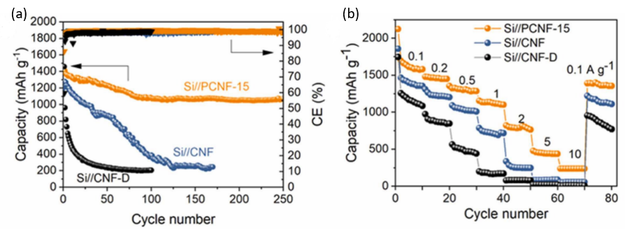
Figure 10. The electrochemical analysis of Si//PCNF-15 anode (a) Cycle performance and (b) rate curves [8].
3. Si wires (NWs)
3.1. Pure NWs
One of the most important one-dimensional materials is silicon nanowires, as opposed to silicon nanoparticles. Amprius has just finished producing its first batch of lithium batteries, which have a much higher energy density (450 Wh/kg) than Tesla's batteries. It also has a lightning-fast charging rate and can charge up to 80% of its capacity in six minutes. Silicon nanowires have an advantage over nanoparticles in that they can more easily release stress through axial expansion due to their characteristic linear structure.
Direct growing of dense intra-seeded Si NWs on 3D copper silicide (3D-CS)-based CCs is one method of fabricating silicon nanowires. Thermal evaporation and seed deposition techniques were used to construct 3D-CS networks (Cu-Silcon compound) on the surface of copper foils in Figure 11. Then, silylbenzene solution was applied to the in@3D-CS substrate to create the Si NW network [9]. The densely woven Si NWs was efficiently encouraged to grow by the high seed loading on the substrate [9]. Si NWs@3D-CS exhibited exceptionally high cycle stability. In contrast to many silicon electrodes, Figure 12 shows that the electrode may nevertheless maintain a strong volumetric discharge capacity at various rates [9].
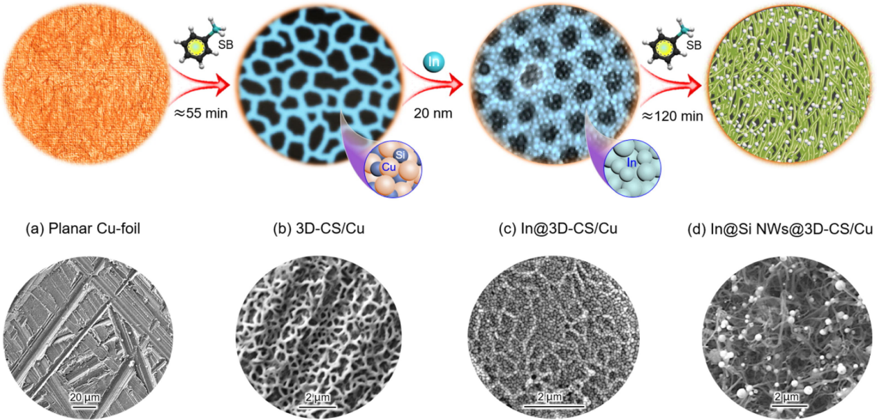
Figure 11. Schematic diagram of the synthesis of interwoven seeded Si NWs@3D-CS network electrodes.
3.2. Si@C-Cu Composite NWs
Nanowires can also be made into composite materials. The researchers found that silicon nanowires can be coated with carbon to prevent the volume expansion. At the same time, metal nano atoms such as copper can be embedded in silicon nanowires to enhance conductivity.
In Figure 12, homogeneously mixed solutions of copper acetate and glucose were displayed with pure sub-micron Si particles that had a layered structure. To obtain the precursor, combine the ingredients, then heat the ultrasonic autoclave to a high temperature of 190 degrees Celsius. After cooling, filter, wash, and dry the mixture, Si@C–Cu composite NWs (Si@C–Cu–HT) were produced after cooling [10]. Figure 13 displayed the three electrodes' capacity and CE for a constant current. After repeated cycling, the capacitance of Si@C and Si@C-LT drastically dropped, whereas Si@C-HT shown good stability. The continual variation in the silicon volume that is not completely encapsulated in the former is what led to this disparity. However, the coulombic efficiencies of all three were close to 100%, which means that all three electrodes had good reversibility [10].
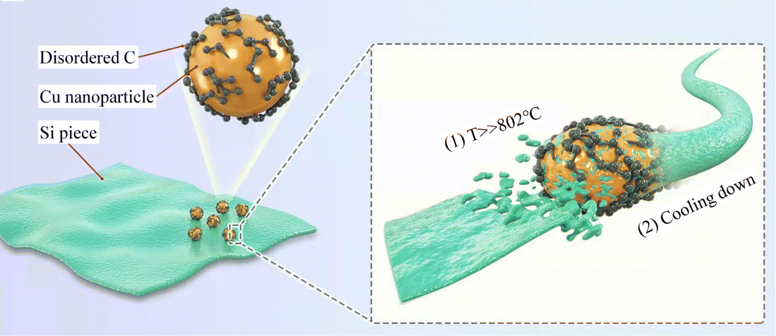
Figure 12. The formation mechanism of Si@C-Cu Composite NWs [10].
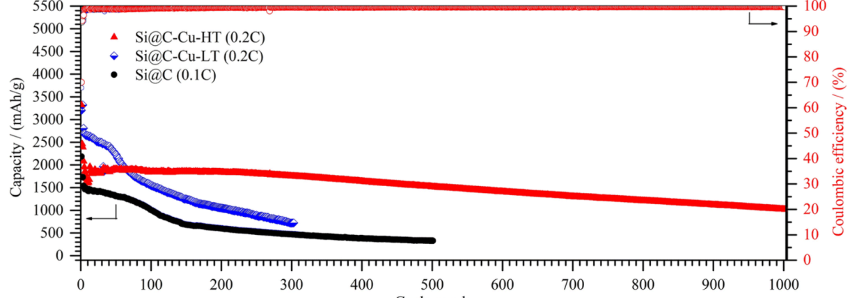
Figure 13. Galvanostatic charge/discharge performances [10].
3.3. pSi-NWs@c-Cs
Fangfang Zhang et al. prepared a silicon nanowire pSi-NWs@c-Cs containing intersecting carbon framework, in which the carbon framework covered the surface and pores of the nanowire. This structure can effectively improve the conductivity of the electrode and shorten the lithiation/delithiation route. In addition, the attached carbon shell can effectively stabilize the SEI layer and avoid its repeated formation to reduce the effective content of lithium [11].
Si-NWs were first prepared using metal-assisted chemical etching (MACE), and after that, a vacuum annealing step using a tiny carbon source like hydroquinone-formaldehyde resin (RF) produced a carbon layer that covered the surface and the pores. Figure 14 depicted the precise synthesis procedures for pSi-NWs@c-Cs. A 30–40 nm carbon layer was found to have developed on the silicon nanowire's surface and inside its hole [11].
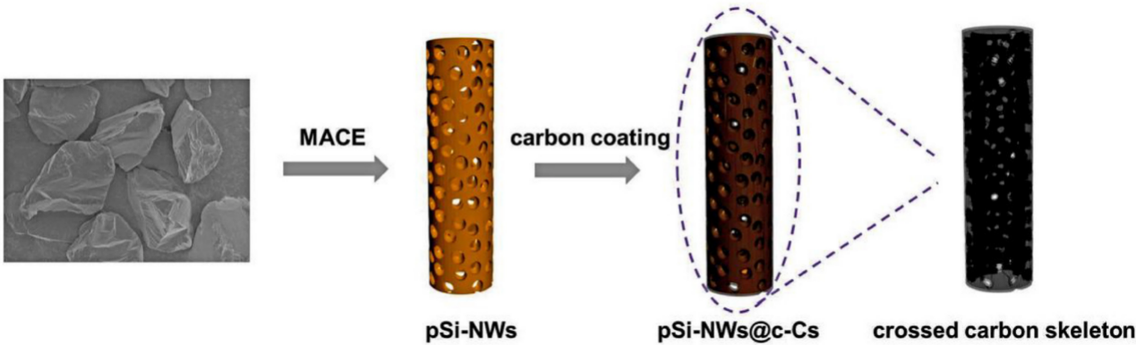
Figure 14. The manufacturing process of Si//PCNF-15 [11].
Owing to the various advantages mentioned above, the electrode exhibited good electrochemical performances. After 100 cycles, the specific capacity and CE of pSi-NWs@c-Cs could still maintain 1000 mAh /g and 75%. According to the rate diagram (Figure 15), it could be seen that the specific capacity was higher than that of pSi-NWs@rGO at 0.2, 0.4, 0.8, 1.0, 2.0, and 4.0 mA g-1 [11].
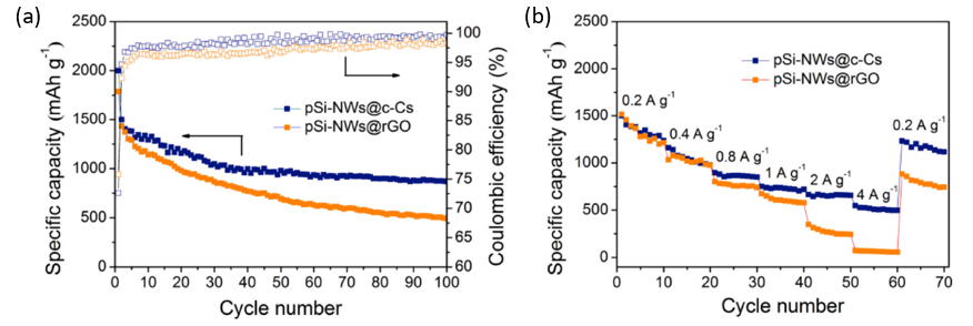
Figure 15. The electrochemical analysis of pSi-NWs@c-Cs anode (a) Cycling properties, CEs and (b) rate performances [11].
3.4. Au-SiNWs/G
Han-Jung Kim et al. prepared an Au-SiNWs/G thin film anode material. Inside this material, silicon nanowires were entangled with one another to obtain a nanonetwork, and graphene flakes and gold particles were used as binders and conductive additives, which effectively alleviated the volume expansion of silicon nanowires and enhance conductivity. In order to prepare this composite film, the manufacturing process was shown in Figure 16, Si NWs were etched by MACE, then Au nanoparticles were deposited on the film, and finally Au-SiNWs/G film was prepared by hot pressing. All Si NWs were well-wrapped by graphene flakes and Au NPs [12].
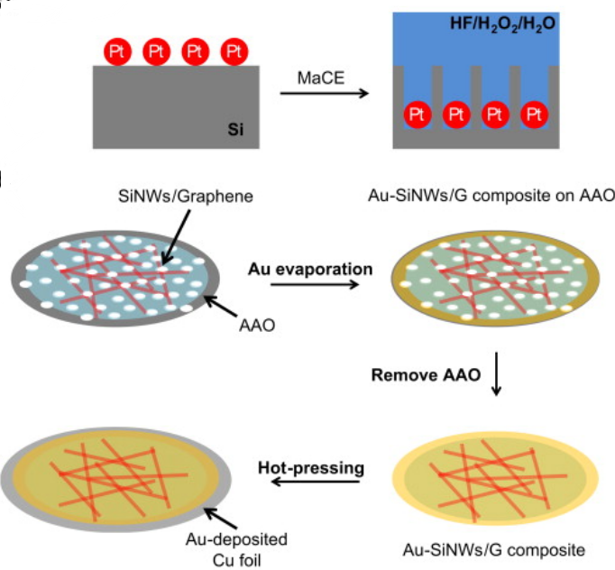
Figure 16. The manufacturing process of Au-SiNWs/G film [12].
Due to the introduction of graphene and gold particles, the electrode had excellent electrochemical performance. As shown in Figure 17 (left), the original discharge capacity was 2210 mA h/g, and the reversible charge capacity was 1250 mA h/g. At the same time, it could be seen from the Figure 17 (right) that the reversible capacity could reach 1520 mA h/g even after twenty cycles, which was much higher than that of other electrodes [12].
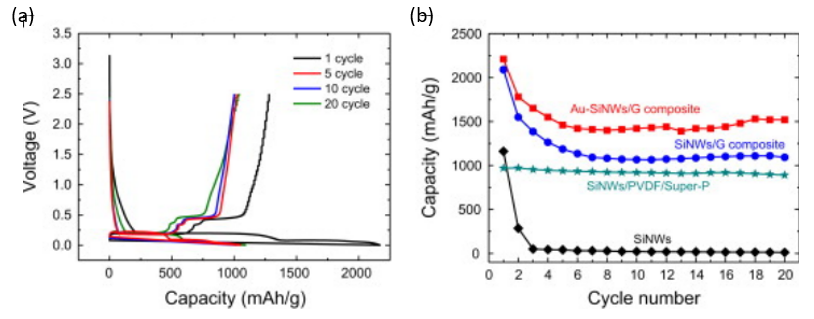
Figure 17. The electrochemical analysis of Au-SiNWs/G thin film anode (a) Galvanostatic charge/discharge profiles; (b) The cycling properties [12].
4. Conclusion
Two common nano-silicon electrodes are introduced in this article: silicon nanoparticle electrodes and silicon nanowire electrodes. For each electrode, there are pure electrodes and composite electrodes. The article begins with the production process and electrochemical performance in order to thoroughly introduce each electrode. In order to obtain reasonably high power and stability, the silicon anode needed support from the present nanotechnology to solve issues like volume expansion, reducing the path of lithiation, improving conductivity, etc. However, there are other restrictions to nanotechnology as well, which hinder the creation of silicon anodes. Currently, it is challenging to deploy nanotechnology on a wide scale in the field of lithium batteries due to the technology's relatively high cost and intricate manufacturing procedure. However, it is anticipated that these limitations will not last very long. Nano-silicon electrodes have demonstrated tremendous potential so far, and it is anticipated that they will soon displace graphite electrodes as the primary electrode material for lithium-ion batteries.
References
[1]. Xu, Z.-L., et al., 2017. Progress in Materials Science, 90: 1-44.
[2]. Zhao, X. and V.-P. Lehto, 2021 Nanotechnology, 32(4): 042002.
[3]. Jang, J., et al., 2020 Chemical Engineering Journal, 401: 126091.
[4]. Wada, T., Yamada J., et al. 2016 Journal of power sources, 306: 8-16
[5]. He, Q., et al., 2018 Solid State Ionics, 325: 141-147.
[6]. Cong, R., et al., 2021. Scientific Reports, 11(1): 1283.
[7]. Xie, X., et al., 2023 Journal of Alloys and Compounds, 931: 167473.
[8]. Wang, H., et al., 2023 Colloids and Surfaces A: Physicochemical and Engineering Aspects, 671: 131653.
[9]. Saana Amiinu, I., et al., 2023 Journal of Energy Chemistry, 81: 20-27.
[10]. Chen, S., et al., 2022 Sustainable Energy & Fuels, 6(21): 4991-4999.
[11]. Zhang, F., et al., 2018Electrochimica Acta, 280: 86-93.
[12]. Kim, H.-J., et al., 2014 Physica E: Low-dimensional Systems and Nanostructures, 61: 204-209.
Cite this article
Han,R. (2023). Si nanomaterials in lithium-ion battery anode. Applied and Computational Engineering,26,62-72.
Data availability
The datasets used and/or analyzed during the current study will be available from the authors upon reasonable request.
Disclaimer/Publisher's Note
The statements, opinions and data contained in all publications are solely those of the individual author(s) and contributor(s) and not of EWA Publishing and/or the editor(s). EWA Publishing and/or the editor(s) disclaim responsibility for any injury to people or property resulting from any ideas, methods, instructions or products referred to in the content.
About volume
Volume title: Proceedings of the 2023 International Conference on Functional Materials and Civil Engineering
© 2024 by the author(s). Licensee EWA Publishing, Oxford, UK. This article is an open access article distributed under the terms and
conditions of the Creative Commons Attribution (CC BY) license. Authors who
publish this series agree to the following terms:
1. Authors retain copyright and grant the series right of first publication with the work simultaneously licensed under a Creative Commons
Attribution License that allows others to share the work with an acknowledgment of the work's authorship and initial publication in this
series.
2. Authors are able to enter into separate, additional contractual arrangements for the non-exclusive distribution of the series's published
version of the work (e.g., post it to an institutional repository or publish it in a book), with an acknowledgment of its initial
publication in this series.
3. Authors are permitted and encouraged to post their work online (e.g., in institutional repositories or on their website) prior to and
during the submission process, as it can lead to productive exchanges, as well as earlier and greater citation of published work (See
Open access policy for details).
References
[1]. Xu, Z.-L., et al., 2017. Progress in Materials Science, 90: 1-44.
[2]. Zhao, X. and V.-P. Lehto, 2021 Nanotechnology, 32(4): 042002.
[3]. Jang, J., et al., 2020 Chemical Engineering Journal, 401: 126091.
[4]. Wada, T., Yamada J., et al. 2016 Journal of power sources, 306: 8-16
[5]. He, Q., et al., 2018 Solid State Ionics, 325: 141-147.
[6]. Cong, R., et al., 2021. Scientific Reports, 11(1): 1283.
[7]. Xie, X., et al., 2023 Journal of Alloys and Compounds, 931: 167473.
[8]. Wang, H., et al., 2023 Colloids and Surfaces A: Physicochemical and Engineering Aspects, 671: 131653.
[9]. Saana Amiinu, I., et al., 2023 Journal of Energy Chemistry, 81: 20-27.
[10]. Chen, S., et al., 2022 Sustainable Energy & Fuels, 6(21): 4991-4999.
[11]. Zhang, F., et al., 2018Electrochimica Acta, 280: 86-93.
[12]. Kim, H.-J., et al., 2014 Physica E: Low-dimensional Systems and Nanostructures, 61: 204-209.