


1. Introduction
FORMULA ONE originated in Europe in the 1920s. It is now one of the most technology-driven sports. The development of F1 radiates to all other industries for its incredible innovation in engines, tires, materials, and aerodynamic designs. This study aims to understand the physics and implementation of F1 cars’ aerodynamic designs. A modern F1 racing car can accelerate from 0 to 60 in 2.6 seconds with a top of 230 mph [1]. The take-off speed of a Boeing 737 is around 150-180 mph [2]. Therefore, creating sufficient downforce, maximum stability and speed are the three primary considerations when designing an F1 racing car. The main parts that will analyze in this study are the front wing, rare wing, diffuser, bargeboards, and S-Duct. Understanding how these components complement each other can inspire other industries like high-speed trains and aeromobil.
2. General purposes of F1 parts related to aerodynamic performance
2.1. Creating downforce
Downforce is one of the most critical parameters for an F1 open-wheel racing car, along with power, weight, and tires [3]. The rare wing is the main part that creates the most downforce where the air near the bottom surface of the wing flow must faster than that on the top surface. The nonsymmetrical airfoil in the rare wing is similar to what is shown in Figure 1, where the end tip is tilted up at an angle. According to Bernoulli's effect and equation (1), the faster the velocity of the flow, the lower the pressure [4]. Therefore, due to the flow velocity difference between the top and bottom surface, the air pressure on the top surface is larger than that on the bottom, which creates downforce. Moreover, the end tip of the airfoil is tilted upward. According to Newton's Third Law, there is an equal and opposite force exerted back for every force exerted on an object. This law is also applied to tilting in the airfoil, in which the tilting part pushes the air upwards, and therefore the air pushes the airfoil downwards.
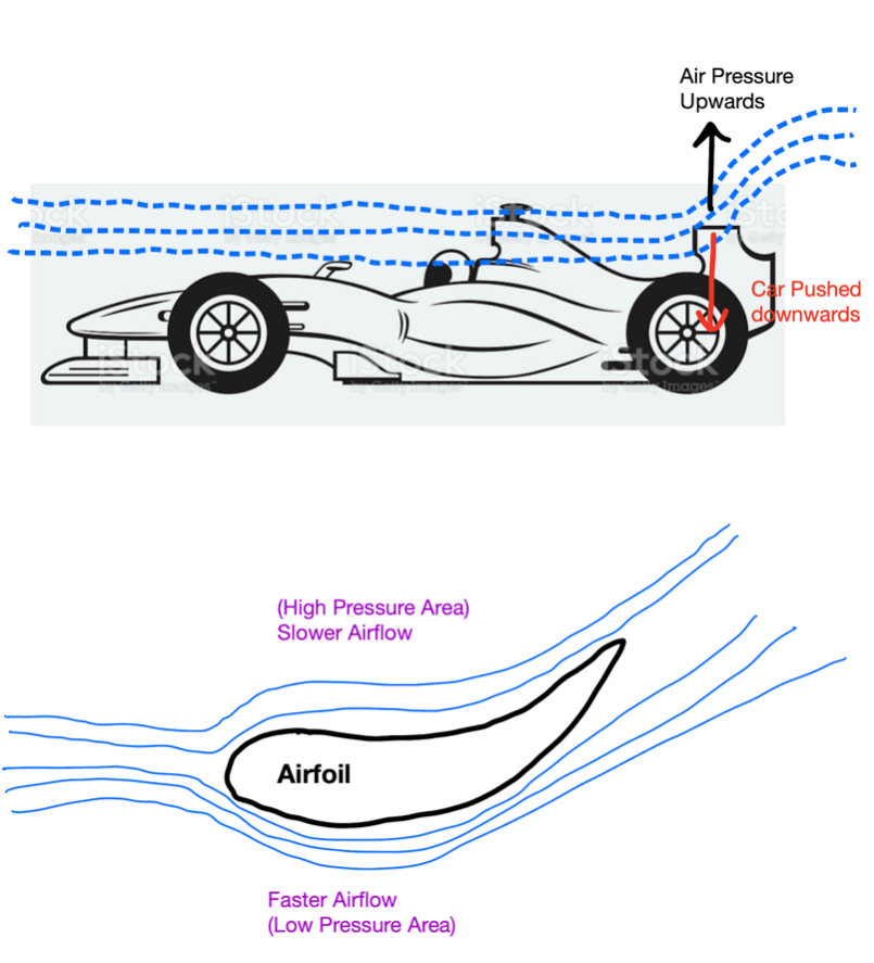
Figure 1. Basic Model of Airfoil in F1’s Rare Wing.
\( P+\frac{1}{2}ρ{V^{2}}=Constant \) (1)
2.2. Creating vortices
Turbulence is the main factor that decreases the instability of F1 cars. One of the main sources is the low-pressure area created by the car in front of another, which is also called the "dirty air" [5]. The other source comes from the airflow velocity relative to the car's surface; and the airfoils' angle of attack. When the airflow velocity is too high or the angle of attack exceeds the critical number, the molecular force between the air molecules can no longer hold the airflow attached to the surface. In this situation, the airflow is separated, as shown in Figure 2. Between the boundary layer and the separated layer, turbulence is created. And this turbulence would decrease the stability and downforce of the car. In order to eliminate this turbulence, vortices can be used to drag the boundary layer and the separated flow together, as shown in Figure 3 [6].
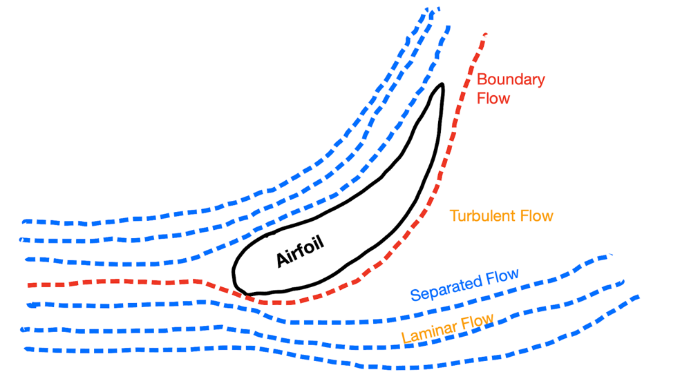
Figure 2. Separation of Airflow in Airfoil Example.
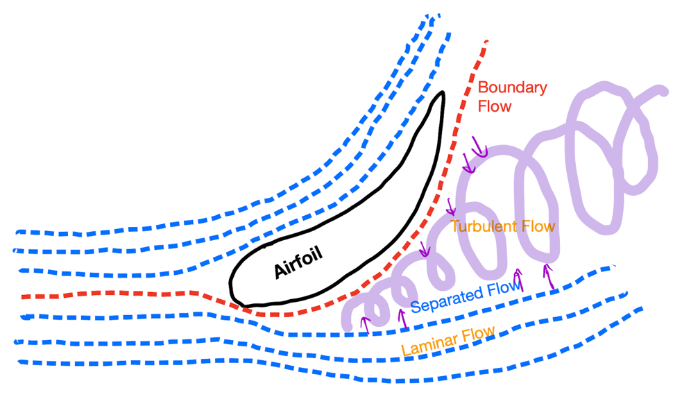
Figure 3. Vortex Implantation in the Separated Airflow.
3. Individual parts analysis
3.1. Front wing
The two main purposes of the front wings are creating downforce in the frontal axis and vortices to direct the airflow. Since the front wing is the first part that makes contact with the airfoil, it becomes crucial for shaping the airflow intacts with other parts of the aerodynamic design [7]. The front wing produces about 40 percent of the downforce for the car. As shown in FIG 4, the front wing contains multiple profiles. Both main planes and spoilers serve the purpose of creating downforce as their shapes are similar to the airfoil discussed in the previous section. They also force the airflow upwards to go onto the car's surface, also called an upwash. The spoilers' edges, close to the center of the car, is shown in FIG 5. Due to the pressure difference between the top and bottom planes, the wing tip effects create circulations; therefore, by carefully constructing the angles, they create vortices. With multiple tipped edges, the vortices add up and become more energetic. These vortices drag the upwash symmetrically close to the surface of the car. The endplates on the sides of the front wing are responsible for diverting the airflow away from the front wheels to reduce the turbulence created by the opened spinning wheels. The thermal camera monitors the temperature of the front tires, and the incidence modifier allows drivers to adjust car's understeer and oversteer levels. The effect diagram is shown in FIG 6, where one can see that it shapes the airflow to a wanted situation as mentioned earlier.
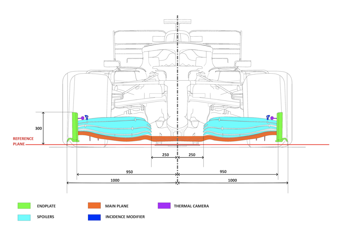
Figure 4. Components of F1 Front Wing [7].
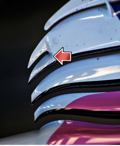
Figure 5. Edges of the spoilers to the center [7].
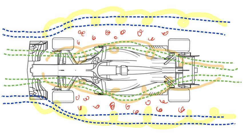
Figure 6. The Effect of the Front Wing.
3.2. Rare wing
The rare wing locates at the rare end of the car and is composed of 5 parts, including the main plane, a flap, two endplates, two middle trims, and two bottom trims, which are shown in number order in FIG 7. This construction provides up to 20 percent of the total downforce generated by the car [7]. The main function of this part is to counterbalance the downforce produced by the front wing [8]. The main plane and flap contribute the most to creating the needed downforce. However, without the other components, it creates drag on the car. The model of the single plane system is shown in FIG 8. Without other components, the edges of the main plane and flap generate vortices due to the wingtip effect. The vortices circulate towards the outside of the car. This turns some of the backward airflow energy into sideway spiral energy. And according to Newton's Third Law, if some force slows down the speed of airflow, there would be an opposite force slowing the car down, which is the drag. In order to eliminate this drag, the endplates were designed. There are two designs in the endplates, louvers and a cutout. The louvers are the set of opened cuts where the number 3 left arrow indicates, and the "cutout" is what the right arrow indicates. The louvers allow air to flow from the high-pressure area, which is the main plane and the flap, to the low-pressure area to the side of the car. This reduces the pressure difference between two areas and the vortices' strength. Now, both sides of the endplates experience high-pressure airflows. Therefore, both airflows generate a vortex at the "cutout" in different directions and cancel out with each other, not totally, but significantly.
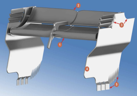
Figure 7. Components of Rare Wing [8]
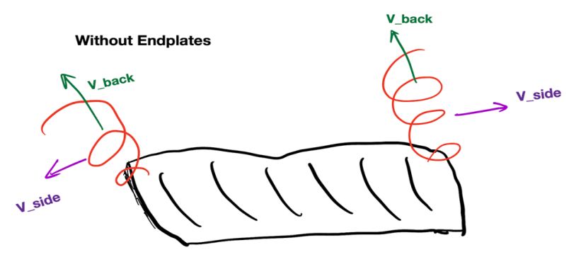
Figure 8. Airflow Model of Single Plane System.
3.3. Diffuser
Beneath the chassis, the ground clearance of F1 is about 75 millimeters [9]. Due to such a narrow clearance, the airflow beneath the underfloor is extremely fast. And according to Bernoulli’s effect, the underfloor area becomes an extremely low-pressure area as the car speeds up. Therefore, the high-pressure area on the top of the car pushes the car's body down with tons of downforce. The diffuser is located beneath the rare wing at the rare end of the car. It can be treated as the airflow exit under the car floor. The diffuser, shown in FIG 9, has multiple vertical strakes on it to guide the airflow to exit the underfloor with no separation of flow [9]. Guiding the airflow exit the underfloor is a crucial factor affecting the car's stability, especially when turning rapidly. Without this part, the airflow existing would generate strong turbulence in a relatively random direction and make the car less stable at a high-speed maneuver.
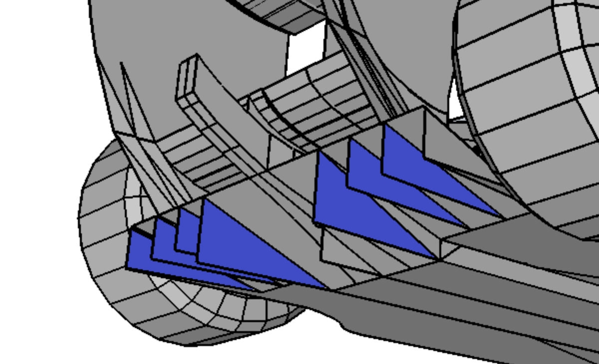
Figure 9. Structure of a Diffuser [9].
3.4. Bargeboard
The bargeboard is located between the front wheels and the side of the chassis, as shown in FIG 10. They are in smoothly curved shapes and placed on both sides of the car. They serve three main functions for an F1 car. First, a bargeboard smoothly directs the vortices generated by the front wing to keep the messy tire wakes away from the airflow. Secondly, it clears and directs the airflow to the engine’s air intake for cooling purposes. Lastly, it generates an airflow that “seals” the underfloor of the car, keeping the airflow beneath the underfloor from “escaping”.
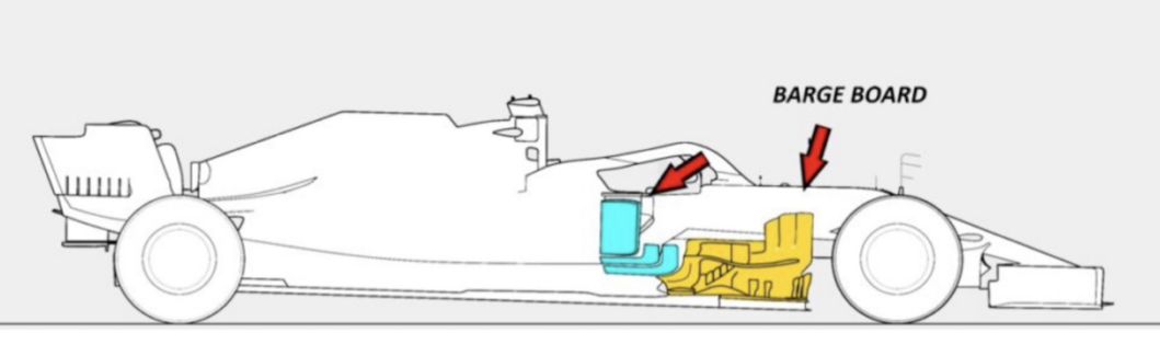
Figure 10. Barge Board Placement [10].
3.5. S-Duct
S-Duct is an S-shaped tunnel that's been built in the nose of an F1 car as shown in FIG 11. When airflow encounters the nose of the car, some portion flows to the top of the car, and the other flows to the underside of the car. For the upwash, the high-speed airflow and the nose's shape can cause airflow separation. And for the downwash, air pressure can build up in the lower nose area. Therefore, having an S-Duct opening from the bottom of the nose can release some of the built-up pressure and direct this pressured airflow into the S-shaped tunnel [11]. When the pressure airflow exits from the top, it helps with sucking the separate flow close to the boundary layer close to car's surface, and therefore, having more intact airflow.
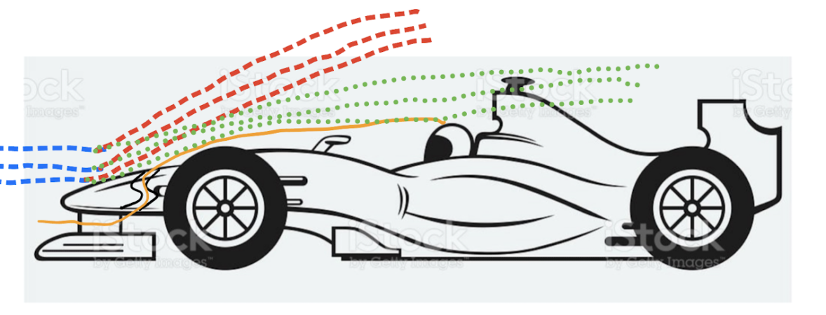
Figure 11. The S-Duct Diagram.
4. Conclusion
This study aims to understand the implementation of aerodynamic designs in FORMULA ONE racing cars. The research is conducted by analyzing the major aerodynamic-related parts in F1. This paper analyzed five main parts, including the front wing that provides downforce for the frontal axis and vortices generation; the rare wing that counterbalances the frontal downforce; the diffuser that guides the underfloor airflow exit smoothly; the bargeboards to shape the airflow closer to the car’s body; and the S-duct which releases the frontal pressure build-up. This study focuses more on the general physical characteristics, in aerodynamics, of F1 racing cars, rather than mathematical details. Hopefully, understanding how these aerodynamic components innovate motorsports can also inspire other related industries.
References
[1]. Duxbury, A., & Holding, J. (2022, May 30). How fast is an F1 car? top speeds of F1, IndyCar, motogp and more. Autosport. Retrieved September 27, 2022, from https://www.autosport.com/f1/news/how-fast-is-an-f1-car-top-speeds-of-f1-indycar-motogp-and-more-4980734/4980734/#:~:text=F1%20cars%20accelerate%20from%200,power%20from%20a%20standing%20start.
[2]. Scott, J. (n.d.). Ask US - airliner takeoff speeds. Aerospaceweb.org | Ask Us - Airliner Takeoff Speeds. Retrieved September 27, 2022, from http://www.aerospaceweb.org/question/performance/q0088.shtml
[3]. Sriram, P. S., Gopalarathnam, A., & Misenheimer, A. (2012). High-Downforce Airfoil Design for Motorsports. SAE International Journal of Materials and Manufacturing, 5(2), 478–489. http://www.jstor.org/stable/26268482
[4]. S.Bhuvaneswari, M.Abitha. International Journal of Emerging Technologies and Innovative Research, "Application of Bernoulli’s principle in airplane wings", (www.jetir.org | UGC and issn Approved), ISSN:2349-5162, Vol.5, Issue 8, page no. pp503-505, August-2018, Available at : http://www.jetir.org/papers/JETIRC006402.pdf
[5]. Ono, A. (2020, July 31). Slipstream and 'dirty air' explained. Racecar Engineering. Retrieved September 27, 2022, from https://www.racecar-engineering.com/tech-explained/slipstream-and-dirty-air-explained/
[6]. Fuller, M. J. (2003). Vortex. Vortex. Retrieved September 27, 2022, from https://www.formula1-dictionary.net/vortex.html
[7]. Giuliana, R. (2020, August 24). Tech 101: How does a Formula 1 front wing work? Motorsport Week. Retrieved September 27, 2022, from https://www.motorsportweek.com/2020/08/24/tech-101-how-does-a-formula-1-front-wing-work/
[8]. Media. (2022, March 6). How do formula 1 rear wings work?: F1 rear wing aerodynamics. F1 Chronicle. Retrieved September 27, 2022, from https://f1chronicle.com/how-do-formula-1-rear-wings-work-f1-technology/
[9]. Pretorius, L. (2021, December 14). How low is an F1 car? One Stop Racing. Retrieved September 27, 2022, from https://onestopracing.com/how-low-is-an-f1-car/#:~:text=What%20is%20this%3F,-Report%20Ad&text=The%20ground%20clearance%20of%20a,the%20cente-r%20of%20the%20car.
[10]. Giuliana, R. (2020, May 29). F1 tech: The rise of extreme bargeboard designs. Motorsport Week. Retrieved September 27, 2022, from https://www.motorsportweek.com/2020/05/29/f1-tech-the-rise-of-extreme-bargeboard-designs/
[11]. Warrier, R. (2021, July 24). F1 aerodynamics: S-duct. LTF1 Official. Retrieved September 27, 2022, from https://www.ltf1official.com/post/f1-aerodynamics-s-duct
Cite this article
Li,T. (2023). Aerodynamic designs in FORMULA ONE cars. Theoretical and Natural Science,18,91-97.
Data availability
The datasets used and/or analyzed during the current study will be available from the authors upon reasonable request.
Disclaimer/Publisher's Note
The statements, opinions and data contained in all publications are solely those of the individual author(s) and contributor(s) and not of EWA Publishing and/or the editor(s). EWA Publishing and/or the editor(s) disclaim responsibility for any injury to people or property resulting from any ideas, methods, instructions or products referred to in the content.
About volume
Volume title: Proceedings of the 2nd International Conference on Computing Innovation and Applied Physics
© 2024 by the author(s). Licensee EWA Publishing, Oxford, UK. This article is an open access article distributed under the terms and
conditions of the Creative Commons Attribution (CC BY) license. Authors who
publish this series agree to the following terms:
1. Authors retain copyright and grant the series right of first publication with the work simultaneously licensed under a Creative Commons
Attribution License that allows others to share the work with an acknowledgment of the work's authorship and initial publication in this
series.
2. Authors are able to enter into separate, additional contractual arrangements for the non-exclusive distribution of the series's published
version of the work (e.g., post it to an institutional repository or publish it in a book), with an acknowledgment of its initial
publication in this series.
3. Authors are permitted and encouraged to post their work online (e.g., in institutional repositories or on their website) prior to and
during the submission process, as it can lead to productive exchanges, as well as earlier and greater citation of published work (See
Open access policy for details).
References
[1]. Duxbury, A., & Holding, J. (2022, May 30). How fast is an F1 car? top speeds of F1, IndyCar, motogp and more. Autosport. Retrieved September 27, 2022, from https://www.autosport.com/f1/news/how-fast-is-an-f1-car-top-speeds-of-f1-indycar-motogp-and-more-4980734/4980734/#:~:text=F1%20cars%20accelerate%20from%200,power%20from%20a%20standing%20start.
[2]. Scott, J. (n.d.). Ask US - airliner takeoff speeds. Aerospaceweb.org | Ask Us - Airliner Takeoff Speeds. Retrieved September 27, 2022, from http://www.aerospaceweb.org/question/performance/q0088.shtml
[3]. Sriram, P. S., Gopalarathnam, A., & Misenheimer, A. (2012). High-Downforce Airfoil Design for Motorsports. SAE International Journal of Materials and Manufacturing, 5(2), 478–489. http://www.jstor.org/stable/26268482
[4]. S.Bhuvaneswari, M.Abitha. International Journal of Emerging Technologies and Innovative Research, "Application of Bernoulli’s principle in airplane wings", (www.jetir.org | UGC and issn Approved), ISSN:2349-5162, Vol.5, Issue 8, page no. pp503-505, August-2018, Available at : http://www.jetir.org/papers/JETIRC006402.pdf
[5]. Ono, A. (2020, July 31). Slipstream and 'dirty air' explained. Racecar Engineering. Retrieved September 27, 2022, from https://www.racecar-engineering.com/tech-explained/slipstream-and-dirty-air-explained/
[6]. Fuller, M. J. (2003). Vortex. Vortex. Retrieved September 27, 2022, from https://www.formula1-dictionary.net/vortex.html
[7]. Giuliana, R. (2020, August 24). Tech 101: How does a Formula 1 front wing work? Motorsport Week. Retrieved September 27, 2022, from https://www.motorsportweek.com/2020/08/24/tech-101-how-does-a-formula-1-front-wing-work/
[8]. Media. (2022, March 6). How do formula 1 rear wings work?: F1 rear wing aerodynamics. F1 Chronicle. Retrieved September 27, 2022, from https://f1chronicle.com/how-do-formula-1-rear-wings-work-f1-technology/
[9]. Pretorius, L. (2021, December 14). How low is an F1 car? One Stop Racing. Retrieved September 27, 2022, from https://onestopracing.com/how-low-is-an-f1-car/#:~:text=What%20is%20this%3F,-Report%20Ad&text=The%20ground%20clearance%20of%20a,the%20cente-r%20of%20the%20car.
[10]. Giuliana, R. (2020, May 29). F1 tech: The rise of extreme bargeboard designs. Motorsport Week. Retrieved September 27, 2022, from https://www.motorsportweek.com/2020/05/29/f1-tech-the-rise-of-extreme-bargeboard-designs/
[11]. Warrier, R. (2021, July 24). F1 aerodynamics: S-duct. LTF1 Official. Retrieved September 27, 2022, from https://www.ltf1official.com/post/f1-aerodynamics-s-duct