


1. Introduction
In various types of chips such as high-speed Digital Signal Processors, microprocessors, and Reduced Instruction Set Computers (RISC), multipliers are indispensable arithmetic logic units. Therefore, optimizing their speed and area is of paramount importance. The fundamental operational steps of a multiplier involve the generation and compression of partial products. Currently, the most widely applied multiplier algorithms and structures are the Radix_4 Booth algorithm and the Wallace tree structure [1]. This article delves into the Radix_4 Booth algorithm and the Wallace tree structure while simultaneously introducing a novel approach for designing a 32-bit signed multiplier. This approach involves the utilization of an improved version of the Radix_4 Booth algorithm, namely the approximate Booth algorithm, for generating partial products. Subsequently, the generated partial products are compressed using a Wallace tree structure featuring 4-2 compressors, deviating from the traditional 3-2 compressors. This reduction in compression stages to three minimizes the delay along the critical path, thereby enhancing overall performance. Furthermore, the compressed results from the Wallace tree are processed using an advanced carry lookahead adder, addressing the delay arising from mutual carry propagation in series-connected regular full adders. By adopting approximate Booth multiplier not only is the delay along the critical path reduced, but the layout area is also minimized.
2. Principle and structure
2.1. Principle of Radix_ 4 Booth Multiplier
The Radix_4 Booth algorithm’s theoretical justification is as follows: Assume that A is the n-bit multiplicand and B is the multiplier’s n-bit multiplier. A and B are the complement forms of ordinary binary. PP is the result of the multiplier. The operation of a multiplier can be expressed as:
PP=A×B (1)
The n-bit multiplier B can be expressed as: B= \( {b_{n-1}}{b_{2n-2}}...{b_{1}}{b_{0}} \) = \( {-b_{n-1}}{2^{n-1}}{b_{2n-2}}{2^{n-2}}...{b_{1}}{2^{1}}{b_{0}}{2^{0}} \) , Then:
B= \( {b_{n-1}}{b_{2n-2}}...{b_{1}}{b_{0}} \) = \( \sum _{i=0}^{\frac{n}{2}-1}(-2{b_{2i+1 }}+{b_{2i}}+{b_{2i+1 }}){×4^{i}} \) (2)
Bringing equation (2) into equation (1) yields:
PP=A×B= \( \sum _{i=0}^{n-1}A×(-2{b_{2i+1 }}+{b_{2i}}+{b_{2i+1 }})×{4^{i}} \) (3)
Specifically, when i=0, b-1 with the value of 0, it is necessary to add a “0” bit after the least significant bit of multiplier B during Booth algorithm encoding [2]. After filling in “0”, to obtain the corresponding partial product, encode the multiplicand by crossing three adjacent bits of the multiplier. All cases of \( {b_{2i+1 }}{b_{2i }}{b_{2i-1 }} \) are listed in the table, where \( {PP_{i }} \) is the partial product generated by encoding and Neg is the symbol compensation bit. The Radix_4 Booth algorithm encoding mode is shown in table 1.
Table 1. Radix_4 Booth algorithm encoding mode.
\( {b_{2i+1 }}{b_{2i }}{b_{2i-1 }} \) | \( {PP_{i }} \) | Neg |
000 | +0 | 0 |
001 | +A | 0 |
010 | +A | 0 |
011 | +2A | 0 |
100 | -2A | 1 |
101 | -A | 1 |
110 | -A | 1 |
111 | -0 | 1 |
When \( {b_{2i+1 }}{b_{2i }}{b_{2i-1 }} \) are 000 and 111, the value of the partial product \( {PP_{i }} \) obtained is +0, so all partial products in this row are 0. When \( {b_{2i+1 }}{b_{2i }}{b_{2i-1 }} \) are 001 and 010, the value of the partial product PPi obtained is 0 [3]. When \( {b_{2i+1 }}{b_{2i }}{b_{2i-1 }} \) are 011, the resulting partial product \( {PP_{i }} \) has a value of +2A, achieved by shifting the multiplier one bit to the left. When the three adjacent bits of the multiplier \( {b_{2i+1 }}{b_{2i }}{b_{2i-1 }} \) are 100, the value of the partial product \( {PP_{i }} \) obtained is -2A. Firstly, shift the multiplier A to the left one bit to obtain +2A, and then use an inverter to negate +2A, with the sign compensation bit Neg being 1 [4]. When \( {b_{2i+1 }}{b_{2i }}{b_{2i-1 }} \) are 101 and 110, the value of the partial product \( {PP_{i }} \) obtained is -A. \( {PP_{i }} \) is achieved by inverting the multiplicand A through an inverter and adding the sign compensation bit Neg to its least significant bit [5].
2.2. Principle of Wallace Tree
A parallel structure called a Wallace Tree is frequently used to create high-speed multipliers. The design concept of Wallace Tree is to split multiplication operations into different parts and improve the speed of operations through parallel computing [6]. It uses a hierarchical structure, where partial multiplication and accumulation are performed on each layer, resulting in the complete product.
The following is the working principle of the 64-bit multiplier Wallace Tree: In the booth algorithm, two 32-bit multipliers are divided into multiple partial products. The product of each part is usually 3 bits. The multiplier and the multiplicand are multiplied bit by bit, resulting in a partial product and corresponding carry.
For each 3-bit partial product, perform a series of bit alignment and partial sum operations. These operations add the products of adjacent parts and maintain the correctness of carry. Firstly, perform a bit alignment operation. Shift the products of adjacent parts left and right based on their weights to align them. For multi-level Wallace trees, multiple rounds of bit alignment operations are required. Then, proceed with the partial sum operation. Add the products of adjacent aligned parts and consider the carry from the previous level. This can be achieved through a full adder circuit to ensure the correct sum and carry. After multiple rounds of bit alignment and partial sum operations, the obtained partial sum can continue to the next round of bit alignment and partial sum operations until the final 64-bit multiplication result is obtained [7]. The structure of 4-2 Wallace compression tree is shown in figure 1.
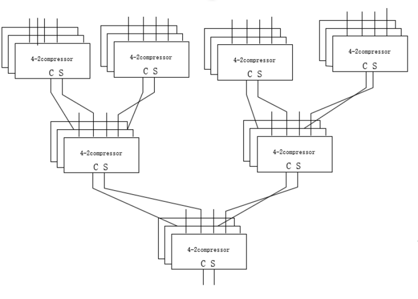
Figure 1. Structure of 4-2 Wallace compression tree (Photo/Picture credit: Original).
In this essay, the utilization of 4-2 compressors stems from their effectiveness in managing addition and subtraction operations involving extensive numerical data. When dealing with multiple sets of data, it is customary to compress these operands. This compression process is executed through a Wallace tree, which comprises an arrangement of compressors. Presented below is a gate level and logical expressions overview of the 4-2 compressor. When given four inputs and a (carry-in), the 4-2 compressor produces both Sum and Carry outputs as well as one that can be used in the subsequent 4-2 compressor’s. The 4-2 compressor gate level circuit is shown in figure 2.
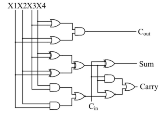
Figure 2. 4-2 compressor gate level circuit (Photo/Picture credit: Original).
The 4-2 compressor logical expressions as showed as followed:
\( Cout = X3 ⋁ X4 ⋀ X1 ⋁ X2 \) (4)
\( Sum = X3⊕X4⊕X1⊕X2⊕Cin \) (5)
\( Carry = X1 ⋀ ( \overline{X4 ⊕ X3 ⊕ X2 ⊕X1}) ⋁ Cin ⋀ ( \overline{X4 ⊕ X3 ⊕ X2 ⊕X1}) \) (6)
2.3. Principle of Carry Ahead Adder
A parallel adder called the Carry Ahead Adder was created to enhance the regular full adder by primarily addressing the mutual carry delay that occurs when a regular full adder is coupled in series. If the ith bit of a binary adder is \( {A_{i }} \) and \( {B_{i }} \) , the carry input is \( {C_{i }} \) ,the output is \( {S_{i }} \) , and the carry output is \( {C_{i+1 }} \) , then:
\( {S_{i }}={A_{i }}⊕{B_{i }}⊕{C_{i }} \) (7)
\( {C_{i+1 }}= {(A_{i }}⋀ {B_{i }}) ⋁ ({A_{i }}⋀ {C_{i }}) ⋁ ({A_{i }}⋀ {B_{i }})={(A_{i }}⋀ {B_{i }}) ⋁ {(A_{i }}⋁ {B_{i }}) ⋀ {C_{i }} \) (8)
If \( {G_{i }}={A_{i }}⋀ {B_{i }} \) , \( {P_{i }}={A_{i }}⋁ {B_{i }} \) , then \( {C_{i+1 }}={G_{i }}⋁ {P_{i }}⋀ {C_{i }}. \) When \( {A_{i }} \) and \( {B_{i }} \) are both 1, \( {G_{i }}= 1 \) , resulting in \( {C_{i+1 }}=1 \) ; When \( {A_{i }} \) and \( {B_{i }} \) exist with a value of 1, \( {P_{i }}= 1 \) , pass \( {C_{i+1 }}={ C_{i+1 }} \) . Therefore, \( {G_{i }} \) generates a signal for carrying, while \( {P_{i }} \) carries the signal. \( {G_{i }} \) has a higher priority than pi, which means that when \( {G_{i }}= 1 \) and \( {P_{i }}= 1 \) , a carry is unconditionally generated regardless of \( {C_{i }} \) .The carry output is \( {C_{i }} \) related to the logic before \( {C_{i }} \) when \( {G_{i }}=0 \) and \( { P_{i }}= 1 \) . A circuit that performs the logical expression above is a Carry Look ahead Unit, or a CLA component for short. The adder that uses this carry method is a carry ahead adder. It is a kind of parallel carry adder, since each carry is produced in parallel. More digits on a CLA component simply increase the number of inputs to the logic gate, not the number of logic gate levels. However, the number of connections and entries in the CLA component will greatly increase the delay of the gate and will not improve circuit performance. Hence, adders with more bits can be built with 4-bit CLA components and 4-bit carry-ahead adders.
3. Implementation and simulation
The multiplier in this study is described using Verilog HDL and functionally simulated using Vivado software. By writing testbench files with six sets of random 32-bit signed inputs, test data for 64-bit signed numbers is computed. The calculations reveal that the results are accurate.
3.1. Radix_4 booth RTL schematic and simulation result
The methodology employed in this study involves encoding a 32-bit signed multiplier using the Radix-4 Booth algorithm, and then corresponding bit operations are performed on the 32-bit signed multiplicand, resulting in the generation of sixteen 64-bit signed partial products. The generated partial product is arranged in an array form for the convenience of compressing the tree structure [8]. The approach to handling the symbol compensation bit involves logical gate operations, and logical expressions are derived through Karnaugh map simplification. In the Vivado software, utilizing Verilog HDL’s case statement to generate 64-bit signed partial products, a logical expression for the symbol compensation bit (Neg) is formulated as follows:
\( Neg = {b_{2i+1 }}⋀ \overline{{b_{2i }}}⋁{ b_{2i+1 }} ⋀ \overline{{ b_{2i-1 }}} \) (9)
Subsequently, the outcome of the sign extension bit is integrated into the Wallace tree, where parallel computations are executed alongside the 64-bit signed partial products within the 4-2 compressor. This strategy effectively enhances the operational efficiency of the multiplier within a single clock cycle [6]. Vivado was used to implement the code for the Radix-4 Booth method used in this work and its simulation. This implementation includes equivalent conditional statements and logical gate expressions for scenarios using sign extension bits (Neg). The Radix_4 booth RTL schematic is shown in figure 3.
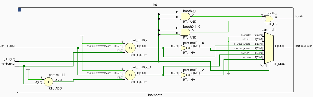
Figure 3. Radix_4 booth RTL schematic (Photo/Picture credit: Original).
The simulation result of the Radix_4 booth is shown in figure 4.
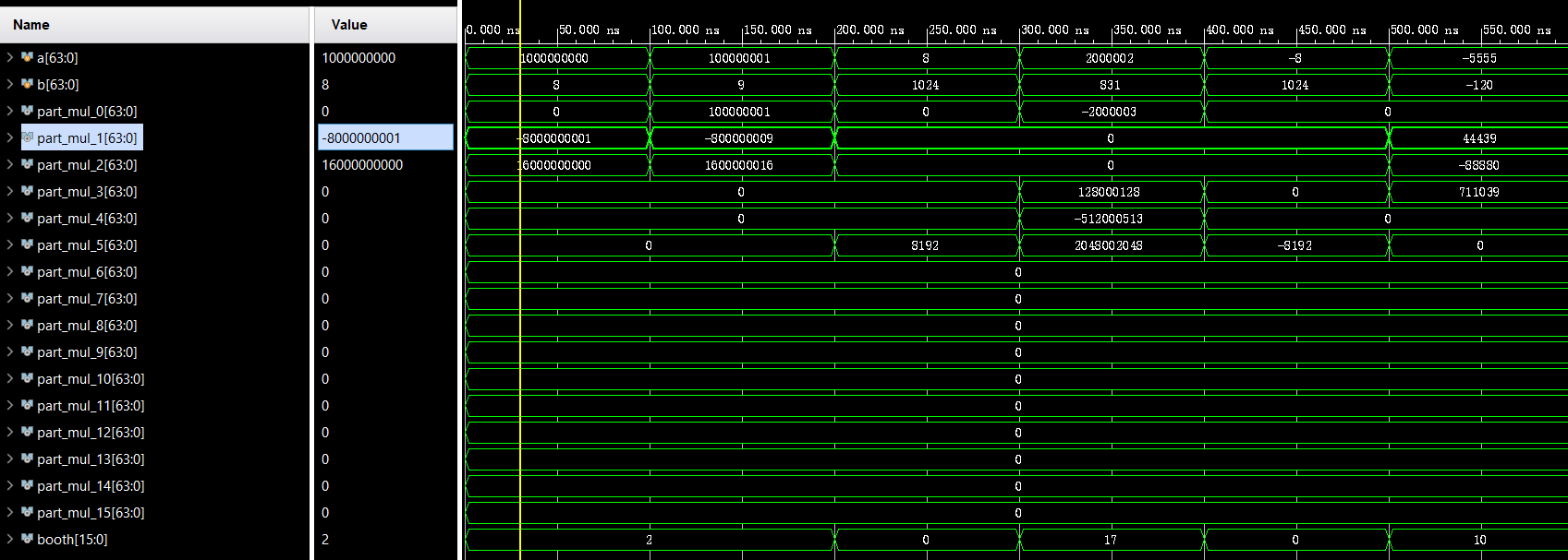
Figure 4. The simulation result of the Radix_4 booth (Photo/Picture credit: Original).
3.2. Wallace tree multiplier utilizing 4-2 compressor
In this study, the 64-bit signed partial products are compressed using 4-2 compressors using the Wallace tree. According to Figure 1, the Wallace tree consists of three layers. The first layer includes com00, com01, com02, and com03, where the 4-2 compressors take their four inputs from the 64-bit signed partial products, and the fifth input is the symbol compensation bit generated from the Radix_4 Booth algorithm.
However, in the second and final layers of the Wallace tree, the 4-2 compressors’ four inputs comprise not only the Sum values from the previous level’s 4-2 compressors but also a combination of Carry and symbol compensation bit. Since the Carry is left-shifted by one bit compared to the Sum, the Carry only considers bits 0 to 62, and the remaining one bit is filled by one symbol compensation bit. The Wallace tree RTL schematic is shown in figure 5.
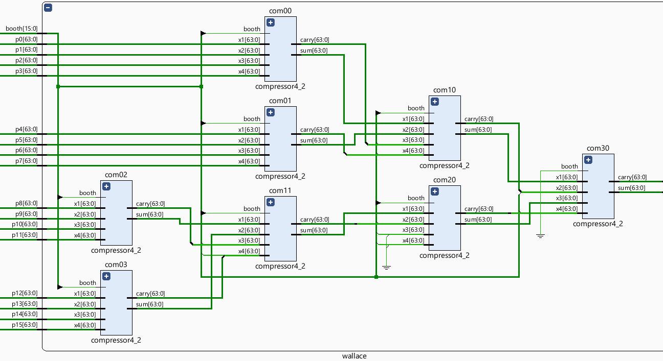
Figure 5. Wallace tree RTL schematic (Photo/Picture credit: Original).
The circuit gate expression of the 4-2 compressor is displayed by the Vivado program. The 4-2 compressor logic gate flow is shown in figure 6.
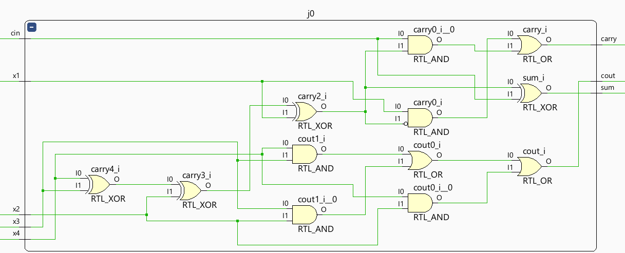
Figure 6. The 4-2 compressor logic gate flow (Photo/Picture credit: Original).
The summation outcome of both Wallace_c and Wallace_s corresponds to the ultimate product of the two 32-bit signed numbers. The simulation result of the Wallace tree with 4-2 compressors is shown in figure 7.
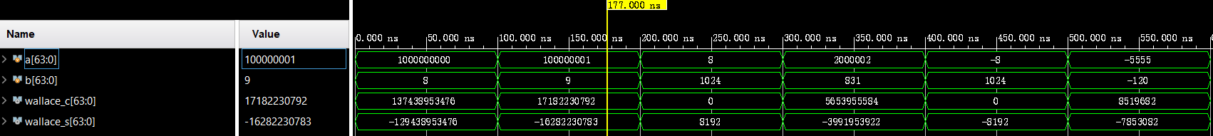
Figure 7. The simulation result of the Wallace tree with 4-2 compressors.
(Photo/Picture credit: Original)
3.3. 64-bit carry ahead adder
A 64-bit advance carry adder is a digital circuit used to perform the addition operation of 64-bit binary numbers. Compared with the traditional continuous carry adder, the advance carry adder can pre-calculate the carry of each bit in parallel during the addition process, which significantly reduces the delay of carry propagation and thus increases the speed of the addition operation [9].
Input: The input is two 64-bit binary numbers, usually labelled A and B. These numbers are represented using their respective 64-bit binary arrays. Output: The output of the 64-bit advance carry adder is a 65-bit binary number. The first 64 bits represent the sum of the input numbers in each bit, and the 65th bit is the carry output of the most significant bit (MSB).
The advanced carry adder is useful because it can predict the carry before the addition operation. This prediction allows the carry to propagate in parallel during addition, greatly reducing the overall latency. The model of 64-bit carry-ahead adder is shown in figure 8.
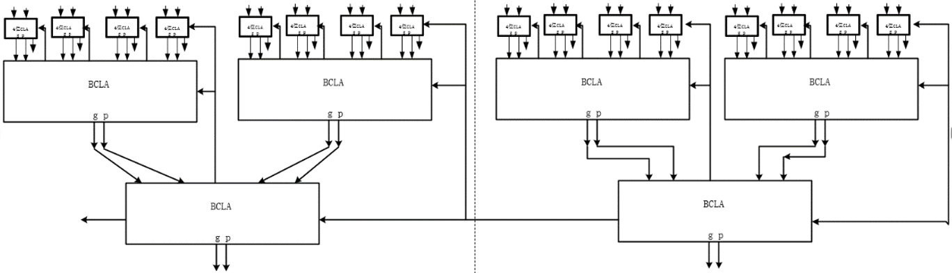 Figure 8. The model of 64-bit carry-ahead adder (Photo/Picture credit: Original).
The principle of the adder can be roughly divided into four steps: (1) Recalculating the carry of each bit. This step involves getting the carry output of each bit from the input bit in each pair, the carry of the previous bit, and the carry generator of the previous bit. (2) At each bit, it adds the corresponding bits from A and B to the pre-calculated carry. (3) Calculate the sum of the bit and the carry output. This step is done in parallel and does not propagate the carry bit by bit like a continuous carry adder. (4) Repeat this process until all 64 bits have been processed. The implementation of the advance carry adder requires the use of a logic gate circuit and a pre-calculated carry generator. The RTL schematic is shown in figure 9.
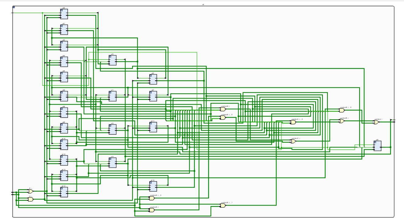
Figure 9. RTL schematic (Photo/Picture credit: Original).
Simulation results: The two-input data are 64-bit symbol numbers, the input carry is 0, the output is a 64-bit symbol number, and the 65th bit is regarded as overflow data. The Simulation results is shown in figure 10.
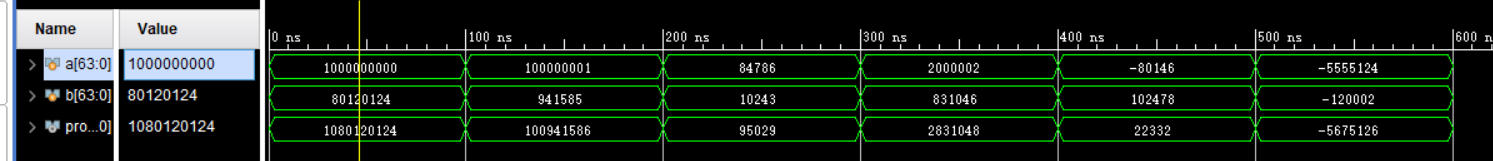
Figure 10. Simulation results (Photo/Picture credit: Original).
4. Construction and Analysis of Approximate Multipliers
The accurate Booth multiplier is an algorithm used for binary multiplication, which achieves multiplication by generating and accumulating partial products. However, it can be complex, especially in hardware implementations. The approximate Booth multiplier is a method that sacrifices some precision to reduce computation cost or latency. It is primarily used in applications where lower computational accuracy is acceptable, but higher computational efficiency and resource utilization are required. Examples include embedded systems, audio and image processing, machine learning inference, cryptographic applications, image and audio codecs [10].
The ensuing enumeration delineates several methodological paradigms germane to the practice of approximative Booth multiplication: a. Partial Precision Booth Multiplier: In multiplication operations, you can reduce the precision of partial products to decrease the computation load. This means that during multiplication, some bits can be discarded, thereby reducing the computation requirements. This method can provide sufficient accuracy in certain applications while lowering computational complexity. b. Approximate Encoding Booth Multiplier: This method encodes the multiplicand to reduce partial sum and shift operations in the multiplier. This approach often introduces some approximation to reduce hardware resource usage. c. Table-based Approximate Booth Multiplier: Approximate Booth multiplication can be performed using a table-based approach, especially for common multiplicand values. By precomputing partial products and storing them in a lookup table, computation can be reduced. However, this may introduce some error. d. Probabilistic Booth Multiplier: This method uses a probabilistic approach to perform multiplication by introducing randomness, which can reduce computational complexity in some cases. This usually involves random number generation and probabilistic algorithms.
It’s important to note that the application of approximate Booth multipliers requires careful consideration based on specific needs and use cases. Reducing precision or introducing approximation can impact the correctness and precision of computations. Therefore, when selecting an approximate Booth multiplier, careful consideration is necessary.
The research paper unveils an innovative approximation technique for the Booth encoder and a corresponding structure involving a reduction tree. In this method, the approximated Booth encoder intentionally introduces positive discrepancies during the generation of partial products. Simultaneously, the structure of the approximated reduction tree is tailored to diminish partial products, thereby introducing negative deviations. This orchestrated interplay aims to effectively balance out errors and achieve compensation for inaccuracies.
The novel approximation strategy for the Booth encoder revolves around a creative approach: reversing the numeric values within the Karnaugh map of the Radix_4 Booth encoder. In this context, the notation “1→0” signifies the transformation of an output value from 1 to 0, while conversely, “0→1” denotes a shift from an output value of 0 to 1. The specifics of this new Booth encoder design leverage this mechanism.
The Karnaugh map portraying the approximation process of the multiplier is visually represented in Table 2.
Table 2. Karnaugh map of the approximate multiplier.
\( { b_{2i+1}}{b_{2i}}{b_{2i-1}} \) \( {a_{j}}{a_{j-1}} \) | 000 | 001 | 011 | 010 | 110 | 111 | 101 | 100 |
00 | 0 | 0 | 0 | 0 | 1 | 0→1 | 1 | 1 |
01 | 0 | 0 | 1→0 | 0 | 1 | 0→1 | 1 | 0→1 |
11 | 0 | 1 | 1 | 1 | 0 | 0 | 0 | 0 |
10 | 0 | 1 | 0→1 | 1 | 0 | 0 | 0 | 1→0 |
Among these alterations, there are 4 instances where approximate values shift from 0 to 1, and 2 instances where approximate values shift from 1 to 0. Consequently, in the initial iteration of the new approximate Booth encoder introduced in this study, there is a prevalence of positive errors compared to accurate values, resulting in a net positive deviation in errors. The error rate of this novel approximation method for the Booth encoder is calculated as follows: P1 = 6/32 = 18.75%. This signifies that approximately 18.75% of the cases exhibit errors under this approach.
As discerned from table 2, the logical expression of the proposed approximative Booth encoder is elucidated as presented in equation (10).
\( {APP_{ij}}={a_{j }}⋀ \bar{{b_{2i+1}}} {⋀ b_{2i-1}} ⋁ {a_{j}} ⋀ \bar{{b_{2i+1}}} {⋀ b_{2i}} ⋁ \bar{{a_{j}}} ⋀{ b_{2i+1}} \) (10)
The Gate-level circuit of the approximate encoder is shown in figure 11.
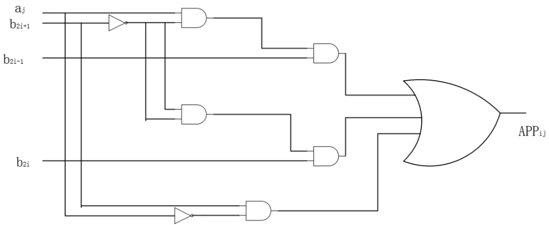
Figure 11. Gate-level circuit of the approximate encoder (Photo/Picture credit: Original).
In this context, \( {APP_{ij}} \) designates the partial product generated by the proposed approximative Booth encoder for the i-th row and j-th column. The range of values for i spans from 0 to 15, while the range for j extends from 0 to 31. “ \( {a_{j}} \) ” signifies a bit from the multiplicand, and “b[2i-1]”, “b[2i]”, and “b[2i+1]” correspond to the adjacent three bits of the multiplier.
During the multiplication operation involving a 32-bit signed number, where the 32nd bit represents the sign bit, applying Karnaugh map inversion can lead to significant discrepancies in the outcome. Consequently, when calculating the final bit, as indicated in table 2, precise Booth encoding is performed. The logical expression for this scenario is depicted in equation (11).
\( {APP_{ij}}=({b_{2i}}{⊕b_{2i-1}}) ⋀ ({b_{2i+1}}⊕{a_{j}}) ⋁ (\bar{{b_{2i}}⊕{b_{2i-1}}}) ⋀ ({b_{2i}}⊕{b_{2i+1}}) ⋀ ({b_{2i+1}}⊕{a_{j-1}}) \) (11)
The Gate-level circuit of the accurate encoder is shown in figure 12.
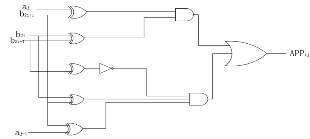
Figure 12. Gate-level circuit of the accurate encoder (Photo/Picture credit: Original).
Upon analyzing the two designs, it is evident that the gate-level arrangement of the Radix_4 Booth encoder includes a total of 1 OR gate, 1 inverter, 2 AND gates, 3 NOR gates, and 5 XOR gates. In sharp contrast, the gate-level configuration of the approximate Booth encoder is constructed using only 2 inverters, 5 AND gates, and 1 OR gate. This juxtaposition underscores a noticeable disparity in logic gate quantities between these two designs, with the approximate encoder employing notably fewer logic gates compared to the Radix_4 Booth encoder.
5. Conclusion
In this article, the Radix_4 Booth algorithm is implemented to encode the 32-bit signed multiplier, and subsequently, the article employs a Wallace tree structure. Using 4-2 compressors, it compresses the 64-bit signed partial products, resulting in a 32-bit multiplier. Additionally, the use of an advanced carry lookahead adder significantly enhances the operational speed of the multiplier. The design also introduces an approximate Booth multiplier, which, when compared with the 32-bit multiplier using the Radix-4 Booth algorithm, exhibits lower power consumption and a shorter critical path.
Big data, cloud computing, and the Internet of Things are three emerging technologies that are posing significant hardware and power supply concerns for terminal devices. The demand for novel, effective, and low-power computer systems is on the rise. However, it should be noted that the multiplier proposed in this design is a 32-bit signed multiplier, constrained by its bit width. Therefore, further research will be conducted in subsequent work to address considerations related to bit width. The experimental comparisons conducted in this study are relatively limited, resulting in incomplete experimental data. Future research endeavours will focus on refining experimental comparisons to scientifically identify the optimal design solution.
Authors Contribution
All the authors contributed equally and their names were listed in alphabetical order.
References
[1]. Wu MQ, Zhao HL and Liu XH 2019 A design of multiplier based on modified Booth⁃4 algorithm and Wallace tree (Electronic Design Engineering) p145-150
[2]. Sheng YX 2022 Design of Approximate Booth Multiplier Based on Error Compensation (Hefei University of Technology)
[3]. Zhai ZY and Han ZG 2014 32 Bit Pipeline Multiplier Design Based on Booth Encoder(Microelectronics & Compute)p146-149
[4]. Wang JL and Hu YL 2020 Design and implementation multiplier based on new booth selector and compressor ( Microelectronics & Compute) p5-8
[5]. Huang T, Run R and Hu Y 2023 Design of a high energy efficiency based 4-Booth coding parallel multiplier (Application of Electronic Technique)p117-122
[6]. Wang D, Yu NM and Zhang YL 2007 Low Power and High-Speed Parallel Multiplier Design Using Modified Booth Wallace Tree (Chinese Journal of Electron Devices) p252-255
[7]. Shao L, Zhang SD and Yu ZG 2007 The Design of Wallace Tree by Using a Structure of Modified Mixed Compression (electronics & packaging )p12-14+18
[8]. Shi M,Wang G,Yi QM 2016 An Optimised Design Of Multiplier Based On Improved Booth Encoding And Wallace Tree (Computer Applications and Software) P13-16
[9]. Xuan-Vy Luu, Trong-Thuc Hoang, and Trong-Tu Bui 2014 A High-speed Unsigned 32-bit Multiplier Based on Booth-encoder and Wallace-tree Modififications (International Conference on Advanced Technologies for Communications)
[10]. Sheng YX, Zhang SD and Yu ZG 2022 An Approximate Booth Multiplier Based on Novel Wallace Tree(Microelectronics)
Cite this article
Liu,C.;Sun,J.;Tang,R. (2024). A design of multiplier based on Radix_4 Booth algorithm and 4-2 Wallace compression tree. Applied and Computational Engineering,37,166-176.
Data availability
The datasets used and/or analyzed during the current study will be available from the authors upon reasonable request.
Disclaimer/Publisher's Note
The statements, opinions and data contained in all publications are solely those of the individual author(s) and contributor(s) and not of EWA Publishing and/or the editor(s). EWA Publishing and/or the editor(s) disclaim responsibility for any injury to people or property resulting from any ideas, methods, instructions or products referred to in the content.
About volume
Volume title: Proceedings of the 2023 International Conference on Machine Learning and Automation
© 2024 by the author(s). Licensee EWA Publishing, Oxford, UK. This article is an open access article distributed under the terms and
conditions of the Creative Commons Attribution (CC BY) license. Authors who
publish this series agree to the following terms:
1. Authors retain copyright and grant the series right of first publication with the work simultaneously licensed under a Creative Commons
Attribution License that allows others to share the work with an acknowledgment of the work's authorship and initial publication in this
series.
2. Authors are able to enter into separate, additional contractual arrangements for the non-exclusive distribution of the series's published
version of the work (e.g., post it to an institutional repository or publish it in a book), with an acknowledgment of its initial
publication in this series.
3. Authors are permitted and encouraged to post their work online (e.g., in institutional repositories or on their website) prior to and
during the submission process, as it can lead to productive exchanges, as well as earlier and greater citation of published work (See
Open access policy for details).
References
[1]. Wu MQ, Zhao HL and Liu XH 2019 A design of multiplier based on modified Booth⁃4 algorithm and Wallace tree (Electronic Design Engineering) p145-150
[2]. Sheng YX 2022 Design of Approximate Booth Multiplier Based on Error Compensation (Hefei University of Technology)
[3]. Zhai ZY and Han ZG 2014 32 Bit Pipeline Multiplier Design Based on Booth Encoder(Microelectronics & Compute)p146-149
[4]. Wang JL and Hu YL 2020 Design and implementation multiplier based on new booth selector and compressor ( Microelectronics & Compute) p5-8
[5]. Huang T, Run R and Hu Y 2023 Design of a high energy efficiency based 4-Booth coding parallel multiplier (Application of Electronic Technique)p117-122
[6]. Wang D, Yu NM and Zhang YL 2007 Low Power and High-Speed Parallel Multiplier Design Using Modified Booth Wallace Tree (Chinese Journal of Electron Devices) p252-255
[7]. Shao L, Zhang SD and Yu ZG 2007 The Design of Wallace Tree by Using a Structure of Modified Mixed Compression (electronics & packaging )p12-14+18
[8]. Shi M,Wang G,Yi QM 2016 An Optimised Design Of Multiplier Based On Improved Booth Encoding And Wallace Tree (Computer Applications and Software) P13-16
[9]. Xuan-Vy Luu, Trong-Thuc Hoang, and Trong-Tu Bui 2014 A High-speed Unsigned 32-bit Multiplier Based on Booth-encoder and Wallace-tree Modififications (International Conference on Advanced Technologies for Communications)
[10]. Sheng YX, Zhang SD and Yu ZG 2022 An Approximate Booth Multiplier Based on Novel Wallace Tree(Microelectronics)